1
RF Generator
User Manual
SAG_UM_04-00_EN
RF Generator User Manual
Table of Contents
PrefaceIV
1
Functional Principles
1
1.1Functional Principles of RF Ablation.................................................................................................... 1
1.2
Power Controlled Ablation Method..................................................................................................... 2
1.3
Temperature Controlled Ablation Method........................................................................................ 2
1.4
Unipolar Application Method................................................................................................................ 3
1.5
Measuring Impedance.............................................................................................................................. 3
2Indications
5
3
6
4
Warnings and Precautions
3.1
Warnings: Generator Usage.................................................................................................................... 6
3.2
Warnings: System Safety and Connections....................................................................................... 9
3.3
Warnings and Precautions: During an Ablation Procedure.......................................................10
3.4
Handling Indifferent Electrodes..........................................................................................................11
System Overview and Setup
4.1
14
Structure and Features...........................................................................................................................14
4.2Controls on the Front of the Generator............................................................................................15
4.3Controls on the Back of the Generator.............................................................................................16
4.4Functional Test and On-Site Training.................................................................................................17
4.5Setup.............................................................................................................................................................17
4.5.1 Setting Up the Generator.......................................................................................................17
4.5.2 Mains Connection.....................................................................................................................17
4.5.3Fuses..............................................................................................................................................17
4.5.4 Potential Equalization.............................................................................................................18
4.5.5Circular Plug Connections.....................................................................................................18
4.5.6Connection Cables and Catheters......................................................................................18
4.5.7 Indifferent Electrode Connections.....................................................................................18
4.5.8Ethernet Connection...............................................................................................................19
4.5.9 USB Connection........................................................................................................................19
4.5.10 Serial Data Connections.........................................................................................................19
4.5.11Fiber Optic Connections.........................................................................................................19
4.5.12 Setting Up Irrigated Catheters with the Irrigation Pump and Tubing...................19
4.5.13 Tilting the Generator’s Front Panel (Generators with a Tilt Panel button)...........19
4.5.14 Tilting the Generator’s Front Panel (Generators without a Tilt Panel button).....20
4.6Cleaning and Disinfecting the Generator........................................................................................20
4.7
Protecting Against Damage..................................................................................................................20
4.8Disposal........................................................................................................................................................21
i
RF Generator User Manual
5Accessories
5.1
22
Diagram of the Generator and Accessories.....................................................................................22
5.2Accessory Lists...........................................................................................................................................23
5.2.1Devices.........................................................................................................................................23
5.2.2Foot Pedal....................................................................................................................................24
5.2.3 SmartAblate™ Cables...............................................................................................................24
5.2.4 Indifferent Electrodes and Cables available from STOCKERT GmbH.....................26
5.2.5Catheters......................................................................................................................................26
5.3Caring for Accessories.............................................................................................................................27
5.3.1Connection Cables...................................................................................................................27
5.3.2 Indifferent Electrodes..............................................................................................................27
5.3.3Foot Pedal....................................................................................................................................27
5.4Cleaning, Disinfecting, and Sterilizing Accessories......................................................................27
6
Generator Operation
6.1
28
Quick Overview.........................................................................................................................................28
6.1.1 System Startup...........................................................................................................................28
6.1.2 System Shutdown.....................................................................................................................29
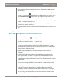
6.1.3Screens..........................................................................................................................................29
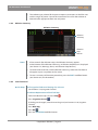
6.1.4 Screen Features.........................................................................................................................31
6.1.5 Data Entry Knob........................................................................................................................32
6.1.6Foot Pedal....................................................................................................................................32
6.1.7 Typical Procedure Process – Quick.....................................................................................33
6.1.8 Typical Procedure Process – Full..........................................................................................33
6.2Connections...............................................................................................................................................34
6.3Presets...........................................................................................................................................................39
6.3.1 Preset Overview........................................................................................................................39
6.3.2 Selecting a Preset......................................................................................................................39
6.3.3Editing a Preset..........................................................................................................................40
6.3.4Editing a Preset – Temporary Save......................................................................................44
6.3.5Creating a New Preset.............................................................................................................45
6.3.6 Designating a Default Preset................................................................................................46
6.3.7 Deleting a Preset.......................................................................................................................46
6.3.8 Displaying One Physician’s Presets.....................................................................................46
6.3.9Adding a Name to the Physician Presets List..................................................................47
6.3.10 Irrigation Control......................................................................................................................47
6.3.11Changing Audio Settings.......................................................................................................49
6.3.12 Selecting Ablation Display Settings...................................................................................49
6.3.13Copying Presets to a USB Flash Drive................................................................................50
6.4Ablation........................................................................................................................................................51
6.4.1 Starting a New Procedure......................................................................................................52
6.4.2 Starting and Stopping Ablation..........................................................................................52
6.4.3 Making Temporary Changes to Ablation Settings........................................................53
6.4.4Ablation Summary...................................................................................................................54
6.4.5 Low Fluid Level..........................................................................................................................54
ii
RF Generator User Manual
6.5
Post Procedure...........................................................................................................................................56
6.5.1Exporting Ablation and Event Log Data to a USB Flash Drive..................................56
6.6Flushing to Eliminate Air in the Tubing and Catheter.................................................................58
6.7
System Control..........................................................................................................................................59
6.7.1 Making the Generator the System Master.......................................................................59
6.8
Volume, Brightness, and Foot Pedal Test.........................................................................................60
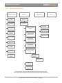
6.9Flowchart of the Screens.......................................................................................................................61
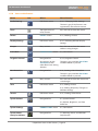
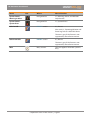
6.10 Icons on the Screens................................................................................................................................62
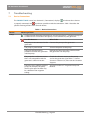
7Troubleshooting
64
7.1
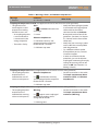
Device Connections.................................................................................................................................64
7.2
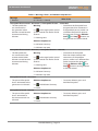
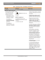
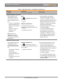
Warnings, Alerts, and Ablation Stop Reasons................................................................................67
7.3
System Errors..............................................................................................................................................83
7.3.1 System Error................................................................................................................................83
7.3.2Fatal System Error.....................................................................................................................83
7.4
Other Troubleshooting...........................................................................................................................84
7.5Calibrating the Touch Screen...............................................................................................................84
8
Technical Data
85
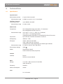
8.1Specifications.............................................................................................................................................85
8.2
Storage and Shipping Conditions......................................................................................................86
8.3
Operating Conditions.............................................................................................................................86
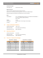
8.4ThermoCool® Catheter Preset Ranges...............................................................................................86
8.5Alarm and Touch Specifications..........................................................................................................87
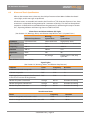
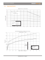
8.6
Output Specifications.............................................................................................................................88
8.7
Safety Inspections....................................................................................................................................89
8.8Maintenance...............................................................................................................................................90
8.9Repairs..........................................................................................................................................................90
8.10Conformance to Standards...................................................................................................................91
8.11EMC Information and Technical Description..................................................................................92
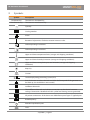
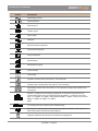
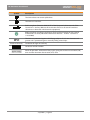
9Symbols
97
10Warranty
100
10.1 Transit Damage.......................................................................................................................................100
10.2Warranty.....................................................................................................................................................100
10.3 Product Liability......................................................................................................................................100
11References
101
iii
RF Generator User Manual
Preface
The SmartAblate™ Radiofrequency (RF) Generator is a highly specialized device intended for use
during RF ablation therapy of the human heart. This device is used in conjunction with specialized
therapeutic catheters and a dispersive pad (indifferent electrode) to create a closed electrical circuit
capable of delivering specified doses of RF energy. The RF energy is delivered to cardiac tissue that
forms unwanted electrical pathways that either drive or maintain arrhythmias. The RF energy heats
the tissue such that it becomes denatured and no longer functional. This interrupts and/or destroys
the unwanted electrical pathways, thereby restoring normal heart function.
The SmartAblate™ RF Generator actively generates specified doses of RF energy and continuously
monitors, displays, and coordinates the amount of RF energy, the temperature of the catheter’s
ablation electrode, and the tissue impedance during ablation therapy. The temperature of the
catheter’s ablation electrode is measured by a sensor in the electrode and is transmitted to the
generator. Simultaneously, high resolution impedance measurement circuits built into the generator
measure the heart tissue impedance allowing detection of small tissue changes prior to, during,
and after treatment. Before and during treatment, electrical signals generated by the heart are
also detected and transmitted by the catheter through the generator to connected monitoring
instruments. These signals in combination with the temperature of the ablation electrode, tissue
impedance, and RF energy information are used by the operator to control the safe delivery of RF
energy to locations within the heart that require treatment.
The SmartAblate™ RF Generator was designed to ensure simple, intuitive, and user-friendly operation.
This device features a touch screen for making selections and setting parameters. Among the
features of the screen is a display that shows power, temperature, and impedance in color-coded,
real-time, continuous graphics during ablation. The generator features redundant protection circuits
(if one safety mechanism fails, a second safety mechanism indicates the failure to ensure safety).
Critical safety functions are controlled by buttons that are operated independently of the touch
button has priority over all other functions and connected devices,
screen. A prominent red Stop thus immediately stopping RF energy delivery when pressed.
The SmartAblate™ RF Generator is connected to the SmartAblate™ Irrigation Pump by a
communication interface that allows both devices to be controlled from the user interface of the
generator. If an error occurs in either of these devices, the necessary notification and recovery steps
are initiated simultaneously in both devices.
This user manual describes the operation of the SmartAblate™ RF Generator. It is important that
the user understand the functional principles of various methods of applying RF energy and the
principles of power and temperature control that are presented in this manual. Proper application
of RF energy leads to desired tissue denaturation to correct arrhythmias; incorrect application of RF
energy can lead to excessive tissue denaturation.
iv
RF Generator User Manual
The SmartAblate™ RF Generator may be used only by medical personnel trained and experienced
in the techniques of electrophysiology. Before using this generator for the first time in a clinical
application, the user should thoroughly read this user manual. To become familiar with operation
of the generator and to avoid damaging it, the user should practice using the generator and all
accessories by simulating ablation in a container of saline solution or by using a STOCKERT test box
for the SmartAblate™ RF Generator. The user should also become familiar with all accessories and
other devices connected to the generator by reading and following the instructions for use for the
accessories and devices. For information on training and a STOCKERT test box for the SmartAblate™
RF Generator, please contact Biosense Webster.
We will gladly answer any questions that you may have.
Yours truly,
STOCKERT GmbH
v
RF Generator User Manual
1
Functional Principles
1.1
Functional Principles of RF Ablation
Cardiac RF ablation is the destruction of the electro-mechanical function (heart beat conduction)
of cardiac tissue through the application of RF energy.
The term “radiofrequency” (RF) is used to refer to an alternating current that flows through a
conductor. In the case of ablation, RF current flows through biological tissue that contains free
ions. The saline solution present in the tissue provides the electrical conductivity. The tissue
conductivity can be represented by the tissue impedance. Low impedance represents high
conductivity and high impedance represents low conductivity.
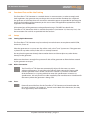
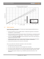
The application of RF current to biological tissue causes heating of the tissue. The higher the
RF current density in the biological tissue (current per unit area), the higher the resulting
temperature. The tissue stops reacting to electrical stimulation when heated above a threshold
over a minimal period of time.
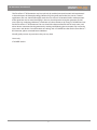
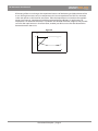
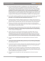
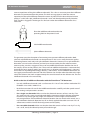
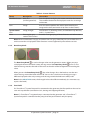
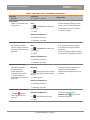
The extent of heating is proportional to the RF power (current density) output. A low RF power
output causes slow heating to the tissue (see Figure 1).
Figure 1
Figure 2
H2O
H2O
T=70°
H2O
H2O
T>70°
H2O
H2O
At high RF power output, the tissue can heat rapidly. Excessively high RF power output can
overheat the tissue, causing evaporation of the water bound in the tissue (see Figure 2). This can
result in charring of the tissue. Therefore, excessively high RF power output is not recommended.
Charring reduces the energy delivery to the heart tissue, which can cause other side effects
such as thrombosis or adhesions on the ablation electrode. It is recommended that ablation be
performed using a moderate effective RF power setting.
A lesion (conversion of the soluble protein in the tissue into a denatured, coagulated state) arises
when the tissue is exposed to RF current densities. At low current densities, the tissue is heated
slowly and contracts as a result of fluid loss. When the tissue is exposed to excessively high RF
current densities, the tissue fluid evaporates so rapidly that the resulting steam pressure in the
cells destroys the cell membrane. If this process occurs suddenly (superheating), it is perceptible
as a steam explosion. Since this phenomenon is audible in certain cases and under some
circumstances can be felt at the catheter handle, it is also known as “pop.” In extreme cases, this
can lead to undesirable tissue changes such as tears, craters, and holes. A suitable choice of RF
energy output and sufficient contact between the ablation electrode and the myocardial wall
avoids this pop effect.
1 Functional Principles | Page 1
RF Generator User Manual
1.2
Power Controlled Ablation Method
As described in Section 1.1, Functional Principles of RF Ablation, a high RF current can rapidly
heat the tissue. With the power controlled ablation method, the RF power output can be
manually adjusted on the basis of values known from experience.
The power adjusted by the user in this mode is the power output from the generator. The user
should be aware that the lesion formation is dependent on the RF current density in the specific
location in the tissue. This current density is a factor not only of the generator output, but also
of the ablation electrode surface area and the contact between the ablation electrode and the
cardiac tissue. In order to assess the effect of the RF power, the user must watch for intracardiac
ECG signal reduction in the area of the ablation.
1.3
Temperature Controlled Ablation Method
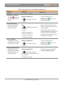
The temperature of the ablation electrode is measured by a temperature sensor. In the case of
non-irrigated ablation catheters, the temperature of the ablation electrode is an indication of the
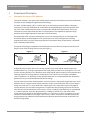
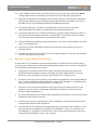
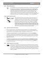
temperature of the tissue in contact with the electrode. During temperature controlled ablation,
the RF power output is regulated automatically by the generator so that the temperature
selected by the user is reached and maintained at the desired level (see Figure 3). Thus the risk of
charring, tissue adhesion, or pop is greatly reduced.
Figure 3
sec
The size of a lesion is determined primarily by the ablation time and temperature. With the
temperature controlled ablation method, it is not necessary to set the initial RF power level
manually.
Note: Because the ablation electrode measures only the temperature of the electrode with
its integrated temperature sensor and not the actual tissue temperature deep inside the
myocardium, tissue overheating can still occur. Therefore, temperature measurement is
suitable only for limiting overheating. However, in some physical circumstances, temperature
measurement may not prevent overheating. The temperature indicator is a guide, not an
absolute measurement.
1 Functional Principles | Page 2
RF Generator User Manual
The difference between actual tissue temperature and the temperature measured by the
integrated temperature sensor, moreover, depends greatly on the relevant catheter technology.
When standard catheters that are not irrigated are used, the deviation in temperature is
proportional to the electrode size (due to passive cooling by blood flow). The larger the ablation
electrode, the larger the temperature difference. Regardless of the electrode used, the actual
tissue temperature is the same as or higher than the indicated temperature. When an actively
cooled ablation electrode is used (for example, an irrigated electrode cooled with saline solution),
the electrode no longer provides a basis for accurate tissue temperature. In this case, the
temperature measurement is an indicator of the irrigation function and is completely dissociated
from the tissue temperature.
1.4
Unipolar Application Method
To perform ablation with RF current, a closed circuit is required. The RF current flows from the
generator via the connection cable to the catheter’s ablation electrode (tip electrode). The
current then passes through the biological tissue and is passed back to the generator through
a second electrode (indifferent electrode). In order for the tissue heating to occur at only the
interface between the ablation electrode and the tissue, the second electrode must have a
considerably larger surface area than the ablation electrode. This arrangement is known as a
unipolar application.
Because the current density is highest at the smaller ablation electrode, most of the RF energy is
converted into heat in the area of this electrode. The second, considerably larger RF electrode, is
preferably a skin-adhesive electrode. This second electrode is known as an indifferent electrode
or a neutral electrode. For safety reasons, care must be taken to ensure that the area of the
indifferent electrode is considerably larger than the area of the ablation electrode. If the ratio
between the electrodes is too small, severe skin burns can occur at the site of the indifferent
electrode. With this type of application, the information provided by the manufacturer of the
indifferent electrode and the information in Chapter 3, Warnings and Precautions, must be
heeded.
1.5
Measuring Impedance
Measurement of tissue impedance (the electrical resistance in the tissue) is used for two
purposes:
1.
To differentiate between the various types of tissue so that the ablation electrode can be
positioned correctly.
2.
To confirm that a lesion is being formed during RF current application.
The SmartAblate™ RF Generator measures impedance between the surface of the ablation
electrode and the indifferent electrode.
1 Functional Principles | Page 3
RF Generator User Manual
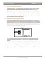
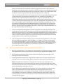
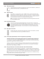
RF heating of the tissue changes the impedance because of the heating and dehydration of the
tissue. During the increase in tissue temperature, the tissue impedance first falls to a minimum
value and remains at this level for some time. Then the impedance rises based on the supplied
power (see Figure 4). Impedance should be monitored during ablation. A rapid increase in
impedance is an indicator that there is a problem and ablation should be stopped. One possible
cause for the rapid increase is char formation; another possible cause is that the electrode has
become buried in the tissue.
Figure 4
°C
ohm
70
°C
ohm
sec
1 Functional Principles | Page 4
RF Generator User Manual
2
Indications
The use of the SmartAblate™ RF Generator and all accessories is indicated in combination with
compatible therapeutic catheters for use in conventional intracardiac RF ablation procedures.
Read and follow the instructions for use that are provided in this user manual before using
the system in a clinical application. Also refer to instructions for use that are supplied with the
accessories and with the compatible therapeutic catheters.
2 Indications | Page 5
RF Generator User Manual
3
Warnings and Precautions
3.1
Warnings: Generator Usage
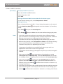
1.
Read this user manual carefully before using the SmartAblate™ RF Generator for the first
time. Note especially the instructions in Section 4.5, Setup.
2.
Cardiac ablation procedures should be performed only by physicians who have been
thoroughly trained in RF catheter ablation techniques. Catheter ablations should be
performed only in medical rooms in compliance with IEC/EC 60601-1, Annex A.4, Clause 16.
3.
In catheter ablation procedures, fluoroscopy is commonly used. When using fluoroscopy,
there is the risk of exposure to considerable radiation. The intensity of the X-rays and the
duration of the radiation can lead to acute radiation damage or to an increased risk of a
physical or genetic defects for both patients and medical personnel. Therefore, perform
catheter ablations only after carefully considering the potential radiation dose. The
advantages and disadvantages of X-ray exposure should be considered carefully before
catheter ablation is performed in pregnant women. Also, the long-term risk of prolonged
X-ray imaging has not been researched. Therefore, the advantages and disadvantages
should be considered carefully before this procedure is performed in prepubertal children.
Consider using a navigation system without fluoroscopy to reduce exposure to X-rays.
4.
Do not apply RF energy while a stimulator is connected to the generator unless specifically
indicated by the stimulator’s instructions for use. Doing so might induce ventricular
fibrillation.
5.
Always verify that the generator’s visual and acoustic alarms are working before using the
generator (see Section 6.1.1, System Startup).
6.
When the generator has been turned off, power continues to be supplied to the generator
through the mains cable. To completely cut off power to the generator, disconnect the
mains cable from the generator. To allow easy disconnection in the event of severe power
failure, make sure that the generator is located where there is easy access to the mains cable
on the back of the generator.
7.
After turning on the generator, always wait until the automatic self test has been
successfully completed before starting the first steps of the procedure on the patient (for
example, before anesthesia or before creating percutaneous access). Also, if using a remote
control, a pump, a Carto® System, or an electrophysiology recording system, verify that the
connections to those systems are functional prior to starting the first steps of the procedure.
Doing this helps to detect problems with the device before the patient is in a phase of the
intervention in which interruption could lead to an increased risk to the patient’s health.
Also perform a visual inspection of the accessories (see Section 5.3, Caring for Accessories).
8.
Use only catheters that have been approved for use with the maximum voltage specified in
this user manual (see Section 8.1, Specifications).
9.
Use only accessories that have been provided by or recommended by the generator’s
manufacturer (see Chapter 5, Accessories). The use of other accessories can have a negative
effect on the technical specifications. Do not modify accessories. Visually inspect all
accessories on a regular basis. Make sure that the connected cables are not damaged. When
using sterile accessories, be sure to maintain the sterility of those accessories.
3 Warnings and Precautions | Page 6
RF Generator User Manual
10. Place the generator on a secure, non-slip surface such as the Carto® System cart. If the
generator is placed on a mounting plate, make sure it is securely fastened. Do not place the
generator directly above another device and do not place any other device directly on the
generator. Make sure that there is enough free space on all sides of the generator to allow
the heat created by the generator to escape.
11. The entire surface of the indifferent electrode must be as close as possible to the operating
field and must have fully reliable contact with the patient’s body. The skin surface must be
free of excessive oil and body hair. (See Section 3.3, Warnings and Precautions: During an
Ablation Procedure.)
12. The generator is equipped with a contact quality monitoring feature for split indifferent
electrodes. If the contact quality falls below a defined value, the generator displays an alert
message. However, if two split indifferent electrodes are used at the same time and one
loses contact quality but the other maintains contact quality, no alert is triggered. If a solid
indifferent electrode detaches from the patient’s skin, no alert is triggered. When using a
solid indifferent electrode, the hospital staff is responsible for ensuring proper contact of the
electrode with the patient’s skin.
13. The patient must not be in contact with grounded metal components or with metal
components that have a large grounded area (for example, the operating table supports).
For this purpose, the use of sufficiently insulating antistatic covers on the operating table
is recommended. Electrostatic discharge (ESD) can give rise to extremely high current
densities at the catheter tip, which can injure the patient. Therefore, do not touch the pins
in the plug at the end of the catheter or the pins in the plug at the end of the cable after the
catheter has been placed in the patient’s body.
14. Skin contact between parts of the patient’s body (for example, between the arms and the
body) should not occur. Such contact can be avoided by using dry gauze, for example.
15. If the generator and physiological monitoring devices are used on a patient at the same
time, all monitoring electrodes without protective resistances or RF filters should be applied
to the patient’s body as far away as possible from the ablation electrodes. Needle electrodes
are not recommended for monitoring purposes. In all cases, it is appropriate to use
monitoring electrodes and other monitoring devices that limit the RF current.
16. Position the connection cables of the ablation electrodes in such a way that they do not
touch either the patient or other cables. Keep active electrodes that are temporarily not in
use at a safe distance from the patient.
17. Set the RF power at only moderate output to avoid charring and clotting at the catheter
ablation electrode.
18. When the SmartAblate™ RF Generator is used with irrigated catheters, monitor the irrigation
flow rate to avoid hazards caused by insufficient irrigation flow. The approximate flow
rate can be estimated by observing the drip speed in the drip chamber. The hospital staff
is responsible for determining and monitoring the flow rate to avoid insufficient flow of
the irrigation solution. The hospital staff is responsible for monitoring the total amount of
solution delivered to the patient to avoid an excessive loading of the irrigation solution in
the patient. For recommended flow rates, refer to the catheter’s instructions for use.
3 Warnings and Precautions | Page 7
RF Generator User Manual
19. Avoid using flammable anesthetics or oxidizing gases such as nitrous oxide (N2O) and
oxygen (O2) if the procedure is being performed in the region of the thorax or head,
unless the gases are being aspirated off or an anesthesia-safe device is being used. Before
starting RF ablation, allow time for flammable substances that are used as cleaning agents,
disinfectants, or solvents to evaporate. There is a risk associated with flammable liquids
under the patient or in the patient’s body cavities. Wipe away the liquid in these places away
before the generator is turned on. Beware of flammable endogenous gases. Materials such
as cotton and gauze, when saturated with oxygen, can be ignited by sparks that arise even
during normal use of the generator. (The foot pedal is suitable for use in operating rooms.)
20. Be aware during ablation procedures that in patients with cardiac pacemakers or pacemaker
leads, there is a risk of interference with the pacemaker function or damage to the
pacemaker. In case of doubt, consult the manufacturer of the device.
21. The electromagnetic radiation emitted by the generator can interfere with the function of
other electrical devices. Conversely, other electrical devices can influence the function of the
generator if they are operated at the same time in the immediate vicinity of the generator.
22. The plugs on the catheter and the catheter connection cable must not be brought into
contact with parts that have high voltage (such as mains outlets) or metallic objects. This can
lead to the patient’s death by electrocution.
23. To avoid damage to the connection cables, do not wrap the cables around the generator or
other apparatus. Coiling the connection cables during normal operation of the generator
creates inductive components, which can lead to measurement errors. The values indicated
in error can lead to misinterpretations.
24. Special safety measures with regard to electromagnetic compatibility (EMC) must be
taken with electrical medical devices. This equipment generates, uses, and can radiate
radiofrequency energy and, if not installed and used in accordance with this user manual,
may cause harmful interference to radio communications. Similarly, portable and mobile
communication devices may cause harmful interference to the functioning of the generator.
25. If error messages repeatedly appear, stop using the generator and contact Customer
Support.
26. To avoid damage to the generator and its accessories, use only appropriate cleaning agents
(see Sections 4.6, Cleaning and Disinfecting the Generator, and 5.4, Cleaning, Disinfecting,
and Sterilizing Accessories).
27. To avoid the risk of electric shock, connect the mains cable from the generator mains socket
(see Item 6 in Section 4.3, Controls on the Back of the Generator) to a 3-prong outlet that
meets the specifications in Section 8.1, Specifications.
28. The generator may be opened only by persons authorized by the manufacturer. When the
generator is open, parts that have high voltage or are very hot are accessible and can cause
injury. If the generator is opened by an unauthorized person, any claims on the warranty are
void. No modification of the generator is permitted.
29. If fluid penetrates into the generator, stop using the generator and contact Customer
Support.
3 Warnings and Precautions | Page 8
RF Generator User Manual
30. In the unlikely event that there is a fatal system error (the system will stop and the Alarm
indicator will flash red), immediately disconnect the mains cable from the generator.
31. Electrodes and probes for monitoring and stimulation devices can be electrical conductors
of RF current. Reduce the risk of burns by placing the electrodes and probes as far away as
possible from the site of ablation and from the indifferent electrode.
32. To avoid possible injury to patients and medical personnel, do not start RF power
application before the catheter is positioned in the intended ablation area.
33. To minimize electrical noise on the ECG recordings, position catheter connection cables so
that they do not touch either the patient or other cables. For an optimal ECG trace, keep
unused active surface electrodes at a distance from the patient.
34. To prevent fluid from impairing system performance, ensure that sterile catheters and cable
plugs are completely dry.
35. To prevent a system malfunction, inspect all reusable accessories regularly. Do not use
damaged cables.
36. Ablation data stored electronically must not be used for diagnosis or therapy. The intended
use is for archiving or research only.
3.2
Warnings: System Safety and Connections
The SmartAblate™ RF Generator can be connected directly or indirectly to many other devices
and accessories. The generator and the connected group of devices and accessories are referred
to in the following warnings as the “system.”
1.
The generator connections for the ECG signals and for the stimulator are galvanically
connected with the ablation catheter. Only cables and plugs approved for a CF type of
device (CF safety classification) may be used (see Section 5.2, Accessory Lists).
2.
All devices with these cables and plugs must fulfill the requirements stated in MDD/MPG for
class 1 devices. Fulfillment of the requirements stated in IEC/EN 60601‑1-1 and MDD 93/42/
EEC must be monitored and documented in a suitable way.
3.
The person who connects the generator and accessories to each other or who uses the
generator and accessories is responsible and liable for installation and operation that
complies with IEC/EN 60601‑1‑1.
4.
All system components must comply with all applicable requirements and standards and be
labeled pursuant to these standards.
5.
If there are any concerns regarding the use of a component, contact the distributor of the
component to obtain further information.
6.
If several devices are connected to the generator and to each other, they should be as safe,
both individually and together, as specified in IEC/EN 60601-1 and its sub-standards and
IEC/EN 60601‑1‑2. All devices and accessories, when located within the patient area, must
comply with IEC/EN 60601‑1 and its sub-standards.
3 Warnings and Precautions | Page 9
RF Generator User Manual
Keep in mind that the ECG connection cable for the generator creates a direct electrical
connection to the patient’s heart. Incorrect use of this connection can endanger the patient’s
life. Make sure that the leakage current of the connected system (in any combination) never
exceeds the maximum permissible value (patient leakage current ≤ 0.05 mA).
Take into account that the system’s RF leakage current can be negatively influenced by other
system components. The maximum allowable values are specified in IEC/EN 60601‑2‑2.
Displacements of the ECG baseline surface signals is a sign of uncontrolled RF current
leakage through the body surface ECG electrodes. Heating of these electrodes gives rise to
a shift in direct current voltage which, in turn, leads to a displacement of the baseline. In this
case, check the whole system combination to avoid uncontrolled current leakage. It may
also be the case, however, that the electrocardiograph is unsuitable for this use or that the
body surface ECG electrodes have too high a contact impedance. Make sure that the ECG
device is appropriate for this application. Skin burns at the body surface ECG electrodes can
be a sign of uncontrolled current leakage.
3.3
7.
There are many electrocardiographs to which a stimulator can be directly connected. The
stimulator must be galvanically isolated (or physically disconnected) before the RF current is
turned on. The reason for this is the parallel connection between the output of the generator
and the stimulator. If the connection is not isolated, the stimulator’s patient interface and
safety insulation may be damaged. The transfer of RF energy into the electrodes connected
to the stimulator can also cause injury to the patient.
8.
Only classified electrical medical devices may be connected to the generator. If a PC system
does not fulfill the requirements of IEC/EN 60601‑1 / UL 60601-1 and their sub-standards,
the distance between the PC system and the patient must be at least 1.83 m (6 ft) and the
PC system must fulfill the requirements of IEC 950 / UL 60950-1. All medical devices that are
connected electrically to the generator must fulfill the requirements of IEC/EN 60601‑1‑1,
the standard for medical systems.
Warnings and Precautions: During an Ablation Procedure
1.
Blood vessel perforation is a risk inherent in the placement of an electrophysiology catheter.
The catheter needs to be moved carefully to avoid damage or perforation of blood vessels.
2.
When performing ablation of the posterior wall of the left atrium, beware of the risk of
forming a lesion in the esophagus.
3.
Avoid high ablation temperatures. High ablation temperatures can lead to clot formation,
charring of the heart tissue or blood, and/or evaporation of interstitial intracellular fluid.
Note: The temperature indicated on the generator is not the tissue temperature. The
indicated temperature is the temperature of the catheter’s ablation electrode, which does
not necessarily represent the tissue temperature. This applies especially when catheters with
saline-cooled ablation electrodes are used.
When catheters with cooled ablation electrodes are used, the temperature measurement
reflects the temperature of the cooled electrode, not the temperature of the tissue.
The temperature of the tissue may be distinctly higher and the risk of pop (explosion of
steam bubbles) may increase. Therefore, use only moderate RF power output. Follow the
recommendations in the instructions for use provided with the therapeutic catheters that
are used with the system.
3 Warnings and Precautions | Page 10
RF Generator User Manual
4.
Keep in mind when setting the temperature that only the temperature of the electrode and
not the temperature of the heart tissue is measured. Because of the cooling effect of blood
flow, the temperature of the heart tissue may be higher than the temperature measured at
the ablation electrode.
5.
Avoid sudden increases in impedance to minimize charring at the ablation electrode.
Charring at the ablation electrode can result in reduced RF energy delivery and/or an
embolism.
6.
Make sure that the active RF electrode of the ablation catheter is not in contact with another
catheter or with another metallic conductor, such as an implanted pacemaker lead. This
could lead to uncontrolled conduction of the RF energy to other parts of the body, or to an
uncontrolled increase in the effective size of the active RF electrode.
7.
Do not set any extreme, unrealistic limit values. The limit values serve to trigger an alarm
when a limit value is exceeded. If unrealistic values are set, important alarm functions will be
triggered too late or not at all.
8.
To minimize the risk to the patient, keep the ablation duration to one minute or less.
9.
When using the usual operating settings, a low output RF power or a problem with the
ablation device can be a sign that the indifferent electrode is not correctly positioned or has
poor contact with its connection cable.
10. Continuously monitor the generator’s impedance measurement during RF energy
application. If a sudden increase in impedance is observed, stop the RF energy delivery.
Remove the catheter from the patient’s body and clean the ablation electrode of the
catheter with a sterile cloth to remove any adherent materials.
11. If there is any doubt about an unintended increase in RF energy or the proper functioning
of the touch screen, Data Entry Knob , foot pedal, or remote control during RF delivery,
immediately stop the RF energy delivery by pressing the Stop button on the generator,
releasing the foot pedal, or pressing the Stand-by button. If none of these measures
stops the RF energy delivery, disconnect the mains cable from the generator.
3.4
Handling Indifferent Electrodes
An indifferent electrode is used for unipolar ablations (see Section 1.4, Unipolar Application
Method).
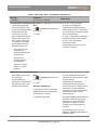
The indifferent electrode is monitored at all times by the generator.
•
To ensure patient protection, the generator prevents unipolar ablation in the absence of an
indifferent electrode.
•
If the indifferent electrode is not correctly connected to the generator, the generator immediately
stops RF energy delivery and displays a message.
•
The generator is equipped with a contact quality monitoring feature for split indifferent
electrodes. When a split indifferent electrode is used, the generator displays an alert message
as soon as skin contact with the electrode surface decreases by an unacceptable amount. After
the indifferent electrode is applied to the patient, the generator continuously monitors the
contact quality and updates an internal value for best achieved contact quality (the minimum
3 Warnings and Precautions | Page 11
RF Generator User Manual
contact impedance of the split indifferent electrode). This value is reset every time the indifferent
electrode is disconnected from the patient. The alert message appears when the contact
impedance of the split indifferent electrode increases by 40% from the best achieved contact
quality. If a solid (non-split) indifferent electrode is used and the electrode partially detaches
itself, no alert is triggered. The danger of a skin burn under the indifferent electrode is thus
increased.
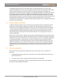
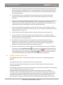
Place the indifferent electrode within the
operating field on the patient’s back.
Solid indifferent electrode
Split indifferent electrode
The generator provides the option of connecting two separate indifferent electrodes. Both
split and solid indifferent electrodes can be connected. In this case as well, the contact quality
monitoring feature works only with split indifferent electrodes. However, if two split indifferent
electrodes are used at the same time and one loses contact quality but the other maintains
contact quality, no alert is triggered. The use of two indifferent electrodes doubles the size of
the contact surface on the patient’s skin. The use of two indifferent electrodes is recommended,
especially for heavy patients with a low muscle mass, in ablations with high output (> 50 watts),
and in the case of prolonged RF energy delivery (> 60 seconds). If two indifferent electrodes are
used, apply one electrode to the left side of the ablation site and the other electrode to the right
side of the ablation site, both at approximately the same distance from the ablation site. The two
indifferent electrodes must not overlap.
Guide to the Use of Indifferent Electrodes with the SmartAblate™ RF Generator
•
Use only indifferent electrodes with a surface area of ≥ 124 cm² that conform with either IEC/
EN 60601‑2‑2 or ANSI / AAMI HF‑18.
•
Read the instructions for use for the indifferent electrodes carefully and take special note of
the warnings and precautions sections.
•
For a single-use electrode: Make sure that the electrode contact surface is not dry. If it is
dry, replace it with a new, unused electrode before continuing with the ablation procedure.
Do not use any contact gel with single-use electrodes. Use the single-use electrode for
only one procedure. If the indifferent electrode becomes loose or needs to be moved, use a
new indifferent electrode. Repeated use of an already applied electrode can mean a loss of
adhesiveness and thus lead to distinctly poorer contact quality.
•
For a reusable electrode: Make sure that the electrode contact surface is not dry. If it is dry,
use a small, evenly distributed quantity of conductive gel.
3 Warnings and Precautions | Page 12
RF Generator User Manual
•
Carefully select the contact area: Choose a muscular area on the back of the patient that is
as near the heart as possible and that has sufficient blood flow. Do not place the indifferent
electrode near wounds.
•
Carefully prepare the contact area: Prepare the contact area on the patient and on the
indifferent electrode according to the instructions for use provided with the indifferent
electrode. Place the indifferent electrode closer to the ablation site than any ECG electrode or
other products that could represent an alternative lead. Shave and degrease the skin.
•
Carefully apply the indifferent electrode to the contact area: Make sure that the whole
surface of the indifferent electrode forms a closed contact with the patient’s back. There
should be no pockets of air between the skin and the indifferent electrode. Oil, hair, dirt,
repeatedly used adhesive electrodes, and electrodes of low quality can impair contact quality
and increase the risk of a skin burn.
•
Heat produced by thermal blankets or other sources of heat adds to the heat arising under
the indifferent electrode. This increases the risk of skin burns. Do not use such sources of heat
in immediate proximity to the indifferent electrode.
WARNING
An unsuitable indifferent electrode or an incorrectly applied indifferent electrode can lead to
burns on the skin surface. Check the indifferent electrode and the connection cable before use.
Do not use these if they are damaged or modified.
3 Warnings and Precautions | Page 13
RF Generator User Manual
4
System Overview and Setup
4.1
Structure and Features
The SmartAblate™ RF Generator is a radiofrequency generator designed for use in cardiac
ablation procedures. The generator can be configured to work with a variety of other devices and
meets the highest standards for safety, precision, and ease of operation.
(The Esophageal Probe shown above is not applicable for the US and JP versions of the generator.)
The generator is compatible with a large number of catheters and devices. For a listing of devices
and accessories, see Section 5.2, Accessory Lists.
The generator is operated via an easy-to-use user interface. Selections can be made on the screen
by touching it (even when wearing surgical gloves) or by tapping it with a pen.
The generator features redundant protection circuits (if one safety mechanism fails, a second
safety mechanism indicates the failure to ensure safety). A central computer processor operates
the device. Several other microprocessors control the various functions, such as RF power
output and calculation of impedance. The generator is equipped with a memory unit that stores
the settings even after the generator has been turned off. These settings are active when the
generator is turned on again. Operating errors and defects in the attached devices are detected
and error messages are issued. For a list of possible error messages, see Sections 7.2, Warnings,
Alerts, and Ablation Stop Reasons and 7.3, System Errors.
4 System Overview and Setup | Page 14
RF Generator User Manual
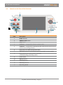
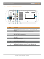
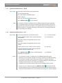
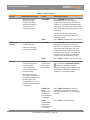
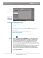
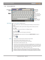
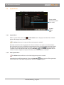
4.2
Controls on the Front of the Generator
1
2
3
13
4
5
6
12
7
11
8
Item
9
10
Description
1
RF On indicator
2
Ablation Start button
3
Stop button
4
Catheter 1 – receptacle for ablation catheter cable
5
Catheter 2 – receptacle for esophageal probe cable (not functional in the US
and JP versions of the generator)
6
Receptacles for indifferent electrode cables
7
Tilt Panel button (on side of front panel) (not available on some models)
8
Receptacle for ECG cable (external stimulator
/electrophysiology recording system)
9
Touch screen
10
Alarm indicator
11
Stand-by button
12
Stand-by indicator
13
Data Entry Knob
4 System Overview and Setup | Page 15
RF Generator User Manual
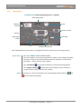
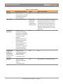
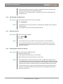
4.3
Controls on the Back of the Generator
3
2
1
4
5
6
7
DEVICE LABEL
9
8
Item
10
11
13
12
Description
1
Remote Control – Receptacle for SmartAblate™ Remote Control cable
2
USB port
3
Serial data port 1 – for electrophysiology recording system
4
Mains rating label
5
Fiber optic ports (not implemented)
6
Mains socket
7
Fuse cover
8
Potential equalization port
9
Serial data port 2 – for Carto® System
10
Ethernet port (not implemented)
11
Pump – Receptacle for SmartAblate™ Irrigation Pump cable
12
Foot Pedal – Receptacle for SmartAblate™ System foot pedal cable
13
Device label
4 System Overview and Setup | Page 16
RF Generator User Manual
4.4
Functional Test and On-Site Training
The SmartAblate™ RF Generator is a medical device. In some countries, in order to comply with
local regulations, the generator may not be put into service until the distributor has subjected
the generator to a functional test on site and has trained the person responsible for operating the
device in the handling of the generator per this user manual. All applicable requirements of local
regulations must be followed.
A functional test of the generator can be performed using a STOCKERT test box for the
SmartAblate™ RF Generator, which is available for purchase (see Section 5.2, Accessory Lists). See
the instructions for use that are provided with the test box.
4.5
Setup
4.5.1 Setting Up the Generator
The SmartAblate™ RF Generator may be used only in medical rooms in compliance with IEC/EN,
Annex A.4, Clause 16.
Place the generator on a secure, non-slip surface such as the Carto® System cart. If the generator
is placed on any other surface, make sure it is securely fastened.
Do not place the generator directly above another device and do not place any other device
directly on the generator.
Make sure that there is enough free space on all sides of the generator to allow the heat created
by the generator to escape.
4.5.2 Mains Connection
The SmartAblate™ RF Generator automatically adjusts for the necessary mains
voltage and frequency. To avoid the risk of electric shock, connect the mains cable
from the generator mains socket (see Item 6 in Section 4.3, Controls on the Back
of the Generator) to a 3-prong outlet that meets the specifications in Section 8.1,
Specifications. Use only the mains cable supplied by the manufacturer or distributor for
the country where the generator is being used.
4.5.3 Fuses
Externally accessible fuses for the SmartAblate™ RF Generator are located under the
fuse cover (see Item 7 in Section 4.3, Controls on the Back of the Generator). Use only
fuses approved by the manufacturer.
4 System Overview and Setup | Page 17
RF Generator User Manual
4.5.4 Potential Equalization
To avoid differences in potential between the generator and other devices with power
operation, the SmartAblate™ RF Generator must be connected to a grounding line
(as specified in IEC/EN 60601-1). Connect one end of the green and yellow potential
equalization cable provided with the generator to the grounding connection on
the back of the generator (see Item 8 in Section 4.3, Controls on the Back of the
Generator). Connect the other end to the room’s central grounding line. To avoid
radiation interference (noise) in the ECG signal, always use the same grounding line for
connection of all devices involved (electrocardiograph, Carto® System, generator).
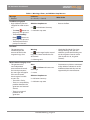
4.5.5 Circular Plug Connections
The circular plugs on the accessory cables are the same color as the
receptacles on the front and back of the generator (see Sections 4.2,
Controls on the Front of the Generator, and 4.3, Controls on the Back of
the Generator). To connect an accessory cable to the generator, align
the arrow on the plug with the mark on the receptacle and push in
without unnecessary force until a click indicates that the connector is
locked in the receptacle. If the plug does not fit in the receptacle, verify
that the color coding matches and that the number of pins in the plug is
appropriate for the receptacle. To remove the plug, gently pull back the
sleeve on the plug and pull the plug out of the receptacle.
4.5.6 Connection Cables and Catheters
Use only ablation catheters with temperature sensors and connection cables supplied by or
recommended by the manufacturer. Other catheters may be used only after consultation with
the distributor. For recommended accessories, see Section 5.2, Accessory Lists.
To connect an ablation catheter, use a sterile cable and connect one end to the Catheter 1
receptacle on the front of the generator (see Item 4 in Section 4.2, Controls on the Front of the
Generator) and the other end to the catheter. Alternatively, if the ablation catheter is connected
to an additional system, such as the Carto® System, connect the cable from the system to the
Catheter 1 receptacle.
To connect an esophageal probe, connect the appropriate cable to the Catheter 2 receptacle
on the front of the generator (see Item 5 in Section 4.2, Controls on the Front of the Generator).
(An esophageal probe cannot be used with the US or JP versions of the generator. The Catheter 2
receptacle is not functional.)
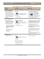
4.5.7 Indifferent Electrode Connections
The receptacles on the front of the generator for the indifferent electrodes (see Item
6 in Section 4.2, Controls on the Front of the Generator) can be used to connect both
solid and split indifferent electrodes. Some of the indifferent electrodes recommended
for use with the SmartAblate™ RF Generator are available with cables that have the
appropriate mating component. For other indifferent electrodes, appropriate adapter
cables are available.
4 System Overview and Setup | Page 18
RF Generator User Manual
4.5.8 Ethernet Connection
The Ethernet port on the back of the generator (see Item 10 in Section 4.3, Controls on
the Back of the Generator) is provided for future use.
4.5.9 USB Connection
Only USB mass storage devices (such as USB flash drives) may be connected to the
USB port on the back of the generator (see Item 2 in Section 4.3, Controls on the Back
of the Generator). Do not connect any other USB devices (such as a printer, mouse, or
scanner); these other devices are not supported by the generator.
Note: The USB ports on the back of the tilting front panel of the generator are for use
by service technicians only.
4.5.10 Serial Data Connections
Devices that exchange data with the generator, such as the Carto® 3 System, the
Carto® XP System, compatible electrophysiology recording systems, and other external
compatible monitoring systems can be connected to the serial data ports on the
back of the generator (see Items 3 and 9 in Section 4.3, Controls on the Back of the
Generator).
4.5.11 Fiber Optic Connections
The fiber optic ports on the back of the generator (see Item 5 in Section 4.3, Controls
on the Back of the Generator) are provided for future use.
4.5.12 Setting Up Irrigated Catheters with the Irrigation Pump and Tubing
Connect the SmartAblate™ RF Generator to the SmartAblate™ Irrigation Pump by plugging one
end of the connection cable into the Pump receptacle on the back of the generator (see Item
11 in Section 4.3, Controls on the Back of the Generator) and the other end of the cable into the
appropriate receptacle on the back of the pump.
Connect a SmartAblate™ Irrigation Tubing Set with the pump and with an irrigated catheter as
described in the SmartAblate™ Irrigation Pump user manual. Also see Section 6.6, Flushing to
Eliminate Air in the Tubing and Catheter.
4.5.13 Tilting the Generator’s Front Panel (Generators with a Tilt Panel button)
After the generator has been turned on (see Section 6.1.1, System Startup), the front panel can
be tilted for easier viewing. Press the Tilt Panel button (see Item 7 in Section 4.2, Controls on the
Front of the Generator) to release the lock and gently pull the bottom of the front panel forward.
Note: The generator’s front panel cannot be adjusted when the generator is off. Before moving
the generator, make sure that the front panel is closed.
4 System Overview and Setup | Page 19
RF Generator User Manual
4.5.14 Tilting the Generator’s Front Panel (Generators without a Tilt Panel button)
The front panel can be tilted for easier viewing (the generator does not have to be turned on).
Gently pull the bottom of the front panel forward until it is at the desired angle, then release it.
The front panel will lock into place. To lower the front panel, gently pull the front panel forward
slightly and then let it glide backward.
4.6
Cleaning and Disinfecting the Generator
WARNINGS
• The SmartAblate™ RF Generator must be turned off and the mains cable must be
disconnected from the generator before cleaning and disinfecting the generator.
• The SmartAblate™ RF Generator, mains cable, grounding cable, serial connection cable, and
the indifferent electrode cable must not be sterilized. Note: Some accessories may need
sterilization; follow the instructions for use that are provided with the accessories.
Use a dry microfiber cloth to clean the generator’s touch screen. If damp cleaning is necessary,
moisten a soft cotton or linen cloth with commercial glass cleaner that does not contain alcohol
and wipe the screen. Do not spray the cleaner directly onto the screen.
Use a soft, damp, lint-free cloth to clean and disinfect the housing of the generator. Use only nonflammable and non-explosive substances. Water or soapy water is recommended for cleaning.
Make sure that no liquid penetrates the inside of the generator.
The following disinfectants may be used for disinfecting the generator and its cables:
• Lysoformin® spezial
• Kodan®
• Meliseptol®
• Commercial disinfectants that do not contain ethyl alcohol
Caution: The following substances must not be used: acetone, benzene, acids of any kind
(including acetic acid and citric acid), scouring agents, nitro dilutions and other organic solvents.
Do not use any agent containing ethyl alcohol to clean the generator. Iodine or disinfectants
containing dyes cause discoloration of the housing and should not be used. Perform disinfection
by wiping, not by spraying. Avoid condensation. If cleaning or disinfecting the generator with
flammable or explosive substances cannot be avoided, make sure these substances have
completely evaporated before the generator is turned on.
Check the vents on the bottom and sides of the generator regularly for excessive deposits of dust
and foreign bodies. Carefully brush or wipe off the unwanted material.
4.7
Protecting Against Damage
In addition to being operated and maintained per the instructions in this user manual, the
SmartAblate™ RF Generator must also be protected against damage. This includes installing the
generator in a safe location and protecting the generator against moisture, contamination, and
contact with flammable or explosive substances.
Make sure that all cables to devices and accessories are arranged in a way that prevents tripping.
4 System Overview and Setup | Page 20
RF Generator User Manual
Make sure that the front panel of the generator is closed before moving the generator. Hold the
sides of the generator, not the front panel, when lifting the generator. Carry the generator with
two hands. To transport the generator over long distances or to send the generator for service,
use the original packaging. If the original packaging is not available, contact the manufacturer or
distributor for a replacement.
4.8
Disposal
Inadequately treated electrical and electronic waste poses environmental and health risks. Follow
local regulations for disposal of the SmartAblate™ RF Generator and its electrical or electronic
accessories. To ensure proper disposal, there is also the option of contacting your Biosense
Webster representative regarding return of the generator and its accessories.
4 System Overview and Setup | Page 21
RF Generator User Manual
5
Accessories
5.1
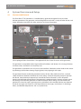
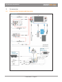
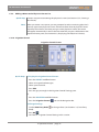
Diagram of the Generator and Accessories
Patient Area
1
2
3
4
10
5
8
9
11
6
7
Front View
Back View
12
Outside
Patient Area
13
Outside
Patient Area
18
14
17
16
15
5 Accessories | Page 22
RF Generator User Manual
Item
5.2
Description
1
SmartAblate™ RF Generator
2
Catheter
3
Carto® 3 System
4
Catheter
5
Carto® XP System
6
Catheter
7
Esophageal probe (not applicable for the US and JP versions of the
generator)
8
ECG connection
9
Split indifferent electrode
10
Split indifferent electrode
11
Erbe indifferent electrode
12
SmartAblate™ Irrigation Pump
13
SmartAblate™ Remote Control
14
Foot pedal
15
Grounding cable
16
Mains cable
17
Personal computer or Carto® System
18
Electrophysiology recording system
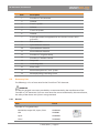
Accessory Lists
The following is a list of accessories for the SmartAblate™ RF Generator.
WARNING
Use only the original accessories provided by or recommended by the manufacturer of the
SmartAblate™ RF Generator. If you use accessories that are not authorized by the manufacturer,
the safety of the device and system is not guaranteed.
5.2.1 Devices
Item
Part #
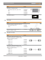
SmartAblate™ Irrigation Pump
Worldwide, except USA, Japan, China
M4900103
USA
M490003
Japan
M4900203
China
M4900403
5 Accessories | Page 23
RF Generator User Manual
Item
Part #
SmartAblate™ Remote Control
Worldwide, except USA, Japan, China
M4900104
USA
M490004
Japan
M4900204
China
M4900404
STOCKERT Testbox III
39F45X
RF
POWER
ECG SIMUL
ATION
THR
5.2.2 Foot Pedal
Item
Part #
Foot Pedal, length of connection cable: 3 m
Worldwide, except China
M490005
China
M4900405
Foot Pedal Extension Cable, length: 7 m
(Redel‑6 à Redel‑6, black)
M490026
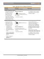
5.2.3 SmartAblate™ Cables
Item
Part #
Connection Cable from SmartAblate™ RF
Generator to SmartAblate™ Remote Control
(Redel‑10 à Redel‑10, yellow)
length: 10 m
M490010
length: 15 m
M490029
length: 25 m
M490012
length: 30 m
M490013
Connection Cable from SmartAblate™ RF
Generator to SmartAblate™ Irrigation Pump
(Redel‑10 à Redel‑10, blue)
length: 1 m
M490027
length: 3 m
M490016
length: 5 m
M490028
length: 10 m
M490030
5 Accessories | Page 24
TC
DS
INDIFFERENT
RF Generator User Manual
Item
Part #
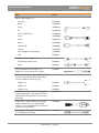
Mains Cable, length: 3 m
Australia
M4900601
Brazil
M4900609
China
M4900410
EU
M4900108
India / South Africa
M4900604
Israel
M4900606
Japan
M4900210
Russia
M4900603
Switzerland
M4900605
Taiwan
M4900607
UK / Singapore / Hong Kong
M4900602
USA
M490024
Grounding Cable, length: 3 m
Worldwide, except Japan
M490014
Japan
M490015
ECG Connection Cable, length: 3 m
(Redel‑16 à 4 x 2 mm tip pins, green)
M490018
Serial Data Communication Cable for Carto®
Systems or Electrophysiology Recording
Systems (Redel‑9 à Dsub‑9, gray)
length: 3 m
M490021
length: 5 m
M490025
length: 15 m
M490023
Connection Cable for Smiths Esophageal
Probe, Rectangular 2 pin, length: 3 m (not
applicable for the US and JP versions of the
generator)
M490019
Connection Cable for Philips Esophageal
Probe, accepts mini (1/8”) phone plug,
length: 3 m (not applicable for the US and JP
versions of the generator)
M490020
Connection Cable from STOCKERT Testbox III
to an indifferent electrode
M490017
—
5 Accessories | Page 25
RF Generator User Manual
Item
Part #
Connection Cable for CELSIUS® Catheters
(TC/THR, Redel 26 Redel 10, red), length:
3 m
D130302
Connection Cable for CELSIUS® Catheters
(DS, Redel 26 Redel 10, green), length: 3 m
D130303
Connection Cables from SmartAblate™ RF
Generator to ablation catheters (available in
Europe), length: 3 m
APTMedical Triguy-D
M4900622
Boston Scientific / EPT
M4900610
Osypka
M4900611
Osypka Easy-TC
M4900620
Osypka Plus Flutter
M4900619
Bard
M4900612
St Jude Medical / IBI
M4900613
St Jude Medical / DAIG
M4900614
Biotronik
M4900615
Medtronic
M4900616
5.2.4 Indifferent Electrodes and Cables available from STOCKERT GmbH
Other indifferent electrodes that meet the requirements specified in Section 3.4, Handling
Indifferent Electrodes, are also compatible with the SmartAblate™ RF Generator.
Item
Part #
Erbe Indifferent Electrode for Children,
reusable, 17 x 11 cm
39D-15X
Erbe Indifferent Electrode for Adults, reusable,
17.5 x 29.5 cm
39D-19X
Connection Cable for 3M Indifferent Electrode
with Clip, length: 3 m
M490035
Connection Cable for Erbe Indifferent
Electrode with 4-mm Phone Jack, length: 3 m
M490034
5.2.5 Catheters
For recommended catheters, contact Customer Support.
Note: The UL mark on this generator is only valid with accessories tested by Underwriters Laboratories.
See http://www.stockert.de/fileadmin/downloads/Tested_accessories_by_UL.pdf.
5 Accessories | Page 26
RF Generator User Manual
5.3
Caring for Accessories
WARNING
Do not modify any accessories.
5.3.1 Connection Cables
Visually inspect all connection cables before each use. Do not use damaged cables.
To avoid damage to the connection cables, do not wrap the cables around the generator or
other apparatus. Coiling the connection cables during normal operation of the generator creates
inductive components which can lead to measurement errors. The values indicated in error can
lead to misinterpretations.
When plugging in a cable or unplugging a cable, hold the cable by the plug housing, not by the
cable itself.
5.3.2 Indifferent Electrodes
Follow the instructions in Section 3.4, Handling Indifferent Electrodes, and the instructions for
use that are provided with the indifferent electrodes.
5.3.3 Foot Pedal
Never pick up the foot pedal by its cable. Do not coil the cable closely around the foot pedal.
Check the cable regularly for visible damage. Do not use a damaged foot pedal.
5.4
Cleaning, Disinfecting, and Sterilizing Accessories
To ensure that the accessories are safe to use, follow the cleaning, disinfecting, and sterilizing
instructions in the instructions for use provided with the accessories. Make sure that any liquid is
removed from electrical contacts after cleaning, disinfecting, or sterilizing.
.
5 Accessories | Page 27
RF Generator User Manual
6
Generator Operation
6.1
Quick Overview
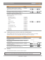
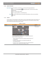
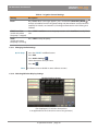
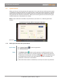
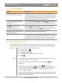
6.1.1 System Startup
Quick Steps
Connect the generator to the mains supply.
Press Stand-by to turn on the generator.
At the message, press Stop .
Optionally, turn on the remote control.
For irrigated catheters, set up and turn on the pump.
Notes
, make sure that Ablation Start 1. When you press Stand-by and the foot pedal are not pressed.
and Stop 2. When you turn on the generator, the generator’s audible and visual indicators
are tested to allow you to verify that they are functional. The Stand-by
indicator lights up and the SmartAblate™ System logo appears on the screen.
The Alarm indicator flashes alternately red and orange for a short time to
indicate that the Alarm indicator is working. Also, the RF On indicator flashes
orange and an audible RF tone is played briefly. If the indicators listed above
do not perform as described, there is a problem with the generator and you
should contact Customer Support.
3. Progress dots in the bottom left corner of the screen indicate that the system
is performing a self test. When the self test is successfully completed, a
confirmation message appears asking you to press Stop to continue. After
you press Stop , the Ablation screen will appear. If the progress dots do
not appear, or if the number of dots stops increasing and the logo remains on
the screen, or if the confirmation message does not appear, there could be a
problem (see Section 7.4, Other Troubleshooting).
4. Always wait until the automatic self test has been successfully completed
before starting the first steps of the procedure on the patient (for example,
before anesthesia or before creating percutaneous access). Also, if using a
remote control, a pump, a Carto® System, or an electrophysiology recording
system, verify that the connections to those systems are functional prior to
starting the first steps of the procedure. Doing this helps to detect problems
with the device before the patient is in a phase of the intervention in which
interruption could lead to an increased risk to the patient’s health. Also perform
a visual inspection of the accessories (see Section 5.3, Caring for Accessories).
6 Operation: Quick Overview | Page 28
RF Generator User Manual
6.1.2 System Shutdown
Quick Steps
Stop ablation (see Section 6.4.2, Starting and Stopping Ablation).
Press and hold Stand-by generator.
for approximately 3 seconds to turn off the
Turn off the remote control.
For irrigated catheters, turn off the pump.
Note
You can turn off the pump and remote control before or after you turn off the
generator.
6.1.3 Screens
The SmartAblate™ RF Generator has four primary screens, represented by the first four buttons on
the Navigation Bar. See Section 6.9, Flowchart of the Screens, for a chart that lists other screens
that can be accessed from these primary screens.
Table 1 – Screens
Screen
Description
Connections
Section
6.2,
Connections
(The Esophageal Probe shown above is not applicable for the US
and JP version of the generator.)
Shows all devices that you can connect to the SmartAblate™
RF Generator.
Indicates which devices are currently connected and
functioning properly.
Provides access to information about the connected devices.
Provides access to the System Settings screen.
6 Operation: Quick Overview | Page 29
RF Generator User Manual
Table 1 – Screens
Screen
Description
Section
Preset
6.3, Presets
Provides access to selecting, editing, creating, and deleting
presets.
Provides access to the Irrigation Control screen, the Audio
Settings screen, and the Display Settings screen.
Ablation
6.4, Ablation
When the Ablation screen is displayed, you can press
Ablation Start stop ablation.
and Stop or the foot pedal to start or
The screen displays ablation measurement information
and provides the ability to change common settings while
viewing the Ablation screen.
When the Navigation Bar is displayed with the Ablation
screen (before or after ablation), you can press Edit on the
Navigation Bar to change additional settings. You can press
Irrigation Control to modify irrigation settings for an
irrigated catheter. You can press System Control to
change the volume or the brightness of the screen and to
indicate whether the generator or remote control has control
of the system.
When ablation stops, the Ablation Summary appears.
6 Operation: Quick Overview | Page 30
RF Generator User Manual
Table 1 – Screens
Screen
Description
Section
Post
6.5, Post
Procedure
(The Max. Esophageal temperature shown above is not applicable
for the US and JP versions of the generator.)
Displays the Post (Post Procedure) screen.
6.1.4 Screen Features
Sample Screen (Preset Screen)
Button
Button
Icon
Pane
Selection buttons
Navigation Bar
Workflow buttons
Icons
System Status icon
Table 2 – Screen Features
Name
Description
How to Use
Button
Blue, raised
Press the button to display another screen or perform an
action.
Selection button
Gray, flat
(white when
selected)
Press one button to make a selection from a group of buttons.
6 Operation: Quick Overview | Page 31
RF Generator User Manual
Table 2 – Screen Features
Name
Description
How to Use
Workflow button
Black, flat
(on Navigation Bar)
Press the button to display the screen named on the button.
The workflow button for the displayed screen has an orange
underscore.
Icon
Image
Press the icon to perform the action represented by the
image on the icon (see Section 6.10, Icons on the Screens).
System Status
icon
Image, triangle
See Sections 7.2, Warnings, Alerts, and Ablation Stop Reasons,
and 7.3, System Errors.
Pane
Rectangular gray
section of the screen
Provides visual grouping of related buttons and information.
Note: When raised buttons are gray and when icons are gray, either they are not available for use
on the screen that is displayed or their functions are not supported by the software version.
6.1.5 Data Entry Knob
The Data Entry Knob is used to change values on the generator screens. When you press
a displayed value on the touch screen, the ring around the Data Entry Knob turns on. The
color of the ring matches the color of the value or the color of the background surrounding the
value.
When you turn the Data Entry Knob , the value changes. Press the knob to save the new
value. The ring around the knob will turn off. You can also save the new value by pressing a
different displayed value or by waiting until the ring around the knob turns off by itself.
Note: At the Ablation screen, the changed values take effect immediately (it is not necessary
to press the knob).
6.1.6 Foot Pedal
If a SmartAblate™ System foot pedal is connected to the generator, the foot pedal can be used to
start and stop ablation (see Section 6.4.2, Starting and Stopping Ablation).
Note: If a SmartAblate™ Irrigation Pump is connected to the generator and a SmartAblate™
System foot pedal is connected to the pump, that foot pedal controls only the pump.
6 Operation: Quick Overview | Page 32
RF Generator User Manual
6.1.7 Typical Procedure Process – Quick
Quick Steps
Physically connect devices to the generator.
Turn on the generator.
Press the Preset workflow button.
Select a preset.
Press the Ablation workflow button.
Press Ablation Start Note
to start ablation.
At a minimum, connect a catheter and an indifferent electrode to the generator.
For an irrigated catheter, also connect a pump with a flushed tubing set (see the
instructions for use for the SmartAblate™ Irrigation Pump, the instructions for use
for the SmartAblate™ Irrigation Tubing Set, and Section 6.6, Flushing to Eliminate
Air in the Tubing and Catheter.)
6.1.8 Typical Procedure Process – Full
Quick Steps
Turn on the generator and remote control.
(6.1.1, System Startup)
At the Connections screen, review the device
connections.
(6.2, Connections)
Physically connect all applicable devices to the
generator.
Physically connect all applicable devices to the
patient.
At the Preset screen, select or create a preset.
(6.3, Presets)
Go to the Ablation screen, then position the
catheter at the first ablation site.
or press and hold the foot
Press Ablation Start pedal to start ablation.
Notes
(6.4, Ablation)
1. At a minimum, connect a catheter and an indifferent electrode to the
generator. For an irrigated catheter, also connect a pump and a flushed tubing
set (see the instructions for use for the SmartAblate™ Irrigation Pump, the
instructions for use for the SmartAblate™ Irrigation Tubing Set, and Section 6.6,
Flushing to Eliminate Air in the Tubing and Catheter).
2. Optionally, connect other devices shown on the Connections screen.
on the front of the
3. You can also start ablation by pressing Ablation Start remote control or by pressing the foot pedal connected to the remote control
when the remote control is the system Master (see Section 6.7, System Control).
6 Operation: Quick Overview | Page 33
RF Generator User Manual
6.2
Connections
Connections Screen (Displaying Carto® 3 System)
Recording System
Pump
Mapping
System
Remote Control
Catheter
Esophageal
Probe
Foot Pedal
ECG
Indifferent Electrodes
(The Esophageal Probe shown above is not applicable for the US and JP versions of the generator.)
Quick Steps
Press the Connections workflow button.
Press the image for any device (except the ECG cable) to view information about
the device and/or to test the interface between the generator and the device
(see Table 3 – Device Screens in this section).
Press Front/Back to view the connections on the back of the generator.
to open the System Settings screen (see Table 4 –
Press System Settings System Settings Screen Options in this section).
Note
See Section 7.1, Device Connections, for an explanation of the meaning of
for each device connection.
6 Operation: Connections | Page 34
and
RF Generator User Manual
Sample Device Screen
Table 3 – Device Screens
Device
Information Displayed
Action
Action Description
Generator
Device name
N/A
N/A
Change
Press Change, then press the image
of the connected mapping system.
The mapping system image on the
Connections screen will change
when this screen closes.
Manufacturer
Serial number
Software and hardware
versions
Last and next preventive
maintenance dates
Customer name and
number
Mapping
System
(Carto® 3
System,
Carto® XP
System, or
Other)
Image of generator and
mapping system
6 Operation: Connections | Page 35
RF Generator User Manual
Table 3 – Device Screens
Device
Information Displayed
Action
Action Description
After selecting the
mapping system,
images and values
appear for verifying
transmission of
impedance data
TRANSMIT
Press TRANSMIT to test the
communication on the mapping
system connection port (see Item 9 in
Section 4.3, Controls on the Back of the
Generator). The color in the arrow moves
from left to right to indicate that the test
is running.
The number on the screen is the
impedance value being sent to the
mapping system.
Recording
System
Image of generator and
recording system
STOP
Press STOP to stop the transmission test.
TRANSMIT
Press TRANSMIT to test communication
through the recording system port
(see Item 3 in Section 4.3, Controls on
the Back of the Generator). The color
in the arrow moves from left to right
to indicate that the test is running. The
numbers on the screen are the values
being sent to the recording system.
STOP
Press STOP to stop the transmission test.
Flush
(active when
the pump is
connected)
Press Flush. When a message appears,
press and hold the Data Entry Knob to flush air bubbles from the
irrigation tubing and the catheter. Use
this function carefully! For details, see
Section 6.1.5, Data Entry Knob.
START Low
Flow
(visible when
the pump is
connected and
is stopped)
Press START Low Flow to start the
pump flowing at the low (standby)
flow rate (see Section 6.3.10, Irrigation
Control).
STOP
(visible when
the pump is
connected and
is running)
Press STOP to stop the pump.
Values for verifying
transmission of data
Pump
Active flow rate (or
dashes if the pump is
not connected)
Serial number (or
dashes if the pump is
not connected)
Message to connect
the pump and select an
irrigated catheter preset
(if the pump is not
connected or if a nonirrigated catheter preset
is selected.)
6 Operation: Connections | Page 36
RF Generator User Manual
Table 3 – Device Screens
Device
Information Displayed
Action
Action Description
Remote
Device name
N/A
N/A
Serial number (or dashes
if the remote control is
not connected)
Foot Pedal
Image of foot pedal
Foot pedal
test (for the
foot pedal
connected to
the generator)
Press the foot pedal connected to the
generator to verify that it is working.
During the foot pedal test, a tone is
emitted and the image changes to a
pressed foot pedal. RF energy is not
delivered during the foot pedal test
(while the Foot Pedal device screen is
displayed).
Indifferent
Electrode
Green bar and
number(s) indicating
impedance if indifferent
electrode is connected
and is functioning
properly
N/A
N/A
N/A
N/A
N/A
See Section 6.3.2, Selecting a Preset.
Red bar and dashes if
indifferent electrode is
not connected
Red bar and number(s)
if split indifferent
electrode is connected
but contact quality is
below the threshold
Esophageal
Probe (not
applicable for
the US and JP
versions of the
generator)
Temperature of
esophageal probe (or
dashes if there is no
probe attached)
Catheter
Type of catheter
selected on Preset
screen
Connection status
Connection status
6 Operation: Connections | Page 37
RF Generator User Manual
Table 4 – System Settings Screen Options
Information Displayed
Action
Date
Press a gray date button and use the Data Entry Knob date.
to change the
Time
Press a gray time button and use the Data Entry Knob time.
to change the
Language
Select a language (if supported by the software version).
Calibrate Touch Screen
button
Press Calibrate Touch Screen to improve the performance of the touch
screen (see Section 7.5, Calibrating the Touch Screen).
Service button
This button is for use by service technicians.
Export to USB button
Press Export to USB to export ablation and event log data to a USB flash
drive (see Section 6.5.1, Exporting Ablation and Event Log Data to a USB
Flash Drive).
6 Operation: Connections | Page 38
RF Generator User Manual
6.3
Presets
Preset Screen
Physician
Presets pane
Preset
pane
Catheter
pane
6.3.1 Preset Overview
• A preset is a named group of settings to use during ablation.
• The SmartAblate™ RF Generator comes with one standard preset for each catheter type listed
in the Catheter pane. This preset is always the first in the list and it cannot be deleted.
• You can create new presets for each physician.
• You can view a list of all of the presets for a selected catheter type, or you can view only the
presets for a selected physician for the selected catheter type.
• When you select a catheter type, the default for that catheter type is automatically selected.
You can designate one of the displayed presets to be the new default for the catheter type.
6.3.2 Selecting a Preset
Quick Steps
Press the Preset workflow button.
Select the catheter type.
Select a preset.
Notes
1. The currently selected preset is highlighted (white background).
2. The preset workflow button displays the name of the selected preset.
3. For instructions on displaying the presets for only one physician, see Section
6.3.8, Displaying One Physician’s Presets.
6 Operation: Presets | Page 39
RF Generator User Manual
6.3.3 Editing a Preset
Edit Preset Screen in Power Control Mode, Irrigated Catheter
Impedance
Settings pane
Ablation
Settings pane
Temperature
Settings pane
Irrigation Control
Settings pane
(appears only
for irrigated
catheters)
Normal and Fast
are only available
for 4mm catheters
Esophageal
Temperature
Settings pane
(The Esophageal Temperature Settings pane shown above
is not applicable for the US and JP versions of the generator.)
Edit Preset Screen in Temperature Control Mode, Non-Irrigated Catheter *
* Temperature Control Mode is not available for some irrigated catheters.
(Temperature Control Mode for irrigated catheters and
the Esophageal Temperature Settings pane are not
applicable for the US and JP versions of the generator.)
6 Operation: Presets | Page 40
RF Generator User Manual
EDITING A PRESET (continued)
Quick Steps
1) Display the Edit Preset Screen
Press the Preset workflow button.
Select the preset to edit.
Press Edit.
2) Change the Control Mode (not available for all catheter types)
In the Ablation Settings pane, select Temperature or Power.
3) Change Settings
Press a displayed value (see Table 5 – Preset Setting Descriptions in this section).
Use the Data Entry Knob Knob).
, then press In selected preset.
Press Save or
Press Escape Notes
to change the value (see Section 6.1.5, Data Entry
, then press No to exit the screen without changing the preset.
1. If you don’t see the preset that you want to edit, select a different catheter
type (see Section 6.3.2, Selecting a Preset) or display the presets for a different
physician (see Section 6.3.8, Displaying One Physician’s Presets).
2. The choices in each pane vary depending on the catheter type you select.
3. Before making changes, select Temperature or Power in the Ablation Settings
pane to select Temperature Control Mode or Power Control Mode. The
selections in the panes vary depending on the mode.
(Temperature Control Mode is not available for all catheter types and is not
applicable for the US and JP versions of the generator.)
4. The Irrigation Control Settings pane appears only when you select an irrigated
catheter.
, a message appears asking whether to save In
5. When you press Save selected preset or Save temporarily. Select In selected preset. (See Section
6.3.4, Editing a Preset – Temporary Save, for information on Save temporarily.)
and then press In selected preset, the selected
6. When you press Save preset is saved with the revised values. If you want to save the revisions as a
different preset, press Save As Creating a New Preset.
and follow the instructions in Section 6.3.5,
7. You cannot save changes to the standard presets that come with the generator.
If you make changes to a standard preset and want to save the changes, press
Save As and follow the instructions in Section 6.3.5, Creating a New Preset.
6 Operation: Presets | Page 41
RF Generator User Manual
Table 5 – Preset Setting Descriptions
Setting
Description
Ablation Settings Pane
Time
The time limit for a single ablation. Ablation will stop
automatically after this time.
Max. Power
(only in Temperature Control Mode) Upper power limit for
the temperature control algorithm. The temperature control
algorithm will automatically set the power without exceeding
this value. Consult the instructions for use for the catheter to
determine the appropriate power setting for the catheter.
Power
(only in Power Control Mode) The output power to be maintained
by the generator during the ablation. Consult the instructions for
use for the catheter to determine the appropriate power setting
for the catheter.
Power Ramp Duration
(only in Power Control Mode) The time it will take the generator
to increase power from 0W to the value set in the Power field.
Temperature Settings Pane
Target
(only in Temperature Control Mode) The temperature that you
want the ablation electrode to reach. The generator will generate
power up to the Max. Power setting in an attempt to reach the
Target temperature.
Warning
(only in Power Control Mode) The temperature of the ablation
electrode at which a warning will occur. RF energy will remain on.
Cut‑Off
The temperature of the ablation electrode at which RF energy will
automatically shut off.
Control Algorithm
(only for 4mm catheters in Temperature Control Mode) The
sensitivity of the temperature control algorithm to changes in
temperature; how fast it reacts/how aggressively it changes the
power to reach the target temperature.
Esophageal Temperature Settings Pane (not applicable for the US and JP versions of the generator)
Max.
Warning / Cut‑Off
Select either Warning or Cut‑Off.
If you select Warning, then select the temperature of the
esophageal probe at which you want a warning to occur. RF
energy will remain on.
If you select Cut‑Off, then select the temperature of the
esophageal probe at which RF energy will automatically shut off.
6 Operation: Presets | Page 42
RF Generator User Manual
Table 5 – Preset Setting Descriptions
Setting
Description
Rise
Warning / Cut‑Off
Select either Warning or Cut‑Off.
If you select Warning, then select the increase of temperature
of the esophageal probe at which you want a warning to occur
during ablation—the increase will be determined from a baseline
measurement taken just before ablation. RF energy will remain
on.
If you select Cut‑Off, then select the increase of temperature
of the esophageal probe at which RF energy will automatically
shut off—the increase will be determined from a baseline
measurement taken just before ablation.
Impedance Settings Pane
Max. Cut‑Off
The maximum impedance measurement between the ablation
electrode and the indifferent electrode above which RF energy
will automatically shut off.
Spike Cut‑Off
If the impedance spikes higher than the number set here in any
half second interval, the RF energy will automatically shut off.
Min. Cut‑Off
The lowest impedance measurement between the ablation
electrode and indifferent electrode below which the RF energy
will automatically shut off.
Irrigation Control Settings Pane
This pane appears only when an irrigated catheter type is selected (see Section 6.3.10,
Irrigation Control).
Other
Audio Settings See Section 6.3.11, Changing Audio Settings.
Display Settings See Section 6.3.12, Selecting Ablation Display Settings.
6 Operation: Presets | Page 43
RF Generator User Manual
6.3.4 Editing a Preset – Temporary Save
Preset Screen After Temporary Save
EDITED
PRESET*
indicates
temporary save
Asterisk (*) after
preset name
indicates
temporary save
of that preset
Quick Steps
1) Display the Edit Preset Screen
Press the PRESET workflow button.
Select the preset to edit.
Press Edit.
or
When the Ablation screen is displayed, press Edit on the Navigation Bar.
2) Edit the Preset
Follow the instructions in Section 6.3.3, Editing a Preset.
3) Save the Preset Temporarily
Press the Ablation workflow button or another workflow button.
or
Press Save Notes
, then press Save temporarily.
1. When you save temporarily, “EDITED PRESET*” is displayed above the list of
presets and none of the presets in the list is selected. To understand which
preset has been temporarily edited, look at the name of the preset on the
PRESET workflow button—the name will be followed by an asterisk (*).
2. Temporary changes are in effect only until a different preset is selected or the
system is turned off. When a different preset is selected, the temporary changes
to the previous preset are discarded.
3. The most common time to perform a temporary save is when you are preparing
to start ablation or during a pause in ablation when you determine that a
permanently saved preset does not contain the exact settings that you want.
4. To save the temporary preset as a new preset, follow the instructions in Section
6.3.5, Creating a New Preset.
5. All changes made at the ABLATION screen are temporary (see Section 6.4.3,
Making Temporary Changes to Ablation Settings).
6 Operation: Presets | Page 44
RF Generator User Manual
6.3.5 Creating a New Preset
Keyboard Screen
PHYSICIAN
NAME
Backspace
(erases one
character)
OK
(closes keyboard
and saves physician
name and preset
name)
PRESET
NAME
Escape
(closes keyboard
without saving)
Quick Steps
Press the Preset workflow button.
In the Catheter pane, select the catheter type for which you want to create a
preset.
In the Preset pane, select a preset with settings similar to those you want.
Press Edit.
Change the settings (see Section 6.3.3, Editing a Preset).
Press Save As .
Select a physician’s name, then type a preset name.
or
Press Create New, type a physician name, press PRESET NAME, then type a
preset name.
Press OK Notes
.
1. The physician’s name can be a maximum of 9 characters.
2. The maximum number of physician names is 10.
3. The preset name can be a maximum of 13 characters.
4. The maximum number of presets is 80.
5. You cannot use the same preset name for two catheter types. For example, you
cannot create an 8mm preset named “20W POWER LIMIT” if you already created
one with the same name for 4mm. For this reason, it is a good idea to include a
catheter description such as “4MM” in the preset name.
6. If there are fewer than 10 physician names in the Physician Presets list, the
physician’s name that you type when you create a new preset will be added to
the Physician Presets list (see Section 6.3.8, Displaying One Physician’s Presets).
6 Operation: Presets | Page 45
RF Generator User Manual
7. When you create a new preset, it will be available only for the catheter type
that you selected when you created the preset.
8. See Section 6.3.4, Editing a Preset – Temporary Save, for an explanation of a
temporary save.
6.3.6 Designating a Default Preset
Quick Steps
Select the preset that you want as the default.
Press Set Default.
Notes
1. The default preset is the preset that is automatically selected after you select a
catheter type.
2. “(D)” appears after the name of the default preset.
6.3.7 Deleting a Preset
Quick Steps
Select the preset to delete.
Press Delete .
Press Yes.
Notes
1. The standard presets that come with the generator cannot be deleted.
2. If you delete all of the presets for one physician, the physician’s name will
be deleted from the Physician Presets list (see Section 6.3.8, Displaying One
Physician’s Presets).
6.3.8 Displaying One Physician’s Presets
Quick Steps
Press the Preset workflow button.
Select the catheter type.
In the Physician Presets pane, press the button.
Select the physician whose presets you want to see.
Notes
1. When the button in the Physician Presets pane says All, all of the presets for
the catheter type that you selected appear in the Preset pane. When the button
says the name of a physician, only the presets for that physician for the selected
catheter type (and the standard preset for the selected catheter type) appear.
2. If a physician’s name is not listed on the Physician Presets screen, there are no
presets associated with that name (see Section 6.3.9, Adding a Name to the
Physician Presets List).
6 Operation: Presets | Page 46
RF Generator User Manual
6.3.9 Adding a Name to the Physician Presets List
Quick Step
Create a new preset containing the physician’s name (see Section 6.3.5, Creating a
New Preset).
Note
When you create a new preset, you are prompted to select an existing physician’s
name or type a new physician’s name. If there are fewer than 10 physician names
in the Physician Presets list when you type a new physician’s name, that name
will appear automatically in the list the next time that you press the button in the
Physician Presets pane (see Section 6.3.8, Displaying One Physician’s Presets).
6.3.10 Irrigation Control
Irrigation Control Screen
Quick Steps
1) Display the Irrigation Control Screen
Press the Preset workflow button.
Select an irrigated catheter type.
Select a preset to edit.
Press Edit.
Press the gray rectangle in the Irrigation Control Settings pane.
or
Press the Ablation workflow button.
Press the Irrigation Control icon on the Navigation Bar.
2) Change Settings
Use the Data Entry Knob Knob).
Press OK to change values (see Section 6.1.5, Data Entry
.
See Table 6 – Irrigation Control Settings in this section.
6 Operation: Presets | Page 47
RF Generator User Manual
Table 6 – Irrigation Control Settings
Setting
Description
Monitor Low Flow
Select Monitor Low Flow if you want the system to warn you when either the
catheter is in the patient and the pump hasn’t started working yet or the flow is
stopped.
Use automatic flow
adjustment
Select Use automatic flow adjustment if you want the rate at which fluid flows
during ablation to be automatically adjusted by the system.
When Use automatic flow adjustment is selected, you will see “AUTO”
(automatic) next to the set flow rate on the ablation screen. When
Use automatic flow adjustment is not selected, you will see “MAN” (manual)
next to the set flow rate on the ablation screen. (See Section 6.4, Ablation, for
a sample screen.)
Note: If the flow rate is changed manually during ablation as described in Section
6.4.3, Making Temporary Changes to Ablation Settings, all system controls over
the flow rate are disabled. The user is responsible for ensuring that the flow rate is
appropriate for the power setting.
High Flow
The rate at which fluid flows during Pre‑RF, Post‑RF, and ablation. If
Use automatic flow adjustment is selected, press High Flow to access the High
Flow screen, where you can set the flow for each power increment displayed on
a graph. If Use automatic flow adjustment is not selected, press High Flow and
turn the Data Entry Knob to change the value. Consult the instructions for
use for the catheter to determine the appropriate flow rate for the catheter.
Low Flow
The standby rate at which fluid flows before the Pre‑RF period and after the
Post‑RF period.
Pre-RF Time
The length of time, after Ablation Start is pressed, that fluid flows at the
High Flow (ablation flow) rate without RF. After this Pre‑RF Time, RF turns on. A
tone is emitted during the Pre-RF time.
Post-RF Time
The length of time, after RF turns off, that fluid flows at the High Flow (ablation
flow) rate. After the Post‑RF Time, flow returns to the Low Flow (standby flow)
rate. A tone is emitted during the Post-RF time.
Monitor Fluid
Select Monitor Fluid if you want the generator to issue a warning when the fluid
level is low. Then specify the size of the bag that you are using. Press 500 mL,
1000 mL, or 2000 mL. Or press User, then press the size that appears under
to set a different bag size.
User, and then use the Data Entry Knob Low Fluid Warning
The fluid level at which a warning will occur. Low Fluid Warning is only available
when Monitor Fluid is selected.
New Bag
After you attach a new bag to the pump and select the new bag size on the
screen, press New Bag.
Volume Remaining
After you press New Bag, the generator’s fluid level monitor will reset and the
new bag size will appear after Volume Remaining.
6 Operation: Presets | Page 48
RF Generator User Manual
Table 6 – Irrigation Control Settings
Setting
Description
Flush
Press Flush. When a message appears, press and hold the Data Entry Knob to flush air bubbles from the irrigation tubing and the catheter. Use this function
carefully! For details, see Section 6.6, Flushing to Eliminate Air in the Tubing and
Catheter.
START Low Flow
(visible only when
the pump is stopped)
Press START Low Flow to start the pump rotation at the Low Flow (standby flow)
rate.
STOP
(visible only when
the pump is running)
Press STOP to stop the pump.
6.3.11 Changing Audio Settings
Quick Steps
Press the Preset workflow button.
Press Edit.
Press Audio Settings .
Select the options that you want.
Press OK Note
.
This feature is not available in some software versions.
6.3.12 Selecting Ablation Display Settings
Display Settings Screen
(The Esophageal (°C) selection shown above
is not applicable for the US and JP versions of the generator.)
6 Operation: Presets | Page 49
RF Generator User Manual
Quick Steps
Press the Preset workflow button.
Press Edit.
Press Display Settings .
Select the options that you want.
Press OK Notes
.
1. The options that you select determine what is displayed on the screen during
ablation (see Section 6.4, Ablation).
2. The Irrigation Delivered option is displayed only for irrigated catheters. This
value is the total irrigation delivered during the procedure, excluding flushing.
3. The Dual Temp option is displayed only for dual sensor (DS) 8mm catheters.
6.3.13 Copying Presets to a USB Flash Drive
Quick Steps
Press the Preset workflow button.
Press To USB Note
.
This feature is not available in some software versions.
6 Operation: Presets | Page 50
RF Generator User Manual
6.4
Ablation
Ablation Screen in Power Control Mode (before ablation starts)
1
2 3 4
5
6 7
8
9
Ablation Screen in Temperature Control Mode (during ablation)
(Temperature Control Mode for irrigated catheters
is not applicable for the US and JP versions of the generator.)
Item
Description
1
Impedance measurement
2
Set time
3
Time since start of ablation
4
Flow rate control indicator (AUTO = automatic, MAN = manual)
5
Set flow rate
6
Set temperature (displayed only in Temperature Control Mode)
7
Measured temperature
8
Set power (in Power Control Mode)
Max. power (in Temperature Control Mode)
9
Measured real power output
6 Operation: Ablation | Page 51
RF Generator User Manual
6.4.1 Starting a New Procedure
Quick Steps
Press the Ablation workflow button.
Press New Procedure on the Navigation Bar.
Press Yes.
On the Preset screen, select a preset.
Notes
1. When you start a new procedure, any accumulated parameters are reset and all
new data is logged as part of the new procedure. The Post screen summarizes
the activities (see Section 6.5, Post Procedure).
2. If the generator is off for more than 6 hours, a new procedure starts
automatically when you turn on the generator and start ablation.
6.4.2 Starting and Stopping Ablation
Quick Steps
Press the Ablation workflow button.
To start ablation, press Ablation Start on the front of the generator or
remote control (or press and hold the foot pedal).
To stop ablation, press Stop (or release the foot pedal).
Notes
on the front of the generator or remote control
1. Either the generator or the remote control can be the system Master (see
Section 6.7, System Control). When the remote control is the system Master,
ablation can still be started from the generator.
2. When you start ablation, the RF On indicator on the generator and on the
remote control light up and a continuous tone is emitted. These turn off when
you stop ablation.
3. If a Pre‑RF time has been set for fluid control, RF energy will not start until after
the fluid has flowed for the Pre‑RF amount of time (see Section 6.3.10, Irrigation
Control).
4. If ablation does not stop when you press Stop , try any of these alternatives:
If you pressed Stop control.
on the generator, press Stop If you pressed Stop generator.
on the remote control, press Stop on the remote
on the
Press and release the foot pedal on the generator.
Press and release the foot pedal on the remote control.
Press Stand-by on the generator.
If the remote control is the system Master, press Stand-by remote control.
on the
Disconnect any of the following cables: catheter connection cable,
indifferent electrode connection cable, mains cable.
6 Operation: Ablation | Page 52
RF Generator User Manual
5. During ablation, the Navigation Bar disappears. After ablation, the Navigation
Bar reappears.
6. For irrigated catheters, if the fluid level reaches the Low Fluid Warning level,
icon appears at the bottom of the Ablation
the Irrigation Control screen as a warning. After ablation stops and the Navigation Bar appears, press
icon to access the Irrigation Control screen (see
the Irrigation Control Sections 6.3.10, Irrigation Control, and 6.4.5, Low Fluid Level).
7. Ablation stops if conditions are not right for ablation (see Section 7.2, Warnings,
Alerts, and Ablation Stop Reasons).
8. A few seconds after you stop ablation, the Ablation Summary appears (see
Section 6.4.4, Ablation Summary).
9. To minimize the risk to the patient, keep the ablation duration to one minute or
less.
6.4.3 Making Temporary Changes to Ablation Settings
Quick Steps
To Change Values at the Top of the Ablation Screen
Press the displayed value.
Turn the Data Entry Knob to change the value.
To Change Values at the Edit Preset Screen
See Section 6.3.4, Editing a Preset – Temporary Save.
Notes
1. The ablation values that are displayed when you first access the Ablation
screen are determined by the selected preset for the catheter type—either
the default preset or a preset that you selected (see Sections 6.3.2, Selecting a
Preset, and 6.3.3, Editing a Preset).
2. When Power Control Mode is selected in the preset, “Power Control” is
displayed at the top of the screen. (See the sample screen in Section 6.4,
Ablation.)
3. On the Ablation screen, before or during ablation, you can change the
time (s) and power (W) values. In Temperature Control Mode, you can also
change the temperature set point (°C). For irrigated catheters, you can also
change the flow rate (mL/min). These changes take effect immediately, without
confirmation.
4. When you change the flow rate on the Ablation screen, “AUTO” at the top
of the screen changes to “MAN.” It reverts to “AUTO” at the end of the current
ablation.
5. All changes made as described above are temporary. An asterisk (*) appears
after the preset name on the preset workflow button to indicate that
temporary changes have been made but have not been saved. The changes
stay in effect until a different preset is selected or until the system is turned off.
If you want to save these settings in a new preset, follow the steps in Section
6.3.5, Creating a New Preset.
6 Operation: Ablation | Page 53
RF Generator User Manual
6. The catheter type selected for the preset imposes restrictions on the flow rate
and the ranges of power. Consult the instructions for use for the catheter to
determine the appropriate flow rate and power.
6.4.4 Ablation Summary
Ablation Summary
Ablation
Summary
Ablation
Stop
Reason
Notes
1. A few seconds after ablation stops, the Ablation Summary appears.
2. At the bottom of the Ablation Summary, an Ablation Stop Reason is displayed
(see Section 7.2, Warnings, Alerts, and Ablation Stop Reasons).
3. To remove the trend lines and the Ablation Summary, either wait for them to
disappear or press anywhere on the screen.
4. To view a summary of the entire procedure, press the Post workflow button
(see Section 6.5, Post Procedure).
6.4.5 Low Fluid Level
Quick Steps
To Change the Fluid Level Settings for a Preset
See Section 6.3.10, Irrigation Control.
To Indicate Replacement of the Fluid Bag
Wait until ablation stops (or press Stop Press Irrigation Control ).
.
If the bag size changed, select the new bag size (see Section 6.3.10, Irrigation
Control).
Press New Bag.
Press OK .
Press the Ablation workflow button.
6 Operation: Ablation | Page 54
RF Generator User Manual
Notes
1. The generator calculates the amount of fluid delivered and estimates the
remaining fluid amount based on the bag size you select. When you press
New Bag, the remaining fluid level is reset to be the same as the bag size you
select. Because the volume remaining calculation is affected by the preset you
select, the value of the remaining volume may not correctly reflect the actual
volume remaining if you select a different preset during an ablation.
2. When you turn off the generator and turn it on again within 6 hours, the
volume remaining value is retained. If you turn the generator on again after 6
hours, the volume remaining is reset to the selected bag size.
icon is available on
3. Before you start ablation, the Irrigation Control the Navigation Bar. After you start ablation, the Navigation Bar disappears.
During ablation, if the fluid level reaches the warning limit set on the Irrigation
icon appears at the bottom of the
Control screen, the Irrigation Control Ablation screen with a flashing orange border.
4. If you press Irrigation Control when the Ablation screen is displayed
and you then make changes on the Irrigation Control screen, an asterisk (*)
appears after the name of the preset on the preset workflow button to
indicate that temporary changes have been made (see Section 6.4.3, Making
Temporary Changes to Ablation Settings).
5. The Irrigation Control screen indicates the volume remaining in the selected
bag size. When you press New Bag, this number resets to the selected bag size.
6 Operation: Ablation | Page 55
RF Generator User Manual
6.5
Post Procedure
Post Screen
(The Max. Esophageal temperature shown above
is not applicable for the US and JP versions of the generator.)
Quick Step
Notes
Press the Post workflow button.
1. The Post screen displays a summary of the data collected by the generator
during an entire procedure. To indicate the start of a new procedure (to restart
data collection), press New Procedure (see 6.4.1, Starting a New Procedure).
2. The Total Irrigation value shown on the Post screen is the total irrigation
delivered during the procedure, excluding flushing.
6.5.1 Exporting Ablation and Event Log Data to a USB Flash Drive
6 Operation: Post Procedure | Page 56
RF Generator User Manual
Quick Steps
Insert a USB flash drive into the USB port on the back of the generator.
Press the Connections workflow button.
Press System Settings .
Press Export to USB.
Press Today, Last 7 Days, or All.
When the export status is 100% complete, remove the USB flash drive.
Notes
1. The USB port is located on the back of the generator (see Item 2 in Section 4.3,
Controls on the Back of the Generator).
2. If you press Today, all data from the current day will be exported. If you press
Last 7 Days, all data from the last 7 days will be exported. If you press All, all
data on the generator will be exported. These buttons change from blue to
gray during the export process.
3. A light green dot appears on the export status line and continually gets darker
as the export process progresses. It changes to
when the export status is
if you press Cancel export or if the export
100% complete. It changes to
fails. Any files that have already been exported to the USB flash drive, will
remain on the flash drive. Any file that was only partially exported, will be
completely exported the next time the export process is started.
4. The export process may take minutes or more than an hour depending on the
amount of data.
6 Operation: Post Procedure | Page 57
RF Generator User Manual
6.6
Flushing to Eliminate Air in the Tubing and Catheter
WARNINGS
• Irrigated catheters must be flushed before they are inserted in the patient.
• When flushing a catheter, the catheter must not be inside the patient. When flushing the
SmartAblate™ Irrigation Tubing Set, either the catheter must be outside the patient or the
4‑way stopcock on the tubing set must be turned so that the fluid is not routed to the
catheter.
Quick Steps
Ensure that the catheter is not in the patient (or that the 4‑way stopcock on the
tubing is turned so fluid is not routed to the catheter).
Open the Pump device screen or the Irrigation Control screen.
Press Flush on the screen or Flush on the pump.
When a message appears, press and hold the Data Entry Knob Release the Data Entry Knob Notes
.
.
1. The Flush button is available on the generator’s Pump device screen (see Table
3 – Device Screens in Section 6.2) and on the Irrigation Control screen (see
Section 6.3.10, Irrigation Control).
2. To ensure that all bubbles have been flushed from the catheter or tubing set,
flush for at least 5 additional seconds after an image appears on the pump’s
display indicating that no bubbles were detected and after there are no visible
bubbles in the tubing (see the instructions for use provided with the pump).
3. Opening the door of the pump can move the tubing slightly, causing the
bubbles to move out of the bubble sensor area. Inspect the tubing carefully!
6 Operation: Flushing to Eliminate Air in the Tubing and Catheter | Page 58
RF Generator User Manual
6.7
System Control
When you first turn on the generator, the generator is the system Master and the remote control
is the Monitor. The Master controls all system functions (except the volume, brightness, and foot
pedal testing of the Monitor). At the remote control, you can request that it become the Master
(the generator then becomes the Monitor). When you want the generator to take control again,
make it the Master as described in this section.
Note: Screen calibration also affects only the Master (see Section 7.5, Calibrating the Touch
Screen).
System Control Screen (When Generator Is Monitor)
MONITOR
6.7.1 Making the Generator the System Master
Quick Steps
Press System Control on the Navigation Bar.
Press Become Master.
Notes
button on the generator and the foot pedal on the
1. The Ablation Start generator can be used to start ablation regardless of whether the generator
is the Master or the Monitor. Similarly, the Stop button and the foot pedal
on the generator can be used to stop ablation, regardless of whether the
generator is the Master or the Monitor.
2. When the remote control is the Monitor, it can only be used to stop ablation.
6 Operation: System Control | Page 59
RF Generator User Manual
6.8
Volume, Brightness, and Foot Pedal Test
System Control Screen
Quick Steps
Press System Control screen.
on the Navigation Bar to open the System Control
Volume
Press the volume bar, then turn the Data Entry Knob of the audio output.
to change the volume
Brightness
Select Automatic to have the system determine the screen brightness.
Select Manual, then press the brightness bar and turn the Data Entry Knob to adjust the screen brightness manually.
Foot Pedal
Press the foot pedal connected to the generator to verify that it is working.
During the foot pedal test, a tone is emitted and the image changes to a pressed
foot pedal. RF energy is not delivered during the foot pedal test (while the
System Control screen is displayed).
Notes
1. This screen is displayed only on the local unit (generator or remote control) and
the settings affect only the local unit. The local unit can be the system Master
or the System monitor when you access this screen. (See Section 6.7, System
Control for information about the system Master.)
2. The volume setting affects the RF tone and all alarm and informational tones.
Make sure that you select the appropriate volume so that you can hear the
tones.
3. When the generator is the system Master, you can also perform the foot
pedal test on the Foot Pedal device screen, which is accessible from the
Connections screen (see Table 3 – Device Screens, in Section 6.2,
Connections).
6 Operation: Volume, Brightness, and Foot Pedal Test | Page 60
RF Generator User Manual
6.9
Flowchart of the Screens
Connections
Preset
Mapping
System
Physician
Presets
Recording
System
Edit Preset
Remote
Control
Warnings and
Alerts Window
Temperature
Settings Pane
Foot Pedal
Post
Ablation
Summary
Ablation Settings
Pane
Pump
Event Window
Esophageal
Temperature
Settings Pane
Indifferent
Electrode
Esophageal
probe
Catheter
Ablation
Impedance
Settings Pane
Irrigation Control
Settings Pane
System
Settings
Irrigation
Control
High Flow
Audio
Settings
Display
Settings
(The Esophageal Probe and the Esophageal Temperature Settings Pane
shown above are not applicable for the US and JP versions of the generator.)
6 Operation: Flowchart of the Screens | Page 61
RF Generator User Manual
6.10 Icons on the Screens
Name
Audio Settings
Icon
Where
Manual Section
Edit Preset screen
6.3.11, Changing Audio Settings
The icon is gray if this feature is not
supported by the software version.
Close
Top right corner of
many screens
Press the icon to close the screen.
Delete
Preset screen
6.3.7, Deleting a Preset
Display Settings
Edit Preset screen
6.3.12, Selecting Ablation Display
Settings
Escape
Many screens
Press the icon to close the screen
without saving changes.
Front/Back
Connections screen
6.2, Connections
Irrigation Control
Navigation Bar
6.3.10, Irrigation Control
Also appears on the
Ablation screen
when fluid is low during
ablation.
The icon is gray until the Ablation
workflow button is pressed.
Navigation Bar
6.4.1, Starting a New Procedure
New Procedure
The icon is gray until the Ablation
workflow button is pressed.
OK
Many screens
Press the icon to close the screen and
save changes.
Save
Edit Preset screen
6.3.3, Editing a Preset
6.4.3, Making Temporary Changes to
Ablation Settings
Save As
Edit Preset screen
6.3.5, Creating a New Preset
System Control
Navigation Bar
6.7, System Control
6.8, Volume, Brightness, and Foot
Pedal Test
System Settings
Connections screen
6.2, Connections
System Status:
Ready for Ablation
Navigation Bar
7.2, Warnings, Alerts, and Ablation
Stop Reasons
6 Operation: Icons on the Screens | Page 62
RF Generator User Manual
Name
Icon
Where
Manual Section
System Status:
Warning or Alert
Navigation Bar
7.2, Warnings, Alerts, and Ablation
Stop Reasons
System Status:
System Error
Navigation Bar
7.3, System Errors
USB: To USB
Preset screen
6.3, Presets
Also see 6.5.1, Exporting Ablation and
Event Log Data to a USB Flash Drive.
The icon is gray if this feature is not
supported by the software version.
USB: From USB
Preset screen
6.3, Presets
The icon is gray if this feature is not
supported by the software version.
Wait
Many screens
This icon appears when the system is
busy.
6 Operation: Icons on the Screens | Page 63
RF Generator User Manual
7
Troubleshooting
7.1
Device Connections
The Connections screen (see Section 6.2, Connections) displays
to indicate that a device
is properly connected and
to indicate a problem with the connection. Table 7 describes the
specific meaning of these icons for each device.
Table 7 – Device Connections
Device
Pump
Meaning of Icons
Communication between the generator and the SmartAblate™ Irrigation Pump was
established and is functional. The pump is now controlled by the generator.
Possible Reasons
What To Do
The pump is not connected to the
generator.
Connect the pump to the generator.
The pump is powered off.
Turn on the power to the pump.
There are communication
problems between the generator
and the pump.
Replace the communication cable between
the generator and the pump.
The pump has a software version
that is not compatible with the
generator’s software version.
Check the software version on the pump
and on the generator. (See Table 3 – Device
Screens in Section 6.2.) Then consult Customer
Support.
There may be a problem with the
pump, for example, the pump
door may be open or there may
be a bubble in the irrigation
tubing.
See the SmartAblate™ Irrigation Pump User
Manual.
7 Troubleshooting | Page 64
RF Generator User Manual
Table 7 – Device Connections
Device
Remote
Foot Pedal
Meaning of Icons
Communication between the generator and the SmartAblate™ Remote Control was
established and is functional.
Possible Reasons
What To Do
The remote control is not
connected to the generator.
Connect the remote control to the generator.
The remote control is powered
off.
Turn on the power to the remote control.
There are communication
problems between the generator
and the remote control.
Replace the communication cable between
the generator and the remote control.
The communication cable
between the generator and the
remote control is damaged.
Replace the communication cable between
the generator and the remote control.
The remote control has a software
version that is not compatible
with the generator’s software
version.
The software version on the remote control
needs to be updated. Contact Customer
Support.
The foot pedal is connected to the generator and has passed the foot pedal test.
Possible Reasons
What To Do
The foot pedal is not connected
to the generator (or has become
disconnected).
Connect the foot pedal to the generator.
Perform the foot pedal test. (See Table 3 –
Device Screens in Section 6.2 or Section 6.8,
Volume, Brightness, and Foot Pedal Test.)
The foot pedal test has not been
performed.
Press the image of the foot pedal and perform
the foot pedal test.
The foot pedal has failed the foot
pedal test.
Replace the foot pedal with a good foot pedal
and perform the foot pedal test.
The foot pedal automatic ID
check failed.
In this case, although the foot pedal may have
passed the foot pedal test, it cannot be used.
Replace the foot pedal with a good foot pedal
and perform the foot pedal test.
7 Troubleshooting | Page 65
RF Generator User Manual
Table 7 – Device Connections
Device
Indifferent
Electrode
Meaning of Icons
Solid indifferent electrode: Indicates that the indifferent electrode is connected to
the system.
Split indifferent electrode: Indicates that the indifferent electrode is connected to
the system and contact with the patient is good enough for ablation.
Esophageal
Probe (not
applicable for
the US and JP
versions of the
generator)
Possible Reasons
What To Do
Solid or split indifferent electrode:
The indifferent electrode is not
connected to the generator.
Connect the indifferent electrode to the
generator.
Split indifferent electrode: The
contact quality on the patient is
not good enough for ablation.
Improve the contact of the indifferent
electrode on the patient. (See Section 3.4,
Handling Indifferent Electrodes.)
The esophageal probe is connected to the generator and the temperature is within
a reasonable range for the room or for the patient.
Possible Reasons
What To Do
The esophageal probe is not
connected to the generator.
Verify that the esophageal probe is connected
to the appropriate SmartAblate™ System
connection cable. (See Section 5.2.3,
SmartAblate™ Cables.)
Verify that the esophageal probe connection
cable is connected to the red Catheter 2
receptacle on the front of the generator. (See
Item 5 in Section 4.2, Controls on the Front of
the Generator.)
The temperature is not within a
reasonable range.
Verify that the esophageal probe is compatible
with the generator. Verify that the connection
cable is correct for the type of esophageal
probe.
The esophageal probe or
connection cable is defective.
Replace the esophageal probe and/or
connection cable with a new one.
7 Troubleshooting | Page 66
RF Generator User Manual
Table 7 – Device Connections
Device
Meaning of Icons
Catheter
(and Ablation
Cable to
Mapping
System, if
applicable)
The catheter is connected to the generator and the temperature is within a
reasonable range for the room or for the patient.
Possible Reasons
What To Do
The catheter is not connected to
the generator.
Verify that the CONNECTIONs screen reflects
the mapping system that you are using
(Carto® 3 System, Carto® XP System, or other).
Verify that the catheter is connected to
the appropriate cable and that the cable is
connected to the red Catheter 1 receptacle
on the front of the generator. (See Item 4
in Section 4.2, Controls on the Front of the
Generator.)
7.2
The wrong cable type is being
used.
Verify that you are using the correct catheter
connection cables for the selected catheter
type and for the selected mapping system.
(See Section 5.2.3, SmartAblate™ Cables.)
The catheter or a cable is
defective.
Replace the catheter and/or connection
cable(s) with new ones.
Warnings, Alerts, and Ablation Stop Reasons
Warnings and Alerts
Warnings
and Alerts
window
System
Status
icon
The System Status icon is visible on the Navigation Bar whenever ablation is not being
performed. There are three different System Status icons:
.
=Ablation can be performed and there are no active Warnings or Alerts.
7 Troubleshooting | Page 67
RF Generator User Manual
= There is a Warning or an Alert.
A Warning indicates a condition that is not critical. Ablation can be performed even when
there is a Warning. For example, “Low fluid.”
An Alert indicates a condition that is critical and must be fixed before ablation can be
performed. An Alert may occur when ablation is not being performed or it may stop
ablation. For example, “Catheter temperature above maximum.”
to when a Warning or an Alert occurs. Press
The System Status icon changes from the icon to display the Warnings and Alerts window. Resolve the Warning or Alert (see
Table 8 – Warnings, Alerts, and Ablation Stop Reasons in this section). As each Warning or
Alert is resolved, it disappears from the screen. Press Close to remove the Warnings
and Alerts window from the screen.
= There is a System Error or a Fatal System Error. The Event window appears. (See Sections
7.3.1, System Error and 7.3.2, Fatal System Error.)
Ablation Summary with Ablation Stop Reason
Ablation Stop
Reason
System Status
icon
When ablation stops because the preset ablation time has been reached or because ablation
has been intentionally stopped, the
System Status icon is displayed. The Ablation Summary
appears displaying an Ablation Stop Reason such as “Timer completed.”
When ablation stops because an Alert has occurred, the
System Status icon is displayed and
the Ablation Summary screen appears displaying an Ablation Stop Reason that explains the Alert.
You also have the option of pressing the icon to display the Warnings and Alerts window. Resolve
the Alert (see Table 8 – Warnings, Alerts, and Ablation Stop Reasons below) and then press Close to remove the Warnings and Alerts window from the screen.
7 Troubleshooting | Page 68
RF Generator User Manual
Table 8 describes the Warnings, Alerts, and Ablation Stop Reasons that may appear on the screen.
Table 8 – Warnings, Alerts, and Ablation Stop Reasons
Message
Reasons
Indicators
(V = Visual, S = Sound)
What To Do
Bad contact indifferent electrode #
When using a split
indifferent electrode,
the contact quality with
the patient’s skin has
deteriorated since the
indifferent electrode was
applied to the patient.
Alert
and Alarm indicator turns
V=
on/orange
S = none
Ablation Stop Reason
V = Ablation Summary and both
indifferent electrode receptacles
flash blue for 5 seconds
When using a split indifferent
electrode, improve the contact of
the indifferent electrode with the
patient’s skin. (See 3.4, Handling
Indifferent Electrodes.)
If the problem persists, use a
different indifferent electrode or a
different cable.
S = Ablation stop tone
Bubble
The pump sensor
identified a bubble in the
irrigation tubing.
!! Patient Danger !!
Alert
V=
and Alarm indicator turns
on/orange
S = none
Ablation Stop Reason
V = Ablation Summary
Press the Stop pump.
button on the
Flush the tubing. (See Section 6.6,
Flushing to Eliminate Air in the
Tubing and Catheter.)
Resume low (standby) flow.
S = Ablation stop tone
Catheter temperature above maximum
The temperature of
the catheter ablation
electrode exceeded the
cut‑off value set in the
preset. Possible reasons
are:
The ablation electrode
is too hot.
The cut-off value is too
low.
Alert
and Alarm indicator turns
V=
on/orange
S = none
Ablation Stop Reason
V = Ablation Summary and
catheter receptacle flashes red for
5 seconds
S = Ablation stop tone
7 Troubleshooting | Page 69
Wait a few seconds for the
temperature to drop before
restarting ablation.
If the problem persists, modify the
temperature cut‑off value in the
preset that was used. (See Section
6.3.3, Editing a Preset.)
Consider possible clinical reasons
for the ablation electrode to
overheat.
If the problem persists, contact
Customer Support.
RF Generator User Manual
Table 8 – Warnings, Alerts, and Ablation Stop Reasons
Message
Reasons
Indicators
(V = Visual, S = Sound)
What To Do
Catheter temperature change
The catheter temperature
changed at a rate that
was greater than 20
degrees within 200
ms. This may occur
when there is electrical
interference between the
ablation electrode and
the temperature sensor.
Ablation Stop Reason
and Ablation Summary
V=
and catheter receptacle flashes red
for 5 seconds
Try a different cable or catheter.
If the problem persists, contact
Customer Support.
S = Ablation stop tone
Catheter temperature invalid
The generator does
not recognize a valid
temperature reading.
Possible reasons are:
A catheter is not
connected or is
connected to the
wrong receptacle.
The cable or catheter is
faulty.
There is a compatibility
problem between the
generator and external
devices.
Alert
and Alarm indicator turns
V=
on/orange
S = none
Ablation Stop Reason
V = Ablation Summary and
catheter receptacle flashes red for
5 seconds
S = Ablation stop tone
There is an internal
problem in the
generator.
7 Troubleshooting | Page 70
Verify that the catheter is
connected to the appropriate
cable and that the cable is
connected to the red Catheter
1 receptacle on the front of the
generator. (See Item 4 in Section
4.2, Controls on the Front of the
Generator.)
Verify that you are using a
catheter and a cable or cables that
are compatible with the generator.
Try a different cable or catheter.
If the problem persists, contact
Customer Support.
RF Generator User Manual
Table 8 – Warnings, Alerts, and Ablation Stop Reasons
Message
Reasons
Indicators
(V = Visual, S = Sound)
What To Do
Catheter temperature measurement error
The generator recognizes
a valid temperature
reading but the
redundant measurement
system reflects a reading
problem. Possible reasons
are:
The cable is faulty.
There is a compatibility
problem between the
generator and external
devices.
Alert
and Alarm indicator turns
V=
on/orange
S = none
Ablation Stop Reason
V = Ablation Summary and
catheter receptacle flashes red for
5 seconds
Verify that you are using a
catheter and a cable or cables that
are compatible with the generator.
Try a different cable, or if you
are using a dual sensor (DS)
catheter, try a different catheter.
If the problem persists, contact
Customer Support.
S = Ablation stop tone
There is an internal
problem in the
generator.
For a dual sensor
(DS) catheter, the
difference between the
measurements of the
two sensors is too high.
This may be caused
by a problem with the
catheter or the cables.
Catheter temperature warning
The temperature
measured by the catheter
may have exceeded the
warning value set in the
preset.
Warning
appears near temperature
V=
reading and its orange border
flashes
S = Warning tone
Reduce the power setting used for
the ablation or stop the ablation.
If it is clinically appropriate,
modify the temperature warning
value for the preset that was
used. (See Section 6.3.3, Editing a
Preset.)
Current output too high
The generator was trying
to deliver a current
output that was beyond
its intended capability.
Ablation Stop Reason
and Ablation Summary
V=
and catheter receptacle flashes red
for 5 seconds
S = Ablation stop tone
7 Troubleshooting | Page 71
See the instructions in this table
for Power output too high.
RF Generator User Manual
Table 8 – Warnings, Alerts, and Ablation Stop Reasons
Message
Reasons
Indicators
(V = Visual, S = Sound)
What To Do
Esoph. temperature above maximum (not applicable for the US and JP versions of the generator)
The esophageal probe
temperature exceeded
the cut‑off value set
in the preset. Possible
reasons are:
The ablation is heating
the esophagus.
The cut-off value is too
low.
Alert
and Alarm indicator turns
V=
on/orange
S = none
Ablation Stop Reason
Wait a few seconds for the
temperature to drop before
restarting ablation.
See the instructions in this table
for Esoph. temperature above
maximum (Warning).
V = Ablation Summary and
esophageal probe receptacle
flashes red for 5 seconds
S = Ablation stop tone
Esoph. temperature above maximum (not applicable for the US and JP versions of the generator)
The esophageal probe
temperature exceeded
the warning value set
in the preset. Possible
reasons are:
The ablation is heating
the esophagus.
Warning
appears near esophageal
V=
temperature reading and its
orange border flashes
S = Warning tone
The warning value is
too low.
Reduce the power setting used for
the ablation or stop the ablation.
If it is clinically appropriate,
reposition the catheter farther
away from the esophagus.
If the problem persists, contact
Customer Support.
You can disable this warning
by setting its value to Off. (See
Section 6.3.3, Editing a Preset.)
7 Troubleshooting | Page 72
RF Generator User Manual
Table 8 – Warnings, Alerts, and Ablation Stop Reasons
Message
Reasons
Indicators
(V = Visual, S = Sound)
What To Do
Esophageal temperature invalid (not applicable for the US and JP versions of the generator)
The generator did
not recognize a valid
temperature reading.
Possible reasons are:
An esophageal probe
is not connected or
is connected to the
wrong receptacle.
The cable is faulty.
Alert
and Alarm indicator turns
V=
on/orange
S = none
Ablation Stop Reason
V = Ablation Summary and
esophageal probe receptacle
flashes red for 5 seconds
S = Ablation stop tone
Verify that the esophageal probe
is connected to the appropriate
cable and that the cable is
connected to the red Catheter
2 receptacle on the front of the
generator. (See Item 5 in Section
4.2, Controls on the Front of the
Generator.)
Verify that you are using a probe
and a cable that are compatible
with the generator.
Try a different cable or probe.
If the problem persists, contact
Customer Support.
In order to continue with the
procedure, you can disable the
esophageal monitoring feature by
setting the warning and cut-off
values to Off. (See Section 6.3.3,
Editing a Preset.)
Esophageal temperature rise (not applicable for the US and JP versions of the generator)
The esophageal probe
temperature rise
exceeded the cut‑off
value set in the preset.
Ablation Stop Reason
and Ablation Summary
V=
and esophageal probe receptacle
flashes red for 5 seconds
See the instructions in this table
for Esoph. temperature above
maximum (Alert and Ablation
Stop Reason).
S = Ablation stop tone
Esophageal temperature rise (not applicable for the US and JP versions of the generator)
The esophageal probe
temperature rise
exceeded the warning
value set in the preset.
Warning
appears near esophageal
V=
temperature reading and its
orange border flashes
S = Warning tone
7 Troubleshooting | Page 73
See the instructions in this table
for Esoph. temperature above
maximum (Warning).
RF Generator User Manual
Table 8 – Warnings, Alerts, and Ablation Stop Reasons
Message
Reasons
Indicators
(V = Visual, S = Sound)
What To Do
Foot pedal disconnected – Generator (or Foot pedal disconn. – Generator)
The foot pedal that
was connected to
the generator when
ablation started became
disconnected during
ablation.
Warning
and orange border around
V=
System Control icon flashes for 20
seconds
S = Warning tone
Ablation Stop Reason
Disconnect the foot pedal from
the generator, then reconnect it.
If the problem persists, either use
a different foot pedal or operate
the generator using the Ablation
Start and Stop buttons on
the generator or remote control.
V = Ablation Summary
S = Ablation stop tone
Foot pedal disconnected – Remote (or Foot pedal disconn. – Remote)
The foot pedal that
was connected to the
remote control when
ablation started became
disconnected during
ablation.
Warning
and orange border around
V=
System Control icon flashes for 20
seconds
S = Warning tone
Ablation Stop Reason
Disconnect the foot pedal
from the remote control, then
reconnect it. If the problem
persists, either use a different foot
pedal or operate the generator
using the Ablation Start and
Stop buttons on the generator
or remote control.
V = Ablation Summary
S = Ablation stop tone
Foot pedal released – Generator
The pressed foot pedal
that is connected to the
generator was released.
Ablation Stop Reason
V=
and Ablation Summary
To resume ablation, press and
hold the foot pedal.
S = none
Foot pedal released – Remote
The pressed foot pedal
that is connected to
the remote control was
released.
Ablation Stop Reason
V=
and Ablation Summary
S = none
7 Troubleshooting | Page 74
To resume ablation, press and
hold the foot pedal.
RF Generator User Manual
Table 8 – Warnings, Alerts, and Ablation Stop Reasons
Message
Reasons
Indicators
(V = Visual, S = Sound)
What To Do
Impedance above maximum
The impedance exceeded
the maximum cut‑off
value set in the preset.
Possible reasons are:
The catheter is out of
the patient’s body or is
covered by a sheath.
The indifferent
electrode has become
disconnected from the
generator.
Alert
and Alarm indicator turns
V=
on/orange
S = none
Ablation Stop Reason
V = Ablation Summary and
catheter receptacle flashes red for
5 seconds
S = Ablation stop tone
The indifferent
electrode contact with
the patient is not good.
Verify that the catheter is properly
inserted in the body and is out of
the sheath.
Disconnect the catheter and the
indifferent electrode from the
generator, then reconnect them.
Improve the contact of the
indifferent electrode with the
patient’s skin or use a different
indifferent electrode. (See
Section 3.4, Handling Indifferent
Electrodes.)
Consider applying the indifferent
electrode to a different place on
the patient’s body to avoid oil,
hair, and dirt that increase the
impedance.
If the catheter is connected
through an additional system
such as a navigation system,
make sure that this system is
not intentionally disconnecting
the generator from the tip of
the catheter. Try replacing the
system parts that are between
the generator and the catheter, or
connect the catheter directly to
the generator.
If the problem persists, contact
Customer Support.
It is not recommended, but if
you know the reason for the
high impedance and still want
to perform an ablation, you can
disable this cut-off by setting its
value to Off. (See Section 6.3.3,
Editing a Preset.)
7 Troubleshooting | Page 75
RF Generator User Manual
Table 8 – Warnings, Alerts, and Ablation Stop Reasons
Message
Reasons
Indicators
(V = Visual, S = Sound)
What To Do
Impedance below minimum
The impedance was
below the minimum
cut‑off value set in the
preset. Possible reasons
are:
There is a compatibility
problem between the
generator and external
devices.
There is an internal
problem in the
generator.
Alert
and Alarm indicator turns
V=
on/orange
S = none
Ablation Stop Reason
V = Ablation Summary and
catheter receptacle flashes red for
5 seconds
S = Ablation stop tone
Rarely, such as in
pediatric cases, the
patient has low body
impedance and there is
no problem.
If the catheter is connected
through an additional system
such as a navigation system, try
replacing the system parts that are
between the generator and the
catheter, or connect the catheter
directly to the generator.
If the problem persists, contact
Customer Support.
It is not recommended, but if
you know the reason for the
low impedance and still want
to perform an ablation, you can
disable this cut-off by setting its
value to Off. (See Section 6.3.3,
Editing a Preset.)
Impedance spike cut‑off
The impedance change
exceeded the spike
cut‑off value set in the
preset. Possible reasons
are:
The ablation created a
steam pop.
Ablation Stop Reason
Consider possible clinical reasons.
and Ablation Summary
V=
and catheter receptacle flashes red
for 5 seconds
If you suspect that there is no
reason for the impedance to
spike, try increasing the cut-off to
avoid getting this message due to
measurement noise.
S = Ablation stop tone
If the problem persists, contact
Customer Support.
The catheter was
pushed suddenly into
the tissue.
If it is clinically appropriate, you
can disable this cut-off by setting
its value to Off. (See Section 6.3.3,
Editing a Preset.)
The spike cut-off value
is too low.
7 Troubleshooting | Page 76
RF Generator User Manual
Table 8 – Warnings, Alerts, and Ablation Stop Reasons
Message
Reasons
Indicators
(V = Visual, S = Sound)
What To Do
Incompatible catheter cable
The catheter connection
cables have an electrical
identification component
that the system uses to
verify that an approved
type of cable is being
used. This alert appears
when the system
does not detect the
identification data.
Possible reasons are:
Alert
and Alarm indicator turns
V=
on/orange
S = none
If using an incompatible catheter
connection cable, replace it
with a cable that was provided
by or recommended by the
manufacturer.
If using a compatible catheter
connection cable, replace it with a
new compatible connection cable.
If the problem persists, contact
Customer Support.
The cable was not
provided by or
recommended by the
manufacturer.
The cable was
damaged during
re‑sterilization.
The cable is faulty.
There is a system
problem.
7 Troubleshooting | Page 77
RF Generator User Manual
Table 8 – Warnings, Alerts, and Ablation Stop Reasons
Message
Reasons
Indicators
(V = Visual, S = Sound)
What To Do
Incompatible esophageal probe cable (not applicable for the US and JP versions of the generator)
The esophageal probe
connection cables have
an electrical identification
component that the
system uses to verify
that an approved type of
cable is being used. This
alert appears when the
system does not detect
the identification data.
Possible reasons are:
Alert
and Alarm indicator turns
V=
on/orange
S = none
If using an incompatible
esophageal probe connection
cable, replace it with a cable that
was provided by or recommended
by the manufacturer.
If using a compatible esophageal
probe connection cable, replace
it with a new compatible
connection cable.
If the problem persists, contact
Customer Support.
The cable was not
provided by or
recommended by the
manufacturer.
The cable was
damaged during
re‑sterilization.
The cable is faulty.
There is a system
problem.
Indifferent electrode not detected
No indifferent electrode
was detected.
A split indifferent
electrode is connected to
the generator but is not
applied to the patient.
Alert
and Alarm indicator turns
V=
on/orange
S = none
Ablation Stop Reason
V = Ablation Summary and both
indifferent electrode receptacles
flash blue for 5 seconds
S = Ablation stop tone
If a split indifferent electrode is
connected to the generator, apply
it to the patient.
Disconnect the indifferent
electrode from the generator,
then reconnect it. Check all other
connections to the indifferent
electrode such as the connection
between the cable and the
electrode itself.
Plug the indifferent electrode into
the other indifferent electrode
receptacle on the front of the
generator. Contact Customer
Support even if the problem is
resolved.
If the problem persists, use a
different indifferent electrode or a
different cable.
7 Troubleshooting | Page 78
RF Generator User Manual
Table 8 – Warnings, Alerts, and Ablation Stop Reasons
Message
Reasons
Indicators
(V = Visual, S = Sound)
What To Do
Ablation Stop Reason
Restart the flow.
Insufficient irrigation
High (ablation) flow was
stopped. Possible reasons
are:
button on
The Stop the pump was pressed.
V=
and Ablation Summary
S = Ablation stop tone
The Low (Standby)
button on
Flow the pump was pressed.
The foot pedal on the
pump was released.
Low fluid
The generator has
calculated that the
amount of fluid in the
irrigation bag is low.
Warning
V=
and orange border around
Irrigation Control icon flashes for
20 seconds
S = Warning tone
Check the fluid level. If it is low,
change the bag and after the
ablation, update the fluid bag size
on the Irrigation Control screen.
(See Section 6.3.10, Irrigation
Control.)
Measurement integrity error
The generator has
two independent
measurement channels
for critical parameters;
this message will appear
if the two channels
do not agree. Possible
reasons are:
The cable is faulty.
There is a compatibility
problem between the
generator and external
devices.
Alert
and Alarm indicator turns
V=
on/orange
S = none
Ablation Stop Reason
V = Ablation Summary
S = Ablation stop tone
There is an internal
problem in the
generator.
7 Troubleshooting | Page 79
Disconnect any devices connected
to the ablation catheter or to the
indifferent electrode that are not
approved by the manufacturer.
RF Generator User Manual
Table 8 – Warnings, Alerts, and Ablation Stop Reasons
Message
Reasons
Indicators
(V = Visual, S = Sound)
What To Do
No low (standby) flow
An irrigated catheter
preset is selected, the
catheter temperature and
the impedance indicate
that the catheter is in the
patient, but the pump is
stopped.
Warning
and orange border around
V=
Irrigation Control icon flashes for
20 seconds
S = Warning tone
Press START Low Flow on the
generator’s Irrigation Control
screen or press Low (Standby)
Flow on the pump to
start the pump flowing at the low
(standby) flow rate. (See Section
6.3.10, Irrigation Control.)
Power output too high
The generator was
trying to deliver a power
output that was beyond
its intended capability.
Possible reasons are:
There is a compatibility
problem between the
generator and external
devices.
Ablation Stop Reason
and Ablation Summary
V=
and catheter receptacle flashes red
for 5 seconds
S = Ablation stop tone
Disconnect any devices connected
to the ablation catheter or to the
indifferent electrode that are not
approved by the manufacturer.
If the problem persists, try
disconnecting any other devices
connected to the patient that are
not mandatory.
If the problem still persists, turn
the generator off. Let it cool down
for 5 seconds, then turn it on
again.
There is an internal
problem in the
generator.
Contact Customer Support even if
the problem is resolved.
Pump door open
The pump door is open.
Alert
Close the pump door.
and Alarm indicator turns
V=
on/orange
S = none
Ablation Stop Reason
V = Ablation Summary
S = Ablation stop tone
7 Troubleshooting | Page 80
RF Generator User Manual
Table 8 – Warnings, Alerts, and Ablation Stop Reasons
Message
Reasons
Indicators
(V = Visual, S = Sound)
What To Do
Pump error
There is an internal error
in the pump.
Alert
and Alarm indicator turns
V=
on/orange
S = none
See the Troubleshooting section
in the user manual for the pump.
If the problem persists, contact
Customer Support.
Ablation Stop Reason
V = Ablation Summary
S = Ablation stop tone
Pump not connected
An irrigated catheter
preset is being used and
no pump connection was
detected.
Alert
V=
and Alarm indicator turns
on/orange
S = none
If an irrigated catheter is being
used, connect the pump to the
generator.
If a non-irrigated catheter is being
used, select an appropriate preset.
Ablation Stop Reason
V = Ablation Summary
S = Ablation stop tone
Remote disconnected
The remote control
that had control
of the generator is
disconnected or there
is a communication
error between it and the
generator.
Warning
V=
and orange border around
System Control icon flashes for 20
seconds
Disconnect the remote control
and operate the generator
directly from the generator’s user
interface.
S = Warning tone
Ablation Stop Reason
V = Ablation Summary
S = Ablation stop tone
Stop button – Generator
The Stop button
on the generator was
pressed.
Ablation Stop Reason
V=
and Ablation Summary
S = none
7 Troubleshooting | Page 81
To resume ablation, press
Ablation Start or press and
hold the foot pedal.
RF Generator User Manual
Table 8 – Warnings, Alerts, and Ablation Stop Reasons
Message
Reasons
Indicators
(V = Visual, S = Sound)
What To Do
Stop button – Remote
button on
The Stop the remote control was
pressed.
Ablation Stop Reason
V=
and Ablation Summary
To resume ablation, press
Ablation Start or press and
hold the foot pedal.
S = none
System overheating
The internal hardware
temperature of the
system is too high.
Alert
V=
and Alarm indicator turns
on/orange
S = none
Ablation Stop Reason
V = Ablation Summary
Make sure that the vents on the
bottom and sides of the generator
are not blocked.
Wait for a few minutes without
turning on the RF energy and then
try to operate the system again.
Contact Customer Support even if
the problem is resolved.
S = Ablation stop tone
Timer completed
The ablation time has
reached the set value on
the ablation screen.
Ablation Stop Reason
V=
and Ablation Summary
To resume ablation, press
Ablation Start or press and
hold the foot pedal.
S = none
Voltage output too high
The setup is causing
the generator to deliver
higher voltage than it
was designed for.
Ablation Stop Reason
and Ablation Summary
V=
and catheter receptacle flashes red
for 5 seconds
S = Ablation stop tone
7 Troubleshooting | Page 82
See the instructions in this table
for Power output too high.
RF Generator User Manual
7.3
System Errors
Event Window Displaying System Error Codes
Event window
displaying System
Error codes
System
Status
icon
7.3.1 System Error
System Status icon is displayed and the Event window
When a System Error occurs, the
appears displaying the System Error codes.
The Alarm indicator is orange and the warning tone is emitted.
Manually record the codes displayed in the Event window. If you want to save the ablation
files and event log, insert a USB flash drive containing a data transfer indicator into the back of
for approximately
the generator and wait for the data to transfer. Then press Stand-by 3 seconds to turn the generator off and press Stand-by again to turn the generator on.
Contact Customer Support to report the codes, even if the problem is resolved.
7.3.2 Fatal System Error
The Alarm indicator flashes red and the high priority tone is emitted.
does not turn off the generator,
Immediately turn off the generator. If pressing Stand-by remove the mains cable from the generator. Contact Customer Support.
7 Troubleshooting | Page 83
RF Generator User Manual
7.4
Other Troubleshooting
Problem
What To Do
Bubbles are detected in the
irrigation tubing during standby.
Immediately turn the 4‑way stopcock on the SmartAblate™
Irrigation Tubing Set so that the fluid is not routed to the catheter.
Then flush the tubing (see Section 6.6, Flushing to Eliminate Air in
the Tubing and Catheter). After flushing, turn the 4‑way stopcock
to allow fluid to be routed to the catheter again.
On startup, the progress dots do
not appear or the logo screen does
not disappear.
Press and hold Stand-by
for approximately 3 seconds to
turn off the generator. Then press Stand-by
again to turn the
generator on. If the problem persists, contact Customer Support.
On startup, after you press
in response to the
Stop message that appears, the
Ablation screen does not appear.
Unplug the foot pedal and plug it in again. Then press and hold
for approximately 3 seconds to turn off the
Stand-by generator. Then press Stand-by
again to turn the generator
on. If the problem persists, contact Customer Support.
Nothing happens when you press a
button on the screen.
See Section 7.5, Calibrating the Touch Screen.
The generator won’t turn on.
Verify that the power supply meets the specifications in Section
8.1, Specifications and then check to see whether a fuse is broken.
If a fuse is broken, replace it (see Section 4.5.3, Fuses). If the fuse is
not broken or if a new fuse breaks, contact Customer Support.
7.5
Calibrating the Touch Screen
Over time, the buttons on the touch screen may move a little and the location that you press on
the screen may no longer be exactly where the button is. If this happens, follow the steps below.
Quick Steps
Press the Connections workflow button.
Press System Settings .
Press Calibrate Touch Screen.
Press each target after it appears (a total of 6 targets).
Press Stop Notes
.
1. You can only calibrate the generator’s screen when the generator is the system
Master (see Section 6.7, System Control).
2. At any time during the calibration process, you can press Stop calibration.
to exit
3. If the calibration is successful, you will see Result: . If the calibration is
unsuccessful, you will see Result: . If the calibration is unsuccessful, repeat
the steps until a successful calibration is achieved. If the problem persists,
contact Customer Support.
4. When you perform calibration, be careful to press directly on the center of the
target. If the calibration fails, try touching the center of the target with the tip
of a pen instead of your finger.
7 Troubleshooting | Page 84
RF Generator User Manual
8
Technical Data
8.1
Specifications
Impedance Unit
Measurement current
Measurement range
Indifferent electrode
monitoring current
Measurement range
6.5 µA, 45 kHz sinusoidal
0...500 W ± max{5%, 3 W}, 1 W resolution
4 µA, 100 kHz sinusoidal
0...390 W ± 20%
Ablation Unit
Temperature
Measurement range
User configurable target: up to 90°C, 1°C increments
User configurable cut‑off: up to 95°C
10°C...60°C ± 1°C, 61°C…100°C ± 2°C (catheter)
10°C...50°C ± 1°C (esophageal probe)
(esophageal probe temperature is not available for US and JP versions)
Preset time
Up to 999 sec, non-linear increments 5 to 30 sec
RF frequency
480 kHz ± 1 kHz
RF output
100 W / 100 W (version WW)
70 W / 100 W (versions JP and US)
(software limits output depending on catheter type selected)
Measurement range
0...150 W ± max{8%, 2W} / (60-150 W)
RF maximum voltage
290 V
Modes
Temperature Control
Power Control (manually set power)
Interface
InterfaceRS-232
USB max. current 300 mA
Mains
Voltage
115-120 V / 230 V (versions US and WW)
100 V (version JP)
Frequency
50/60 Hz
Power consumption
350 VA
Fuses
T3.15 AH 250 V
8 Technical Data | Page 85
RF Generator User Manual
Acoustic Error Signal
Sound pressure
Greater than 65 db(A)
Operational Limits
6 hour continuous operation with intermittent ablations
Maximum 75% of the time performing ablations at maximum of 100 W output
Maximum continuous ablation time at full power less than 30 minutes
Other
ClassificationsClass I and defibrillation proof type CF (as defined in IEC/EN 60601-1)
Class IIb (as defined in MDD 93/42/EEC)
Class 3, FDA
8.2
8.3
8.4
Weight
18.5 kg
Dimensions
399 mm wide x 178 mm high x 344 mm deep
IP rating
IP21
Storage and Shipping Conditions
Ambient temperature
-30° to +65°C
Relative humidity
10% to 90% (non-condensing)
Atmospheric pressure
500 to 1060 mbar
Operating Conditions
Ambient temperature
10° to 40°C
Relative humidity
10% to 85% (non-condensing)
Atmospheric pressure
700 to 1060 mbar
ThermoCool® Catheter Preset Ranges
ThermoCool® Catheter
ThermoCool® SF Catheter
Power
(W)
Pump Default
(mL/min)
Power
(W)
Pump Default
(mL/min)
1…10
17
1…10
8
11…20
17
11…20
8
21…30
17
21…30
8
31…40
30
31…40
15
41…50
30
41…50
15
8 Technical Data | Page 86
RF Generator User Manual
8.5
Alarm and Touch Specifications
After an alarm event occurs, there may be a delay of not more than 500 ms before the related
sound, light, and/or message are produced.
All alarm events are recorded and stored in the SmartAblate™ RF Generator. If power is lost, alarm
event data is maintained on the generator for a minimum of 30 days. This data can be exported
(copied to a USB flash drive and deleted from the generator) by performing the steps in Section
6.5.1, Exporting Ablation and Event Log Data to a USB Flash Drive.
Alarm Tones and Alarm Indicator (AI) Light
(See Sections 7.2, Warnings, Alerts, and Ablation Stop Reasons and 7.3, System Errors.)
Ablation Stop Reason
Warning,
System Error
Fatal
System Error
Comment
Information tone
Information tone
High priority alarm
Pulse Pattern
ti-ti
ti-ti
ti-ti-ti--ti-ti----------ti-ti-ti--ti-ti
Frequency
600 Hz
900 Hz
1000 Hz
Duration
600 ms
400 ms
4.2 s
Repetition
None
20 s
10 s
AI
Off
On, orange
Flashes, red, f = 2Hz, duty
cycle 50%
Note: All alarms are technical alarms.
Signal Lights
(See Section 7.2, Warnings, Alerts, and Ablation Stop Reasons.)
Indicator
Color
Frequency
Duration
Indifferent electrode receptacles
Blue
5 Hz
5s
Catheter receptacle
Red
5 Hz
5s
Esophageal probe receptacle (not functional
in the US or JP versions of the generator)
Red
5 Hz
5s
Border of System Control icon
Orange
0.5 Hz
Duration of warning
Border of Irrigation Control icon
Orange
0.5 Hz
Duration of warning
Border of System Status icon
Orange
0.5 Hz
Duration of warning
Touch Screen Tones
Event
Frequency
Duration
Touch is recognized and button is valid
4 kHz
40 ms
Touch is recognized but button or area is not valid
2 kHz
20 ms
8 Technical Data | Page 87
RF Generator User Manual
8.6
Output Specifications
Output Power vs. Load Impedance
Not valid for
versions JP and US
- • - Set Point 35 W
Not valid for
versions JP and US
Set Point 50 W
Set Point 70 W
Output Power (W)
Set Point 100 W
Set Point 35 W
Set Point 50 W
Set Point 70 W
Set Point 100 W
Load Impedance (ohms)
Voltage (V)
Maximum Output Voltage vs. Output Control Setting
Load Impedance = ∞ ohm
Limit of
versions
JP and US
Vrms (V)
Vp (V)
Output Control Setting (W)
8 Technical Data | Page 88
RF Generator User Manual
Output Power (W)
Output Power vs. Output Control Setting
Load Impedance 100…200 ohm
Limit of
versions
JP and US
• Tolerance max.
Nominal
• • Tolerance min.
Control Setting (W)
8.7
Safety Inspections
To ensure the safety of the SmartAblate™ RF Generator, inspect the generator before each use.
Perform the following verifications.
• Verify that all of the visual and audible indicators available on the generator are functional
(see Section 6.1.1, System Startup).
• Verify that preventive maintenance for the SmartAblate™ RF Generator is not overdue (see the
description of the generator screen in Table 3 – Device Screens in Section 6.2, Connections).
is not loose and that the values on the screen change as
• Verify that the Data Entry Knob expected when the knob is turned.
• Verify that the foot pedal is not damaged and that it functions correctly (see the description
of the foot pedal screen in Table 3 – Device Screens in Section 6.2, Connections).
• Verify that the connections to all accessories are functional.
Once a year, perform the verifications listed above as well as those below.
• The device label is present and readable.
• The cable connection receptacles are not damaged and are not loose.
• The accessory cables (especially the mains cable and the grounding cables) are not damaged.
• The remote control can function as the system Master. (Make the remote control the system
Master and then perform ablation using a STOCKERT test box for the SmartAblate™ RF
Generator.)
8 Technical Data | Page 89
RF Generator User Manual
Because the generator is a medical device, some countries require an electrical safety test. If local
regulations require a safety test, have the generator tested by a technician certified by the local
governing agency.
Important Notice
To ensure the safety of the SmartAblate™ RF Generator, repairs may be performed only by the
manufacturer, a service engineer certified by the manufacturer, or a service center certified by
the manufacturer. The safety inspections must be performed at least once a year, and after every
repair, according to IEC/EN 60601‑1 and its sub-standards and IEC/EN 62353.
8.8
Maintenance
Perform the safety inspections specified in Section 8.7, Safety Inspections.
Regularly clean and disinfect the SmartAblate™ RF Generator per Section 4.6, Cleaning and
Disinfecting the Generator.
Regularly clean the accessories per the instructions for use provided with the accessories.
At least once a year, verify that the SmartAblate™ RF Generator and its accessories are installed
per Section 4.5, Setup.
At least once a year perform the touch screen calibration per Section 7.5, Calibrating the Touch
Screen.
The SmartAblate™ RF Generator contains measurement circuitry. To ensure that the generator
stays in compliance with its performance specifications, the generator’s calibration must be
maintained. Every other year (and any time that loss of accuracy is suspected), contact Customer
Support and schedule preventive maintenance that includes calibration and a full functional test.
The calibration and the full functional test may be performed only by the manufacturer, a service
engineer certified by the manufacturer, or a service center certified by the manufacturer.
At any time, if any problems are found, report them to Customer Support and send the generator
or broken accessory for repair.
If desired, a service contract can be arranged. Contact Customer Support.
8.9
Repairs
There are no parts in the SmartAblate™ RF Generator that may be serviced by the user. (Exception:
The fuses may be replaced per Section 4.5.3, Fuses.) Repairs or any changes to the generator and
the accessories must be performed only by the manufacturer, a service engineer certified by the
manufacturer, or a service center certified by the manufacturer.
8 Technical Data | Page 90
RF Generator User Manual
8.10 Conformance to Standards
The SmartAblate™ RF Generator meets the requirements of the following standards.
Standard
Title
ANSI / AAMI HF-18
Electrosurgical devices
CAN/CSA C22.2
No. 601.1, B-90
Medical electrical equipment - Part 1: General requirements for safety
CMDR
Canadian Medical Devices Regulations
DIN EN 980
Symbols for use in the labeling of medical devices
DIN EN 1041
Information supplied by the manufacturer of medical devices
DIN EN ISO 14971
Medical devices - Application of risk management to medical devices
EU Dir. 2002/96/EC
EU Directive 2002/96/EC of 27 January 2003 on waste electrical and electronic
equipment (WEEE)
EU Dir. 2006/66/EC
Directive 2006/66/EC of the European Parliament and of the Council of 6
September 2006 on batteries and accumulators and waste batteries and
accumulators and repealing Directive 91/157/EEC
IEC 60812
Analysis techniques for system reliability - Procedure for failure mode and
effects analysis (FMEA)
IEC/EN 60601-1
Medical electrical equipment - Part 1: General requirements for basic safety and
essential performance
IEC/EN 60601-1-1
Medical electrical equipment - Part 1-1: General requirements for
safety ‑ Collateral standard: Safety requirements for medical electrical systems
IEC/EN 60601-1-2
Medical electrical equipment - Part 1-2: General requirements for basic safety
and essential performance - Collateral standard: Electromagnetic compatibility Requirements and tests
IEC/EN 60601-1-4
Medical electrical equipment - Part 1-4: General requirements for
safety ‑ Collateral Standard: Programmable electrical medical systems
IEC/EN 60601-1-6
Medical electrical equipment - Part 1-6: General requirements for basic safety
and essential performance - Collateral standard: Usability
IEC/EN 60601-1-8
Medical electrical equipment - Part 1-8: General requirements for basic safety
and essential performance - Collateral Standard: General requirements, tests
and guidance for alarm systems in medical electrical equipment and medical
electrical systems
IEC/EN 60601-1-9
Medical electrical equipment - Part 1-9: General requirements for basic
safety and essential performance - Collateral Standard: Requirements for
environmentally conscious design
IEC/EN 60601-2-2
Medical electrical equipment - Part 2-2: Particular requirements for the basic
safety and essential performance of high frequency surgical equipment and
high frequency surgical accessories
IEC/EN 62304
Medical device software - Software life cycle processes
8 Technical Data | Page 91
RF Generator User Manual
Standard
Title
IEC/EN 62353
Medical electrical equipment - Recurrent test and test after repair of medical
electrical equipment
IEC/EN 62366
Medical devices - Application of usability engineering to medical devices
MDD 93/42/EEC
/ MPG (Medical
Products Law)
Medical Device Directive (MDD) Council Directive 93/42/EEC of 14 June 1993
concerning medical devices
UL 60601-1
Medical electrical equipment - Part 1: General requirements for safety
8.11 EMC Information and Technical Description
The use of accessories, transducers and cables other than those specified, with the exception
of transducers and cables approved by the manufacturer of the SmartAblate™ RF Generator
as replacement parts for internal components, may result in increased emissions or decreased
immunity of the SmartAblate™ RF Generator.
Electromagnetic Emissions
The SmartAblate™ RF Generator is intended for use in the electromagnetic environment specified
below. The customer or user of the SmartAblate™ RF Generator should ensure that it is used in such an
environment.
Emissions Test
Compliance
Electromagnetic Environment - Guidance
RF emissions
CISPR 11
Group 1
The SmartAblate™ RF Generator uses
RF energy only for its internal function.
Therefore, its RF emissions are very low and
are not likely to cause any interference in
nearby electronic equipment.
RF emissions
CISPR 11
Class A
Harmonic emissions
IEC 61000-3-2
Class A
Voltage fluctuations/flicker
emissions
IEC 61000-3-3
Complies
The SmartAblate™ RF Generator is suitable
for use in all establishments other than
domestic and those directly connected to the
public low-voltage power supply network
that supplies buildings used for domestic
purposes.
8 Technical Data | Page 92
RF Generator User Manual
Electromagnetic Immunity
The SmartAblate™ RF Generator is intended for use in the electromagnetic environment specified
below. The customer or user of the SmartAblate™ RF Generator should ensure that it is used in such an
environment.
Immunity Test
IEC 60601
Test Level
Compliance
Level
Electromagnetic Environment - Guidance
Electrostatic
discharge (ESD)
IEC 61000-4-2
± 6 kV contact
± 6 kV contact
± 8 kV air
± 8 kV air
Floors should be wood, concrete, or ceramic
tile. If floors are covered with synthetic
material, the relative humidity should be at
least 30%.
Electrical fast
transient/burst
IEC 61000-4-4
± 2 kV for power
supply lines
± 2 kV for power
supply lines
Mains power quality should be that of a
typical commercial or hospital environment.
Surge
IEC 61000-4-5
± 1 kV differential
mode
± 1 kV differential
mode
Mains power quality should be that of a
typical commercial or hospital environment.
± 2 kV common
mode
± 2 kV common
mode
< 5% UT
(> 95% dip in UT)
for 0.5 cycle
< 5% UT
(> 95% dip in UT)
for 0.5 cycle
40% UT
(60% dip in UT)
for 5 cycles
40% UT
(60% dip in UT)
for 5 cycles
70% UT
(30% dip in UT)
for 25 cycles
70% UT
(30% dip in UT)
for 25 cycles
< 5% UT
(> 95% dip in UT)
for 5 sec
< 5% UT
(> 95% dip in UT)
for 5 sec
3 A/m
3 A/m
Voltage
dips, short
interruptions
and voltage
variations on
power supply
input lines
IEC 61000-4-11
Power frequency
(50/60 Hz)
magnetic field
IEC 61000-4-8
Mains power quality should be that of a
typical commercial or hospital environment.
If the user of the SmartAblate™ RF Generator
requires continued operation during power
mains interruptions, it is recommended that
the SmartAblate™ RF Generator be powered
from an uninterruptible power supply.
Note that a 5 second removal of power, as
tested, results in the device shutting down
and requires user intervention to restart.
There was no interruption of operation for
other tests.
Power frequency magnetic fields should
be at levels characteristic of a typical
location in a typical commercial or hospital
environment.
Note: UT is the AC mains voltage prior to application of the test level. The SmartAblate™ RF Generator
was tested at 100 and 230 VAC.
8 Technical Data | Page 93
RF Generator User Manual
Electromagnetic Immunity
The SmartAblate™ RF Generator is intended for use in the electromagnetic environment specified
below. The customer or user of the SmartAblate™ RF Generator should ensure that it is used in such an
environment.
Immunity Test
IEC 60601
Test Level
Compliance
Level
Electromagnetic Environment - Guidance
Conducted RF
IEC 61000-4-6
3 Vrms
150 kHz to
80 MHz
3V
Radiated RF
IEC 61000-4-3
3 V/m
80 MHz to
2.5 GHz
3 V/m
Portable and mobile RF communications
equipment should be used no closer to any part of
the SmartAblate™ RF Generator, including cables,
than the recommended separation distance
calculated from the equation applicable to the
frequency of the transmitter.
Recommended separation distance:
d = 1.17 √ P 150 kHz to 80 MHz
d = 1.17 √ P 80 MHz to 800 MHz
d = 2.33 √ P 800 MHz to 2.5 GHz
where P is the maximum output power rating
of the transmitter in watts (W) according to
the transmitter manufacturer and d is the
recommended separation distance in meters (m).
Field strengths from fixed RF transmitters, as
determined by an electromagnetic site surveya,
should be less than the compliance level in each
frequency rangeb.
Interference may occur in the vicinity of
equipment marked with the following symbol:
Note 1:At 80 MHz and 800 MHz, the higher frequency range applies.
Note 2:These guidelines may not apply in all situations. Electromagnetic propagation is affected by
absorption and reflection from structures, objects, and people.
Field strengths from fixed transmitters, such as base stations for radio (cellular/cordless) telephones
and land mobile radios, amateur radio, AM and FM radio broadcast, and TV broadcast cannot be
predicted theoretically with accuracy. To assess the electromagnetic environment due to fixed RF
transmitters, an electromagnetic site survey should be considered. If the measured field strength in
the location in which the SmartAblate™ RF Generator is used exceeds the applicable RF compliance
level above, the SmartAblate™ RF Generator should be observed to verify normal operation. If
abnormal performance is observed, additional measures may be necessary, such as reorienting or
relocating the SmartAblate™ RF Generator.
a
Over the frequency range 150 kHz to 80 MHz, field strengths should be less than 3 V/m.
b
8 Technical Data | Page 94
RF Generator User Manual
Recommended Separation Distances between Portable and Mobile RF Communications
Equipment and the SmartAblate™ RF Generator
The SmartAblate™ RF Generator is intended for use in an electromagnetic environment in which radiated
RF disturbances are controlled. The customer or user of the SmartAblate™ RF Generator can help prevent
electromagnetic interference by maintaining a minimum distance between portable and mobile RF
communications equipment (transmitters) and the SmartAblate™ RF Generator as recommended below,
according to the maximum output power of the communications equipment.
Separation Distance According to Frequency of Transmitter (m)
Rated Maximum Output
Power of Transmitter (W)
150 kHz to 80 MHz
80 MHz to 800 MHz
800 MHz to 2.5 GHz
d = 1.17 √ P
d = 1.17 √ P
d = 2.33 √ P
0.01
0.12
0.12
0.23
0.1
0.37
0.37
0.74
1
1.17
1.17
2.33
10
3.69
3.69
7.38
100
11.67
11.67
23.33
For transmitters rated at a maximum output power not listed above, the recommended separation
distance d in meters (m) can be estimated using the equation applicable to the frequency of the
transmitter, where P is the maximum output power rating of the transmitter in watts (W) according to the
transmitter manufacturer.
Note 1:At 80 MHz and 800 MHz, the separation distance for the higher frequency range applies.
Note 2:These guidelines may not apply in all situations. Electromagnetic propagation is affected by
absorption and reflection from structures, objects, and people.
EMC Information and Technical Description
MEDICAL ELECTRICAL EQUIPMENT needs special precautions regarding EMC and needs to be
installed and put into service according to the EMC information provided in this user manual.
Portable and mobile RF communications equipment can affect MEDICAL ELECTRICAL
EQUIPMENT.
Warning: The use of ACCESSORIES, transducers, and cables other than those specified, with
the exception of transducers and cables approved by the manufacturer of the SmartAblate™ RF
Generator as replacement parts for internal components, may result in increased EMISSIONS or
decreased IMMUNITY of the SmartAblate™ RF Generator.
Warning: The SmartAblate™ RF Generator may be operated in the immediate vicinity of the
SmartAblate™ Irrigation Pump. However, do not operate the generator in the immediate vicinity
of devices that are not approved for electromagnetic compatibility (EMC) with the generator. If
such operation is unavoidable, regularly monitor the generator to ensure proper functioning.
8 Technical Data | Page 95
RF Generator User Manual
Warning: The SmartAblate™ RF Generator may be interfered with by other equipment, even if
that other equipment complies with CISPR EMISSION requirements.
The SmartAblate™ RF Generator internally generates RF electromagnetic energy for the purpose
of its operation. The following frequency bands are used:
• 45 kHz ± 1 kHz is used for impedance measurement between the catheter and the indifferent
electrode.
• 480 kHz ± 1 kHz is used for impedance measurement between the catheter and the
indifferent electrode.
• 100 kHz ± 1 kHz is used for impedance measurement of the split indifferent electrode.
ECG signals have very small amplitudes (0.1 mV). For this reason, the SmartAblate™ RF Generator
uses a sensitive measurement unit for the ECG signals. This measurement unit is also sensitive
to externally radiated RF energy and can be disturbed by other systems placed close to the
SmartAblate™ RF Generator. Possible sources of interference are, for example, neon lamps and
power transformers.
The following instructions must be followed to avoid disturbance of the measurement quality:
• The SmartAblate™ RF Generator may be operated only with cables provided by or
recommended by the manufacturer.
• The SmartAblate™ RF Generator must be connected with the grounding cable to a separate
grounding point.
• All devices in the patient area that are connected to the SmartAblate™ RF Generator must be
on the same mains.
• All devices in the patient area that are connected to the SmartAblate™ RF Generator must be
connected to separate ground points with their own grounding cables.
See Section 5.1, Diagram of the Generator and Accessories, for an illustration of the typical
configuration and the cables required for undisturbed measurement quality.
8 Technical Data | Page 96
RF Generator User Manual
9
Symbols
Symbol
Distributed by
Manufactured by
Description
The device is distributed by
The device is manufactured by
Quantity
Catalog number
Alarm
Rotational adjustment. Clockwise rotation increases value.
Follow operating instructions.
Follow operating instructions.
Upper and lower temperature limits (storage and shipping conditions)
Upper and lower humidity limitation (storage and shipping conditions)
Upper and lower atmospheric pressure limitation (storage and shipping
conditions)
Keep dry
Caution
To electrophysiology recording system (ECG)
Press the button to release the lock and allow the front panel of the generator to
be tilted up. (not available on some models)
Indifferent electrode
The indifferent electrode and catheter connections on the device have zero
voltage. Connections identified with this symbol are floating (are not grounded).
All patient connections of the device are defibrillation-proof type CF applied parts.
Radiofrequency
Potential equalization port
Fuses
9 Symbols | Page 97
RF Generator User Manual
Symbol
Description
Alternating current
Serial data port
Ethernet port
Output signal
Input signal
USB port
Remote control receptacle
Foot pedal receptacle
Pump receptacle
Manufacturer
Manufacturing date
Serial number
Lot number
Japanese version of the SmartAblate™ RF Generator
United States version of the SmartAblate™ RF Generator
Worldwide version of the SmartAblate™ RF Generator (except the United States
and Japan)
Medical – applied current/energy equipment as to electrical shock, fire and
mechanical hazards only in accordance with UL 60601-1 / CAN/CSA C22.2 NO.
601-1 / IEC 60601-2-2 (2006) / ANSI/AAMI ES60601-1 (2005) / CAN/CSA C22.2 NO.
60601-1 (2008)/ IEC 60601-2-2 (2009)
40GF
CE marking with the number of the notified body
The device is radiating non-ionizing electromagnetic radiation. (See Section 8.11,
EMC Information and Technical Description.)
Separate collection for electrical and electronic equipment
9 Symbols | Page 98
RF Generator User Manual
Symbol
Description
The device does not contain phthalates.
The device is latex-free.
RoHS compliant (Directive 2002/95/EC of the European Parliament and of the
Council of 27 January 2003 on the restriction of the use of certain hazardous
substances in electrical and electronic equipment)
RoHS compliant (marking according to Chinese Administration on the Control
of Pollution Caused by Electronic Information Product – ACPEIP - standard SJ
11364/2006)
The device is protected against solid foreign objects of 12.5 mm diameter and
greater and is protected against vertically falling water drops.
Made in Germany
Certificate of origin in Germany
Hardware revision number
Mode of operation: Indication of duty cycle giving the maximum activation (ON)
time and the minimum deactivation (OFF) time.
9 Symbols | Page 99
RF Generator User Manual
10 Warranty
10.1 Transit Damage
The SmartAblate™ RF Generator and accessories must be examined for transit damage
immediately after receipt. If the generator and accessories are damaged, notify Customer
Support. Damage claims can be validated only if the seller or the shipping agent is informed
immediately. For your convenience, an “Error Report” form is shipped with the generator; you can
use this form to record any damage.
10.2 Warranty
The warranty for the SmartAblate™ RF Generator warrants that the generator will conform to
its product specifications for a period of one year from the date of shipment or for the period
of time defined in the purchase contract. The warranty does not cover normal wear and tear,
damage due to improper handling, accessories, connection cables, and disposable parts. Repairs
or any changes may be performed only by the manufacturer, a service engineer authorized by
the manufacturer, or a service center authorized by the manufacturer. The warranty is voided
if improper modifications or repairs are performed or if the device is not maintained according
to the instructions in this user manual. The warranty is not extended or renewed by services
performed under warranty.
10.3 Product Liability
Product liability is assumed by STOCKERT GmbH under the following conditions:
• The generator has been operated only with the original accessories provided by or
recommended by the manufacturer (see Chapter 5, Accessories).
• Repairs to the generator and to the accessories have been performed only by the
manufacturer, a service engineer authorized by the manufacturer, or by a service center
authorized by the manufacturer.
10 Warranty | Page 100
RF Generator User Manual
11 References
Dorwarth U., Mattke S., Muller D., Hoffmann E., Steinbeck G. (1993): Temperaturkontrollierte
Raidofrequenz-Katheterablation: Vergleich Mono- und Bipolarer Nekrosebildung. Z Kardiol 82
(Suppli): 12
Hoffmann E., Bach P., Haberl R., Mattke S., Steinbeck G. (1992): Antiarrhythmische und
Pro‑arrhythmische Effekte einer Oralen Cibenzolintherapie bei Anhaltenden Ventrikulären
Tachykardien. Z Kardiol 81: 389-393
Hoffmann E., Dainat C., Mattke S., Dorwarth U., Steinbeck G. (1989): Optimized Radiofrequency
Catheter Ablation by Temperature-Controlled Bipolar-Asymmetrical Coagulation. Eur Heart J 10
(Suppl): 221
Hoffmann E., Dorwarth U., Pulter R., Gokel M., Steinbeck G. (1992): Bedeutung Physikalischer
Parameter für die Effektivität der Radiofrequenz-Katheterablation. Biomed Technik 37: 62-68
Hoffmann E., Gerth A., Remp T., Müller D., Steinbeck G. (1992): Linksventrikuläre Katheterablation
des AV-Überleitungssystems mit Radiofrequenzstrom. Z Kardiol 81: 378-384
Hoffmann E., Haberl R., Pulter R., Dainat C. (1987): Phase Displacement between Voltage und
Current during Radiofrequency Catheter Ablation. Circulation 76 (Suppl IV): 278 (Abstract)
Hoffmann E., Haberl R., Pulter R., Gokel M., Steinbeck G. (1992): Biophysical Parameters of
Radiofrequency Catheter Ablation. Inter J Cardiol 37: 213-222
Hoffmann E., Mattke S., Dorwarth U., et al. (1989): Temperature-Controlled Impedance-Guided
Radiofrequency Catheter Ablation in Swine. Circulation 80 (Suppl II): 4 (Abstract)
Hoffmann E., Mattke S., Dorwarth U., Müller D., Haberl R., Steinbeck G. (1993): TemperatureControlled Radiofrequency Ablation with a New Electrode Catheter: First Clinical Experience. Eur
Heart J 14: 57-64
Hoffmann E., Mattke S., Knecht M., et al. (1990): Predictors of Successful Temperature-Controlled
Radiofrequency AV Ablation. Eur Heart J 11: 155 (Abstract)
Hoffmann E., Müller D., Gerth A., Remp T., Steinbeck G. (1992): Bedeutung des ImpedanzMonitoring während Radiofrequenz-Katheterablation. Z Kardiol 81 (Suppl 1): 142 (Abstract)
Hoffmann E., Müller D., Remp T., Gerth A., Steinbeck G. (1992): Radiofrequenzablation der
Langsamen Bahn bei AV-Reentry ohne Änderung der Normalen AV-Überleitung. Z Kardiol 81
(Suppl 1): 142 (Abstract)
Hoffmann E., Remp T., Gerth A., Mattke S., Steinbeck G. (1993): Does Preablation Impedance
Measurement Improve the Safety of Radiofrequency Catheter Ablation? Eur Heart J 14 (Suppl): 34
Hoffmann E., Remp T., Gerth A., Mattke S., Steinbeck G. (1993): Does Impedance Monitoring
during Radiofrequency Catheter Ablation Reduce the Risk of Impedance Rise? Circulation 88:
I-165
Hoffmann E., Remp T., Gerth A., Mattke S., Steinbeck G. (1993): Preablation 50 kHz Impedance: a
New Parameter for Assessing Myocardial Wall Contact before Radiofrequency Catheter Ablation.
J Am Coll Cardiol 21: 49A (Abstract)
11 References | Page 101
RF Generator User Manual
Hoffmann E., Steinbeck G. (1993): Elektrotherapie Supraventrikulärer Tachykardien (Vorhof
flimmern/Vorhofflattern). Innere Medizin 48: 446-452
Hoffmann E., Steinbeck G. (1994): Katheterablation Supraventrikulärer Tachykardien.
Springer Verlag, ISBN: 3-540-60301-8
Hoffmann E., Steinbeck G. (1999): Interventionelle Kardiale Elektrophysiologie. Springer Verlag,
ISBN: 3-540-65684-7
Moringlane JR., Koch R., Schäfer H., Ostertag ChB. (1989): Experimental Radiofrequency
Coagulation with Computer-Based Online Monitoring of Temperature and Power. Acta
Neurochirurgica 96: 126-131
Mundinger F., Riechert T., Gabriel E. (1960): Untersuchungen zu den Physikalischen und
Technischen Voraussetzungen einer Dosierten Hochfrequenzkoagulation bei Stereotaktischen
Hirnoperationen. Zentralbl für Chir 85: 1051-1062
Nakagawa H., Yamanashi WS., Pitha JV., Arruda M., Wang X., Ohtomo K., Beckmann KJ., McClelland
JH., Lazzara R., Jackman WM. (1995): Comparison of In Vivo Tissue Temperature Profile and Lesion
Geometry for Radiofrequency Ablation with a Saline-Irrigated Electrode versus Temperature
Control in a Canine Thigh Muscle Preparation. American Heart Association
Remp T., Hoffmann E., Gerth A., Mattke S., Ebeling F., Steinbeck G. (1994): Bedeutung des
Impedanzabfalles während Radiofrequenz-Katheterablation. Z Kardiol 83 (Suppl): 118
Remp T., Hoffmann E., Gerth A., Mattke S., Ebeling F., Steinbeck G. (1994): Drop in Impedance
and Safety during Catheter Ablation: Validation of a Predictive Marker for Impedance Rise. Eur
Heart J 15 (Suppl): 286
Steinbeck G. (1983): Differentialdiagnose der Herzrhythmusstörungen. Tachykarde Rhythmus
Störungen. In: Herzrhythmusstörungen. Springer, Berlin Heidelberg New York (Handbuch der
Inneren Medizin, Bd IX/1, S. 617-642)
Steinbeck G. (1986): Intrakardiale Ableitung und Programmierte Stimulation. In: Lüderitz B (Hrsg)
Herzschrittmacher. Springer, Berlin Heidelberg New York Tokyo, S. 120-161
Steinbeck G., Doliwa R., Bach P. (1988): Treatment of Paroxysmal Atrial Fibrillation with Digoxin
Alone or Digoxin Plus Antiarrhythmic Drugs. Dtsch Med Wschr 113: 1867-1871
Wittkampf FHM. (1992): Temperature Response in Radiofrequency Catheter Ablation. Circulation
86, No. 5, 1648-1650
Wittkampf FHM., Hauer RNW., Robles de Medina EO. (1989): Control of Radiofrequency Lesions by
Power Regulation. Circulation 80: 962-968
Wittkampf FHM., Nakagawa H., Yamanashi W., Imai S., Jackman WM. (1996): Thermal Latency in
Radiofrequency Ablation. Circulation Vol 93, No. 6, 1083-1086
Wittkampf FHM., Simmers TA., Hauer RNW., Robles de Medina EOR. (1995): Myocardial
Temperature Response during Radiofrequency Catheter Ablation. Pace Vol. 18, 307-317
11 References | Page 102
RF Generator User Manual
Manufactured By
STOCKERT GmbH
Bötzinger Straße 72
79111 Freiburg, Germany
Fax: +49-761-20716-20
Email: [email protected]
http://www.stockert.de
Customer Support – In USA
Biosense Webster, Inc.
Tel: +1-866-4SERVCE (+1-866-473-7823) (toll free in USA)
Email: [email protected]
Customer Support – Outside USA
Biosense Webster
Tel: +32-2-7463-463
Email: [email protected]
Distributed By
Outside USA
Biosense Webster
A Division of Johnson & Johnson Medical NV/SA
Leonardo da Vincilaan 15
1831 Diegem, Belgium
Tel: +32-2-7463-401
Fax: +32-2-7463-403
In USA
Biosense Webster, Inc.
3333 Diamond Canyon Road
Diamond Bar, California 91765 USA
Tel: +1-866-473-7823
Fax: +1-909-468-2786
http://www.biosensewebster.com
Carto®, Celsius®, SmartAblate™, and ThermoCool® are trademarks of Biosense Webster, Inc. The
third party trademarks listed herein are trademarks of their respective owners.
Caution: Federal (USA) law restricts this device to sale by or on the order of a physician.
SmartAblate™ RF Generator
Firmware 1.XX.XX
© Biosense Webster, Inc. 2012-2013
January 2013
SAG_UM_04-00_EN