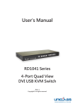
1
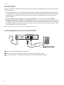
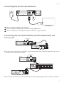
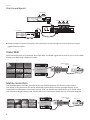
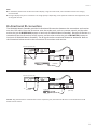
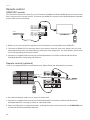
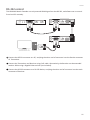
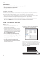
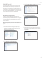
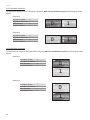
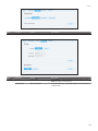
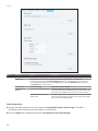
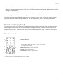
User's Manual
HX120T/R/W
HDMI AV Matrix Extender
&
Video Wall
Version : 1.1
HX120
Introduction................................................................................................................. 3
Features........................................................................................................................ 3
Specification................................................................................................................ 4
Package contents....................................................................................................... 4
Product overview....................................................................................................... 5
Connection................................................................................................................... 6
Connecting the local unit (Transmitter)........................................................... 6
Connecting the remote unit (Receiver)............................................................ 7
Connecting the local (Transmitter) and remote (Receiver) unit ................ 7
Point to point............................................................................................................... 7
Point to multipoint...................................................................................................... 8
Video Wall................................................................................................................ 8
Matrix connection.................................................................................................. 8
Bi-directional IR connection................................................................................ 9
Remote control......................................................................................................10
HDMI CEC remote...................................................................................................... 10
Remote control (optional)....................................................................................... 10
RS-232 control ...................................................................................................... 11
Operation.................................................................................................................... 12
Control manually................................................................................................... 12
Setup from web user interface.......................................................................... 12
IP detection ................................................................................................................ 12
Identify the unit.......................................................................................................... 13
IP address assignment.............................................................................................. 13
Web UI..................................................................................................................... 15
OSD control ............................................................................................................... 25
Remote control (optional).................................................................................. 25
Remote controller...................................................................................................... 25
Basic operation........................................................................................................... 26
Additional options..................................................................................................... 26
HDMI CEC................................................................................................................ 26
Technical support...................................................................................................... 27
FCC / CE Statements................................................................................................. 27
2
HX120
Thanks for purchasing HDMI AV Matrix Extender (Transmitter, Receiver and Video Wall Receiver). With
our highly reliable and quality product, you can enjoy countless benefits by using this KVM Extender.
Introduction
The HDMI AV Matrix Extender comprises three distinct units, the Transmitter, Receiver and Video Wall
Receiver. It is a LAN based KVM Extender system and allowed accessing a computer from a remote
console anywhere on your existing network infrastructure. Keyboard, mouse, USB 2.0 devices, audio and
video can be extended away from your local PC or source by using single Cat5 cable transmission. For
convenience of control, the IR is built-in and the connected AV device can be remote from either end of
connection. In additional, RS232/UART extension is supported as well.
Note: In case of to extend another 100M range, it needs to install the Gigabit Network Switch.
Features
Support direct connection of 100M/330ft with Gigabit Ethernet Switch
2 x USB 2.0 port over IP extension
Support Digital Video resolution of 1920x1200 @60Hz
Bi-directional IR pass-through for added convenience
Complaint to HDMI 1.3 CEC specification
Support 7.1 audio channel
Support A/V Matrix up to 256x256 (HX120T/HX120R Combo)
Support RS232/UART Extension function
Support 8x8 Video Wall (HX120T/HX120W Combo)
3
HX120
Specification
Model No.
Product Description
Console USB Hub Ports
PC USB Port
IR support
Video Input Port
Video Output Port
Audio Input Port
Audio Output Port
RS-232 Extension Support
Ethernet Connectors
Cable media
Power LED
Video LED
Device LED
Operation Temperature
Storage Temperature
Humidity
Safety / Emission
HX120T
HDMI AV Matrix Extender &
Video Wall - Transmitter
Type B Female Yes
HDMI Female
via RJ45
via HDMI
via RJ45
Yes
Yes
CAT5e/ CAT6
1 (Red)
1 (Green)
0 ~ 40°C
-20 ~ 60°C
0~90% RH, Non-Condensing
CE, FCC
HX120R
HDMI AV Matrix Extender Receiver
2 x USB 2.0 Type A Female
HX120W
HDMI AV Matrix Extender &
Video Wall - Receiver
2 x USB 2.0 Type A Female
Yes
via RJ45
HDMI Female
via RJ45
via HDMI
Yes
Yes
CAT5e/ CAT6
1 (Red)
1 (Green)
1 (yellow)
0 ~ 40°C
-20 ~ 60°C
0~90% RH, Non-Condensing
CE, FCC
Yes
via RJ45
HDMI Female
via RJ45
via HDMI
Yes
Yes
CAT5e/ CAT6
1 (Red)
1 (Green)
1 (yellow)
0 ~ 40°C
-20 ~ 60°C
0~90% RH, Non-Condensing
CE, FCC
Package contents
Transmitter Unit x 1
Receiver Unit x 1
Video Wall Unit (optional) x 1
Power Adapter (DC9V) x 3
CD-ROM (Driver & User's Manual) x 1
Remote Control (optional) x 1
IR Remote Control Unit Pack (Include: Wired Transmitter and Wired Receiver, Optional) x 1
4
HX120
Product overview
Transmitter
Front panel
1
Rear panel
2
5
4
6
7
9
10
15
16
17
14
11
12
13
14
11
12
13
14
Receiver
Front panel
1
2
Rear panel
3
4
5
6
7 8
9
10
Video Wall
Front panel
1
No.
1
2
3
2
Rear panel
3
4
Item
Reset
Connect
Devices
5
6
7 8
9
10
Description
Press to re-start the unit.
Press to re-connect the Transmitter/Receiver if the DIP switch has been reset.
■ Press to connect the device which plugged into Receiver's USB port to console.
Note: Please check the Devices indicator (No. 8) after USB device has been plugged in to the
unit. No device will be found if the Device indicator (No. 8) lights off. If it happens, press this
button to light it up and re-connect.
4
5
6
7
8
9
10
11
12
13
14
15
16
17
IR receiver
IR Emitter
DIP switch
Video indicator
Devices indicator
Power indicator
Power jack
RS232 male connector
HDMI Output
USB Type-A connector
RJ45 connector
RS232 female connector
HDMI input
USB Type-B connector
■ Press to update the EDID of connected monitor. To update the EDID, remove the
Receiver's power. Hold the device button and then power on the unit. Release the
Device button when the Power indicator flashes.
Connect to a IR receiver.
Connect to a IR emitter.
4-position dip switch for pairing with Transmitter and Receiver.
Lights when video is transferring.
Lights when the device is connected to console (Devices button is pressed).
Lights when power is on.
Connect to the power adapter.
Connect to RS232 device.
Connect to a display device.
Connect to USB devices.
Connect to Transmitter/Receiver.
Connect to a host PC.
Connect to a video source/PC.
Connect to a host PC.
5
HX120
Connection
Before connecting the HDMI AV Matrix Extender with an Ethernet Hub/Switch, please read the notices
mentioned below
1. When grouping the network of HDMI AV matrix Extender/Video wall, a Gigabit Ethernet Hub/Switch
is necessary due to the requirement of bandwidth. The required bandwidth for each channel may up
to 200mb/sec. To ensure the better quality of transmission, a reputable name brand hub/switch is
recommended.
2. Gigabit Ethernet Switch/HUB with feature of Jumbo Frame is required, other specs like IGMP
Snooping, IGMP Querier, IGMP v2 and IGMP Fast Leave are strongly recommended. If more than one
transmitter connects to the same network segment without support of IGMP Querier by Switch/Hub,
the HDMI AV Matrix Extender may work incorrectly. For more setting details of these functions, refer
to the Hub/Switch's instruction manual.
Note: The diagrams below are examples, the actual applications may vary.
Connecting the local unit (Transmitter)
1
2
3
1
3
or
2
1
Connect the power adapter to a wall outlet.
2
Connect a video source to HDMI input of Transmitter using a HDMI cable.
3
Connect a computer to USB type B connector of Transmitter using a USB cable.
6
HX120
Connecting the remote unit (Receiver)
1
2
3
1
2
1
Connect the power adapter to a wall outlet.
2
Connect a display to HDMI output of Receiver using a HDMI cable.
3
Connect a USB device to USB type A connector of Receiver using a USB cable.
Connecting the local (Transmitter) and remote (Receiver) unit
Point to point
TV
Receiver
USB devices
Transmitter
A/V source or PC
■ To connect the Transmitter and Receiver, simply connect both units using CATx cable directly and the
distance can be extended up to 100m.
USB devices
Receiver
TV
Transmitter
A/V source or PC
■ Alternatively, the Receiver can be extended another 100m using a Gigabit Ethernet hub (not included).
7
HX120
Point to multipoint
USB devices
TV
Receiver Receiver Receiver
Receiver
Transmitter
Gigabit Ethernet Switch
A/V source or PC
■ Except the point to point connection, the Transmitter can be extended to several Receivers using a
gigabit Ethernet switch.
Video Wall
With the combination of Transmitter and Video Wall, the HDMI signal can be sent to one or multi HDMI
display up to 8x8 using a single Cat5 cable.
Gigabit Ethernet
Switch
Receiver
A/V source
PC
Video Wall x 9
Transmitter
or
Matrix connection
The HDMI AV Matrix Extender provides varied and flexible extension for diversity requirements.
The display of A/V sources or PC can be mixed with matrix switch function through the pair of the
Transmitters and Receivers in the same channel. User can extend the matrix switch up to 16x16 works
with a Ethernet Gigabit Switch/Hub. Please refer to the illustrations below for the connection diagram.
Gigabit Ethernet
Switch
A/V source
PC
Receiver x 8
Transmitter
8
HX120
Note:
■ For the better performance of video and matrix display, using the same brand, size and model monitors are strongly
recommended.
■ The lag of displays may occur sometimes. The image quality is depending on the speed of network or the equipments, such
as the grade of hub.
Bi-directional IR connection
The HDMI AV Matrix Extender provides bi-directional IR extension between the transmitter and receiver
over the CATx cable. Place the IR receiver near the sender unit, such as a remote control, and the other
end to the jack of IR RECEIVER (remote or local unit of HDMI AV Matrix Extender). Place the IR Emitter to
somewhere face the IR receiver of A/V source, and the other end to the jack of IR EMITTER (remote or
local unit of HDMI AV Matrix Extender). The IR signal can be transmitted forward or backward. Refer to
the illustration below to outline the connection of transmitter and receiver.
Receiver (remote unit)
IR Receiver
Transmitter
(loacl unit)
IR Emitter
DVD Player
Receiver (remote unit)
TV
IR Emitter
IR Receiver
Transmitter
(loacl unit)
Caution: Plug the IR Receiver and IR Emitter into the respective jacks, otherwise the IR sensor on the IR Receiver and IR
Emitter will be invalid.
9
HX120
Remote control
HDMI CEC remote
CEC (Consumer Electronics Control) is one of features of HDMI that allows HDMI devices to control each
other using only one remote control. To achieve the HDMI CEC remote by the HDMI AV Matrix Extender,
please refer to the notes below.
Extender Receiver/
VideoWall Receiver
Player
Transmitter
1. Make sure the connected AV equipments and TV/monitors are compatible with HDMI CEC.
2. The name of HDMI CEC (for example, Bravia sync control, VieraLink, Kuro Link, Aquos Link, etc.) and
operating settings may vary depending on the brands of AV equipment. For more details, please refer
to the corresponding instruction manual.
3. Connect to a Gigabit Ethernet hub (not included) between Transmitter and Extender Receiver/
VideoWall Receiver if extending the distance.
Remote control (optional)
If CEC is not supported by the connected devices, please follow the steps below to remote.
Transmitter
HDMI cable x 9
Gigabit Ethernet hub
Player
Receiver x 9
1. Set a desired display mode (1 to 1, matrix or video wall).
2. Connect to a Gigabit Ethernet hub (not included) between Transmitter and Extender Receiver/
VideoWall Receiver if setting to matrix or video wall mode.
3. Place the IR Receiver to a desired location, and plug the other end of connector into IR RECEIVER jack
of Extender Receiver/VideoWall Receiver.
10
HX120
RS-232 control
The HDMI AV Matrix Extender not only extends HDMI signal but also RS-232, and allows user to control
from local PC remotely.
2
RS232 device
3
Receiver (remote unit)
1
Transmitter (loacl unit)
1
Connect the RS232 connector to a PC, and plug the other end of connector into the female connector
of Transmitter.
2
Connect the Transmitter and Receiver using Cat5 cable. Alternatively, the Receiver can be extended
another 100m using a Gigabit Ethernet hub (not included).
3
Connect the RS-232 connector to a RS-232 device, and plug the other end of connector into the male
connector of Receiver.
11
HX120
Operation
To operate the HDMI AV Matrix Extender, two ways are provided.
1. Operate by adjusting the DIP manually.
2. Setup from web user interface.
Control manually
With the convenient push button and DIP Switch on the front panel, user can quickly and easily to
operate the HDMI AV Matrix Extender directly. Please follow the steps below to setup.
1. Follow the previous chapter (Connection) to connect all devices according to your desired mode.
2. Adjust the DIP switches of transmitter and receiver/Video to the same positions.
3. Power the transmitter, Extender Receiver/VideoWall Receiver and AV devices/computers to on.
Note: Press the CONNECT button on the front panel of unit once the DIP switch has been adjusted.
Setup from web user interface
IP detection
1. Adjust the DIP switch of Transmitter and
Receiver to the same position.
6. Enter the IP address which detected from
Bonjour Browser into a web browser.
2. Group the Transmitter and Extender Receiver/
VideoWall Receiver units to a network with a
PC. The actual connection may vary depending
on requirements. For more connection details,
refer to the Connection chapter.
3. Turn on the power of all connected devices.
4. Insert the bundled CD/DVD into CD/DVD ROM,
Find and double click the "Bonjour Browser"
from the bundled CD/DVD after completing
the steps above.
5. Click Web Server (HTTP) to detect all the
connected Transmitter and Extender Receiver/
VideoWall Receiver units.
12
Alternatively, remove the Cat5 cable from the
unit you wish to know the IP, and then re-connect
to the unit. The screen will re-detect the input
source and show the IP information before the
image source appears.
HX120
Identify the unit
3. Click Change adapter settings from left side.
The naming rule of these units is based on the
MAC address which labeled on the bottom of
the devices. For example, if the MAC address of
Transmitter is 00:11:AA:CB:00:01, the device will
be named to HX120T-CB0001. T is for Transmitter,
R is for Receiver and W is for Video Wall.
IP address assignment
4. Click Local Area Connection.
If the PC cannot access the Transmitter and
Extender Receiver/VideoWall Receiver using web
UI, please follow the steps below to join the PC
to the network.
Note: The example shown here is using Windows 7. For
other operating systems, please refer to the respective user
guides.
1. Click Control Panel to bring up Adjust your
computer's settings window, and then click
Network and Internet item.
5. Mouse right click Local Area Connection to
bring up a pop-up window, and then select
Properties.
2. Click Network and Sharing Center.
13
HX120
6. Click Internet Protocol Version 4 (TCP/IPv4),
and then click Properties.
7. Click Use the following IP address to specify
an IP address that is on the same subnet as
Transmitter/Extender Receiver/VideoWall
Receiver.
14
HX120
Web UI
■ To configure each unit of HDMI AV Matrix AV Extender, open a browser and type the IP address which
you got from Bonjour Browser. The corresponding web page will appear on the screen as following.
■ Click Apply once the settings have been changed.
Transmitter
Item
System
Sub-item
Version information
Update Firmware
Utilities
Item
Network
Option
Description
Display the information of unit.
Update the firmware. The browser will be reloaded after updating. Please contact the
technical support if you have problem to upload.
Factory Default
Restore to the factory default settings.
Reboot
Restart the system.
Reset EDID
Reset EDID to factory default setting.
Sub-item
IP Setup
Option
DHCP/Static
Device Mode
Matrix/Extender
Description
Select DHCP to obtain IP address automatically or select
Static to assign an IP manually.
Select the operation mode depending on the connection
requirements.
15
HX120
Item
Function
Sub-item
USB over IP
Serial over IP
Option
Description
Enable/disable the sharing of USB peripheral through Ethernet.
Baudrate setting
Setup the baudrate settings.
Baudrate settings
■ This option allows setting the baudrate of Transmitter, Extender Receiver/VideoWall Receiver manually.
Make sure the settings must match with the RS-232 device you have connected. By default, the system
settings are as following:
Baudrate: 115200
Data bits: 8
Parity: None
Stop bits: 1
■ Click the Apply once the baudrate settings have been changed.
Receiver
Item
System
Sub-item
Version information
Update Firmware
Utilities
16
Option
Description
Display the information of unit.
Update the firmware. The browser will be reloaded after updating. Please contact the
technical support if you have problem to upload.
Factory Default
Restore to the factory default settings.
Reboot
Restart the system.
HX120
Item
Channel
Sub-item
Channel Select
Option
Description
Select a desired channel from the Transmitters.
Pairing the Transmitter and Receiver
■ When grouping the network of HDMI AV Matrix Extender/Video Wall using multipoint to multipoint,
the channel selections may be complicated. This option allows user to select the channel more
intuitively. User can click the desired channel on the web oriented user interface directly.
■ Click Apply after selecting the desired channel.
■ The channels may vary, it depends on the number of connected Transmitters.
■ If the option of Save channel select has been ticked, the channel will be saved and based on the
selection of web page, even the settings of DIP switch are different between Transmitter and Receiver.
■ If the option of Save channel select has not been ticked, the channel will be switched to the selection.
Note that this selected channel will not be saved once the power is unplugged. The actual connected
channel is depending on the DIP switch when the power is re-plugged.
■ Reload the channels in the browser once the connection of Transmitter is changed.
Item
Network
Sub-item
IP Setup
Option
DHCP/Static
Device Mode
Matrix/Extender
Description
Select DHCP to obtain IP address automatically or select
Static to assign an IP manually.
Select the operation mode depending on the connection
requirements.
17
HX120
Item
Function
Sub-item
Video over IP
USB over IP
Serial over IP
Miscellaneous
Settings
Option
Description
Enable/disable the copy function from EDID compliant monitors automatically.
Enable/disable the sharing of USB peripheral through Ethernet. To enable this
function, tick the option of Enable USB over IP both on the web pages of receiver and
corresponding transmitter, then click Apply. Next, press the DEVICES button to light up
the DEVICE LED on the receiver.
Baudrate setting
Setup the baudrate settings.
Enable Channel OSD display Enable the display of channel number after the video
connection has been established. The channel number will
be shown on the upper-left of screen for a few seconds.
Turn Off Screen When No
Enable the monitor into standby mode. If there is no video
Video Input
input from transmitter to receiver, the receiver will trigger
the monitor into standby mode.
Baudrate settings
■ This option allows to set the baudrate of Transmitter, Extender Receiver/VideoWall Receiver manually.
Make sure the settings must match with the RS-232 device you have connected. By default, the system
settings are as following:
Baudrate: 115200
Data bits: 8
Parity: None
■ Click the Apply once the baudrate settings have been changed.
18
Stop bits: 1
HX120
Video Wall
Item
System
Sub-item
Version information
Update Firmware
Utilities
Option
Description
Display the information of unit.
Update the firmware. The browser will be reloaded after updating. Please contact the
technical support if you have problem to upload.
Factory Default
Restore to the factory default settings.
Reboot
Restart the system.
19
HX120
Item
Sub-item
Video Wall Bezel and Gap
Compensation
Wall Size and Position
Layout
Apply To "All"
device(s) in the list
Option
Description
Adjust the compensation for bezel between panels.
Setup the display quantities, and specify the positions for each display.
Apply the settings above to specify or all devices in the list. The screens will refresh after
pressing Apply button.
* Show OSD: Enable/disable the display of number on each monitor. To sort the sequence of monitors, please configure the
position of row and column.
0
20
0
1
2
3
HX120
Bezel and Gap Compensation
Visible Height
Outline Height
Outline Width
Visible Width
■ Enter the values to the outline width, visible height, outline height and visible width respectively
according to the bezels of monitors.
■ Click the Apply once the values have been set.
■ Note that the values should be integer.
Wall Size and Position Layout
■ Numbers of Row: The monitor number of row and up to 8.
■ Numbers of Column: The monitor number of column and up to 8.
■ Row Position: Specify the row position of monitor. The row order from top to bottom is 0-7.
■ Column Position: Specify the column position of monitor. The row order from left to right is 0-7.
■ Apply: You can specify the monitor you wish to apply from this drop down menu or apply the settings
to all monitors.
The Video Wall is built by multiple rows and column. The minimum matrix of Video Wall is 1x2. To setup
the Video Wall, please refer to the examples below.
0
1
7
7
21
HX120
1x2 Video Wall (example)
To extend the display on the Video Wall, setup the Wall Size and Position Layout by following the table
below:
Monitor 1
Numbers of Row
Numbers of Column
Row Position
Column Position
1
2
0
0
0
1
1
2
0
1
0
1
Monitor 2
Numbers of Row
Numbers of Column
Row Position
Column Position
2x1 Video Wall (example)
To duplicate the image on the Video Wall, setup the Wall Size and Position Layout by following the table
below:
Monitor 1
Numbers of Row
Numbers of Column
Row Position
Column Position
2
1
0
0
0
1
Monitor 2
Numbers of Row
Numbers of Column
Row Position
Column Position
2
1
1
0
0
1
22
HX120
Item
Channel
Sub-item
Channel Select
Option
Description
Select a desired channel from the Transmitters.
Item
Network
Sub-item
IP Setup
Option
DHCP/Static
Device Mode
Matrix/Extender
Description
Select DHCP to obtain IP address automatically or select
Static to assign an IP manually.
Select the operation mode depending on the connection
requirements.
23
HX120
Item
Function
Sub-item
Video over IP
USB over IP
Serial over IP
Miscellaneous
Settings
Option
Description
Enable/disable the copy function from EDID compliant monitors automatically.
Enable/disable the sharing of USB peripheral through Ethernet. To enable this
function, tick the option of Enable USB over IP both on the web pages of receiver and
corresponding transmitter, then click Apply. Next, press the DEVICES button to light up
the DEVICE LED on the receiver.
Baudrate setting
Setup the baudrate settings.
Enable Channel OSD display Enable the display of channel number after the video
connection has been established. The channel number will
be shown on the upper-left of screen for a few seconds.
Turn Off Screen When No
Enable the monitor into standby mode. If there is no video
Video Input
input from transmitter to receiver, the receiver will trigger
the monitor into standby mode.
EDID configuration
■ To copy the EDID information, tick the option of Copy EDID from this Video Output. The EDID
information will be copied each time power on the Receiver.
■ Click the Apply after ticking/unticking the Copy EDID from this Video Output.
24
HX120
Baudrate settings
■ This option allows to set the baudrate of Transmitter, Extender Receiver/VideoWall Receiver manually.
Make sure the settings must match with the RS-232 device you have connected. By default, the system
settings are as following:
Baudrate: 115200
Data bits: 8
Parity: None
Stop bits: 1
■ Click the Apply once the baudrate settings have been changed. OSD control
Two OSD control are provided, both operations are almost the same. One is using the remote control
(optional), and the other is through HDMI CEC. For more operations, refer to the description below.
Remote control (optional)
The description below is an example for switching between different channels. The operation may vary
depending on actual usage and connection. Before using the function of remote control, refer to the
chapter of Connection - Remote control to set the desired display mode (1 to 1, matrix or video wall).
Remote controller
1
1
2
3
4
5
6
7
8
9
1. Numeric buttons*
2. MENU button
3. Cursor and OK buttons:
Cursor buttons: Move the cursor up, down, right, and left.
OK: Confirm the selection.
0
2
MENU
5
3
4. BACK button: Return to the upper page.
5. CH UP*: Tunes up one channel.
OK
BACK
4
CH UP
6. CH DOWN*: Tunes down one channel.
CH DOWN
6
* These functions are available depending on the models.
25
HX120
Basic operation
1. Press Menu button to bring up the device ID.
Step2
HX120W-D0001C
Step3
HX120W-D0001C
Select Channel
About
Step4
Select Channel
Scan node
HX120T-C80006
HX120T-C80007
[HX120T-C80008]
HX120T-C80009
2. The device ID will appear on the screen. To specify the desired device, press Left or Right button. Once
the device has been confirmed, press OK to bring up more options.
3. Select Select Channel, and then press OK.
4. The available sources will be listed on the screen. Press Up or Down button to select the desired
source, and then press OK.
5. The screen will display to the new source you have selected.
Additional options
■ Select Scan node to refresh if more devices have been connected.
■ Select About to show the firmware version.
HDMI CEC
Except the remote control (optional), remote the device through HDMI CEC is supported as well. The
operation is similar with the remote control described above. Note that the definition of Menu button
on the remote control and name of HDMI CEC may vary (for example, Bravia sync control, VieraLink,
Kuro Link, Aquos Link, etc.). For more details, please refer to the corresponding instruction manual or
manufacturer.
26
HX120
Technical support
Please contact with your local distributor for more information or technical support.
FCC / CE Statements
FCC Statement : This equipment has been tested and found to comply with the regulations for a Class
B digital device, pursuant to Part 15 of the FCC Rules. These limits are designed to provide reasonable
protection against harmful interference when the equipment is operated in a commercial environment.
This equipment generates, uses, and can radiate radio frequency energy and, if not installed and used in
accordance with this User Guide, may cause harmful interference to radio communications. Operation of
this equipment in a residential area is likely to cause harmful interference in which case, the user will be
required to correct the interference at his/her own expense.
CE Statement : This is a Class B product in a domestic environment, this product may cause radio
interference, in which case the user may be required to take adequate measures.
RoHS Compliant
27
http://www.uniclass.com.tw/