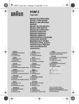
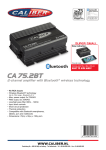
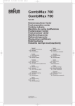
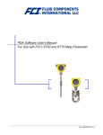
1
Rozna ulica 20, 6230 Postojna, Slovenia
e-mail: [email protected]; www.rec-bms.com
LCD – TFT 2.8” for REC BMS
User Manual
Features:
-
robust and small design
touch screen display
low power consumption
main parameters view tab + 4 sub-menu tab + settings-menu tab
portrait/landscape view
automatic/manual backlight setting
hibernate timer
reverse polarity supply voltage protection
under and over-voltage protection
aluminum enclosure
one-year warranty
General description of the LCD touch display for REC BMS
Battery management system (BMS) is a device that monitors and controls each cell in the battery pack by
measuring its parameters. Its job is to maintain the battery pack in the safe operating range, provided by the
manufacturer. 2.8” LCD – TFT screen shows all the parameters of the electric/hybrid vehicle equipped with REC
BMS.
LCD –TFT may be connected to the independent BMS unit (4-15 cells) or Master BMS unit – up to 225 cells. User
can monitor the parameters in real-time and diagnose the potential errors in the system. LCD – TFT requires its
own power supply (10-16 V). Reverse polarity, under-voltage and over-voltage protection is integrated in the
power management circuit of the LCD –TFT. An ambient light sensor is added to automatically adapt backlight of
the LCD and decrease power consumption. LCD – TFT is equipped with professional protection foil with spacer
dots to cancel the light interference on the display.
User can define the communication cable length from 0.3 m to 6 m and choose between back or side cable exit.
1
LCD – TFT 2.8” USER MANUAL
Table 1: General parameter table.
Parameter
Supply voltage
Supply current (10.0 V)
Low voltage disconnect
Enclosure dimensions (w × l × h)
Weight (6 m communication cable)
Value
10 - 16
< 43
9.8
104 x 69 x 16
410
Unit
V
mA
V
mm
g
System overview:
Figure 1: LCD –TFT overview.
Table 2: LCD-TFT tab description.
Icon
Tab
Description
Main parameters
First tab shows main parameters of the battery powered system.
Cell’s voltage
Cell’s impedance
Cell’s temperature
Second tab shows each cell’s voltage. User can sweep through
slave units if present.
Third tab shows each cell’s DC impedance. User can sweep
through slave units if present.
Forth tab shows battery pack temperature. User can sweep
through slave units if present.
BMS temperature
Fifth tab shows each BMS temperature (passive balancing).
LCD –TFT settings
Sixth display serves for LCD –TFT settings.
2
www.rec-bms.com
LCD – TFT 2.8” USER MANUAL
Figure 2: First tab - main parameters.
Table 3: First tab - main parameters overview.
Window
SOC
BAT. VOLT [V]
CURRENT [A]
TIME TO FULL/EMPTY
CMAX [V]
CMIN [V]
TEMP [°C]
POWER [kW]
SOH [%]
Description
State of charge of the battery pack
Battery pack voltage
Battery pack current (positive when charging)
Approximate time when the battery pack is full
(charging) or empty (discharging)
Maximum cell’s voltage
Minimal cell’s voltage
Maximal temperature
Battery pack power
State of health
Figure 3: Second tab – cell’s voltages.
3
www.rec-bms.com
LCD – TFT 2.8” USER MANUAL
Figure 4: Third tab – cell’s DC impedance.
Figure 5: Fourth tab – cell’s temperatures.
Figure 6: Fifth tab – BMS temperatures.
4
www.rec-bms.com
LCD – TFT 2.8” USER MANUAL
Figure 7: LCD –TFT settings.
Table 4: LCD –TFT settings buttons description.
Icon
SOC
BAT. VOLT
CURRENT
TIME TO…
CMAX
CMIN
TEMP
POWER
SOH
DISP. OFF
BCK. LIGHT
Rotate
DIAGNOSTIC
Description
Show/Hide SOC from the main parameters’ tab
Show/Hide battery pack voltage from the main parameters’ tab
Show/Hide battery pack current from the main parameters’ tab
Show/Hide Time to full/empty from the main parameters’ tab
Show/Hide CMAX from the main parameters’ tab
Show/Hide CMIN from the main parameters’ tab
Show/Hide highest temperature from the main parameters’ tab
Show/Hide power from the main parameters’ tab
Show/Hide SOH from the main parameters’ tab
Selects or turns-off backlight sleep mode timer.
Selects automatic or manual backlight settings.
Rotates screen Portrait/Landscape.
Describes the error in the system.
RS-485 Communication connector
Figure 8: LCD –TFT RS-485 DB9 female connector front view.
Table 5: RS-485 DB-9 connections.
Pin
1
2
3
4
5
6
7
8
9
Designator
AGND
B
A
+3.4 V
-
5
www.rec-bms.com
LCD – TFT 2.8” USER MANUAL
LCD –TFT is providing 3.4 V for power supply of the galvanically isolated RS-485 driver.
Galvanic isolation up to 2.5 kV is provided. No additional termination resistors are required.
2.8” LCD-TFT connection instructions
Figure 9: LCD –TFT connection to REC BMS 9R.
Figure 10: LCD –TFT connection to REC BMS Master Unit 9M.
6
www.rec-bms.com