1
CodeVisionAVR
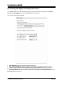
5.8 Setting the Analog to Digital Converter
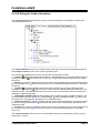
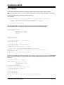
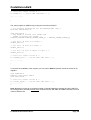
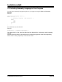
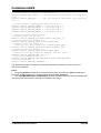
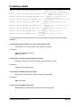
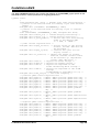
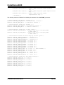
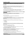
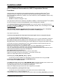
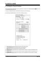
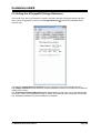
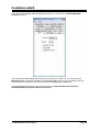
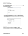
Some AVR chips contain an Analog to Digital Converter (ADC).
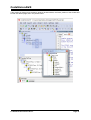
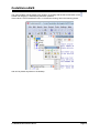
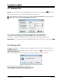
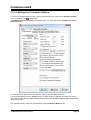
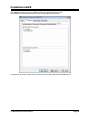
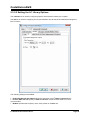
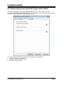
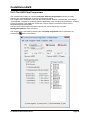
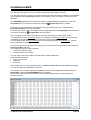
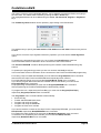
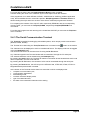
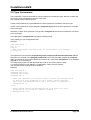
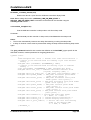
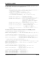
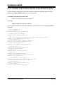
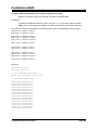
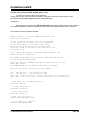
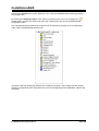
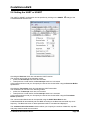
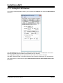
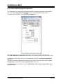
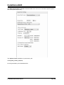
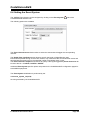
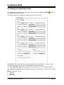
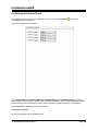
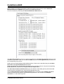
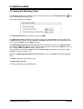
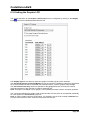
The ADC configuration can be specified by clicking on the Analog to Digital Converter
the CodeWizardAVR selection tree.
node of
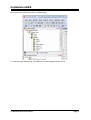
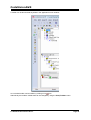
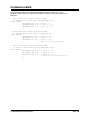
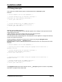
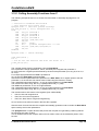
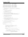
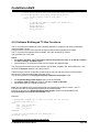
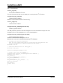
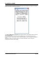
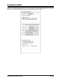
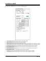
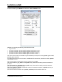
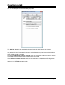
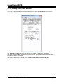
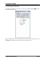
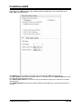
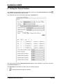
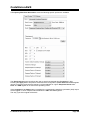
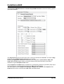
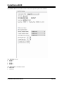
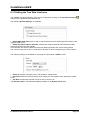
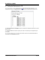
Checking the ADC Enabled check box enables the on-chip ADC.
On some AVR devices only the 8 most significant bits of the AD conversion result can be used. This
feature is enabled by checking the Use 8 bits check box.
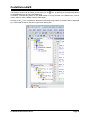
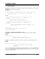
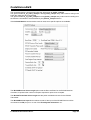
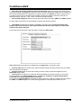
The ADC may be operated in bipolar mode if the Bipolar Input check box is checked.
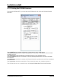
Some AVR devices allow the ADC to use a high speed conversion mode, but with lower precision.
This feature is enabled by checking the High Speed check box, if present.
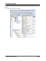
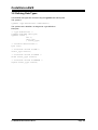
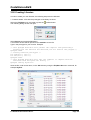
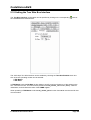
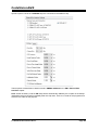
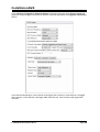
If the ADC has an internal reference voltage source, than it can be selected using the Volt. Ref. list
box or activated by checking the ADC Bandgap check box.
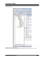
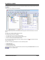
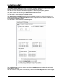
The ADC clock frequency can be selected using the Clock list box.
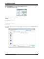
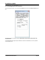
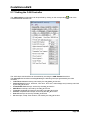
If you want to generate interrupts when the ADC finishes the conversion, then you must check the
Interrupt check box.
© 1998-2012 HP InfoTech S.R.L.
Page 408