1
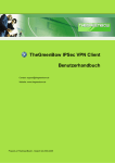
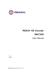
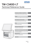
Reach Bee 8 User Manual Documentversion Released date V1.0 2013-10 i Shenzhen Reach IT Co., Ltd provides full technical supports for the customers. If you have any inquiries, please contact the local Reach office or directly contact the headquarters of the company. SZ REACH TECH CO., LTD. Address: Postal code: Website: Tel.: Customer service hotline: Customer service fax: Unit 601, Block B, Kingdee Software Park, No. 2, Technology Southern No. 12 Rd. South District of Hi-Tech Industrial Park, Nanshan District, Shenzhen 518057 http://www.szreach.com +86 755 86073600 +86 4007160868 +86 755 86073689 Copyright© SZ REACH TECH CO., LTD. 2013. All rights reserved. Any part of this document, including the text, image and graph, is the property of SZ REACH TECH CO., LTD. No part of this document shall be copied in any means without the prior written consent of SZ REACH TECH CO., LTD. Reach reserves the right to revise this document without any prior notice. Reach provides warranty of limited liabilities for the software and hardware product. For any loss of the users caused by the design defect of the software and hardware, Reach will compensate the user with the amount up to the price specified in the product purchase contract. Trademark Statement Reach, REACH, , Reach Software, Beyonsys™ and Powolive™ are the trademarks of SZ REACH TECH CO., LTD. Windows, Windows 95, Windows 98, Windows NT, Windows 2000, Windows 2003, Windows XP and Windows 7 are the trademarks of Microsoft. Other trademarks are the properties of their respective owners. Note This user manual is compiled to ensure easy installation and configuratione of the product. Please read this manual carefully before using the product, so that you can make best use of all its functions. This manual is subject to update from time to time without prior notice. If you come across any problem that cannot be solved according to the manual, please contact our company for solutions. Thank you. ii REACHBee 8 CL360 User Manual Contents 1. OVERVIEW ............................................................................................................... 1 1.1 PRODUCT FUNCTIONS .......................................................................................................... 1 1.2 PRODUCT ADVANTAGES ....................................................................................................... 2 2. BEE 8 OPERATION GUIDE ..................................................................................... 2 2.1 FRONT PANEL BUTTON DESCRIPTION ................................................................................. 2 2.2 BUTTON OPERATION DESCRIPTION ..................................................................................... 4 2.3 REAR PANEL PORTS DESCRIPTION...................................................................................... 6 3. BEE 8 CONFIGURATION ........................................................................................ 7 3.1 BEE 8 W EB INTERFACE LOGIN ............................................................................................. 7 3.2 FILE MANAGEMENT ............................................................................................................... 8 3.3 PARAMETER SETTING ......................................................................................................... 10 3.3.1 Video Setting ................................................................................................................. 11 3.3.2 Video Encoding ............................................................................................................. 13 3.3.3 Audio Setting ................................................................................................................. 13 3.3.4 Streams .......................................................................................................................... 14 3.3.5 Camera Control ............................................................................................................ 17 3.3.6 Image Correcting .......................................................................................................... 19 3.3.7 Title /Logo ...................................................................................................................... 20 3.4 SYSTEM CONFIGURATION................................................................................................... 21 3.4.1 Network .......................................................................................................................... 21 3.4.2 User ................................................................................................................................ 21 3.4.3 Device Name ................................................................................................................. 22 3.4.4 FTP Setting .................................................................................................................... 23 3.4.5 System Upgrade ........................................................................................................... 24 3.4.6 USB Function ................................................................................................................ 25 3.5 SYSTEM INFORMATION ....................................................................................................... 26 4. PC MANAGEMENT PLATFORM ........................................................................... 26 4.1 INSTALLING THE MANAGEMENT PLATFORM ....................................................................... 26 All Rights Reserved © SZ REACH TECH CO., LTD. iii REACHBee 8 CL360 User Manual 4.2 OPENING THE MANAGEMENT PLATFORM........................................................................... 26 4.3 ADDING A DEVICE ............................................................................................................... 26 5. PC MANAGEMENT PLATFORM INTERFACE ..................................................... 28 5.1 TOOL BAR ........................................................................................................................... 28 5.2 DEVICE LIST BAR ................................................................................................................ 29 5.3 VIDEO DISPLAY AREA ......................................................................................................... 30 5.4 OPERATION AREA ............................................................................................................... 31 5.4.1 Camera Management .................................................................................................. 31 5.4.2 Picture Adjustment ....................................................................................................... 33 5.4.3 File Management .......................................................................................................... 35 5.4.4 Parameter Setting......................................................................................................... 36 5.4.5 System Management ................................................................................................... 37 6. IPAD CONTROL TERMINAL ................................................................................. 39 6.1 DOWNLOAD AND INSTALLATION .......................................................................................... 39 6.2 LOGIN .................................................................................................................................. 39 6.3 PAGE DESCRIPTION ............................................................................................................ 42 6.4 OPERATION GUIDE.............................................................................................................. 42 6.4.1 Quitting the iPad Control Terminal ............................................................................. 42 6.4.2 Setting the Picture Layout ........................................................................................... 42 6.4.3 Camera Control ............................................................................................................ 43 6.4.4 Recording Control......................................................................................................... 44 6.5 REMEMBERING THE IP ADDRESS AUTOMATICALLY ........................................................... 45 7. MEDIA CENTER (LITE) OPERATION GUIDE ...................................................... 47 7.1 SYSTEM LOGIN ................................................................................................................... 47 7.2 SOFTWARE PLUG-IN ........................................................................................................... 48 7.2.1 Installing a Video Player Plug-in................................................................................. 49 7.2.2 Installing a File Decompression Plug-in .................................................................... 49 8. FRONT-END PAGE OPERATION .......................................................................... 49 8.1 CHECKING A VIDEO FILE ..................................................................................................... 49 8.2 DOWNLOADING A VIDEO FILE ............................................................................................. 49 9. BACK-END PAGE OPERATION ........................................................................... 50 9.1 ACCESSING THE BACK-END PAGE ..................................................................................... 50 9.2 SYSTEM INFORMATION MANAGEMENT ............................................................................... 51 9.2.1 Operation ....................................................................................................................... 51 9.2.2 System Information ...................................................................................................... 55 9.2.3 Settings .......................................................................................................................... 55 All Rights Reserved © SZ REACH TECH CO., LTD. iv REACHBee 8 CL360 User Manual 9.2.4 9.3 System log ..................................................................................................................... 62 ROOM MANAGEMENT ......................................................................................................... 63 9.3.1 Room Management...................................................................................................... 63 9.3.2 Schedule ........................................................................................................................ 65 9.4 USER & AUTHORIZATION MANAGEMENT............................................................................ 67 9.4.1 User Management ........................................................................................................ 68 9.4.2 User Group Management ............................................................................................ 69 9.4.3 LDAP Management ...................................................................................................... 75 9.5 FILE MANAGEMENT ............................................................................................................. 75 9.5.1 File Classification.......................................................................................................... 75 9.5.2 File Maintenance .......................................................................................................... 80 All Rights Reserved © SZ REACH TECH CO., LTD. v REACHBee 8 CL360 User Manual 1. Overview 1.1 Product Functions Reach Bee 8 is a high performance recording and streaming product developed by SZ REACH TECH CO., LTD. Based on the latest DaVinci 168 video processing chip, Bee 8 is integrated with different input and output interfaces for HD video, audio, VGA, and USB signals, allowing it to automatically identify various signal source combinations, and generate general MP4 video files. With these configurations, Reach Bee 8 can control multiple devices such as the PC and tablet concurrently, and provide Android and iOS platforms that allow users to share mobile terminal resources in the integrated media center (lite). Figure 1-1 shows the appearance of a Bee 8 product. Figure 1-1 Bee 8 can be connected to and work together with a Web manage interface, a management platform, an iPad control terminal, and a media center (lite). Figure 1-2 shows the networking diagram of a Reach Bee 8 product. Figure 1-2 All Rights Reserved © SZ REACH TECH CO., LTD. 1 REACHBee 8 CL360 User Manual The Web management interface can be used to: Control and manage Bee 8 remotely, and set Bee 8 system parameters. The PC management platform can be used to: Monitor the status of a collecting device (Bee 8) that is connected to the PC management platform through the IP network, and remotely control cameras in a specific meeting room. The iPad control terminal can be used to: Monitor the status of a collecting device (Bee 8) that is connected to the iPad through the IP network, and remotely control cameras in a specific meeting room. The iPad control terminal is dedicated to the iPad tablet. Compared with the PC management platform, the iPad control terminal is easy to carry and simple to operate. The media center (lite) is used to: Exchange information with users and connect the collecting device (Bee 8) through the IP network to set parameters and manage recording tasks on Bee 8.Allow the guest user to log in to the Web page to view the live image of a meeting room or play a VOD file according to their authorizations. Allow the administrator user to set parameters, assign user authorizations, and release video files on the collecting device (Bee 8). 1.2 Product Advantages Supporting the live recording, live streaming, and VOD playing of HD multi-media signals (in compliance with the media center) Generating MP4 video files Supporting the high speed download and direct recording to the USB device. Controlling and managing the PC and iPad concurrently. Providing the Android and iOS platforms to release video resources (in compliance with the media center) Supporting standard Real Time Streaming Protocol (RTSP) streams 2. Bee 8 Operation Guide 2.1 Front Panel Button Description All Rights Reserved © SZ REACH TECH CO., LTD. 2 REACHBee 8 CL360 User Manual 1 2 3 4 5 6 7 8 9 12 11 10 13 Figure 2-1 Table 2-1 Front panel button description No. Name Description Displays different status information about Bee 8. For example, 1 LCD screen during the starting process of Bee 8, Starting is displayed on the screen. After the startup, information such as the system version, IP address, subnet mask, and network gateway is displayed on the LCD screen in scrolling mode. Displays the sound volume dynamically. 2 Volume The higher the volume bar, the louder the sound; the shorter the volume bar, the smaller the sound. Displays the status of Bee 8. Indicators 3 to 5 specify three different signal sources respectively. 3-6 Status indicator The indicator is on when signals are input; the indicator is off when no signal is input. Indicator 6 specifies the operation status of Bee 8. When Bee 8 operates normally, indicator 6 blinks; when Bee 8 becomes faulty, indicator 6 goes off. Starts a video recording task. The button is light-off by default. If there is no recording task on Bee 7 REC 8 or a running recording task is paused, you can press this button to start recording. The button lights on after being pressed. Information about the running recording task will be displayed on the LCD screen in scrolling mode. Pauses a video recording or VOD playing task. The button is light-off by default. 8 PAUSE If there is a running recording task on Bee 8, you can press this button to pause the task. The PAUSE button lights on after being pressed, and the REC button lights off at the same time. To resume the recording task, press the REC button again. All Rights Reserved © SZ REACH TECH CO., LTD. 3 REACHBee 8 CL360 User Manual No. Name Description If there is a VOD file playing on Bee 8, you can press this button to pause the video playing. The PAUSE button lights on after being pressed. Stops a video recording or VOD playing task. The button is light-off by default. If there is a running recording task on Bee 8, you can press this button to stop the recording task. The button lights on and then off 9 STOP after being pressed. Default information is displayed on the LCD screen in scrolling mode. If there is a VOD file is playing on Bee 8, you can press this button to stop the video playing. The button lights on and then off after being pressed. The live streaming page is displayed on the LCD screen. 10 PLAY Plays a VOD file. You can press this button to open the play (VOD) file list. The button lights on after being pressed. Downloads a file. Connect the USB disk and press this button to 11 Down display the playback file list. The button lights on after being pressed. Exports video files in the hard disk to a USB mobile storage device (in high bit rate). 12 USB Video files being recorded can be automatically saved to the USB mobile storage device in real time. The USB port supports mobile storage devices of USB disk and USB hard drive (in EXT3, NTFS, or FAT32 format). Selects a file in the Playback (VOD) mode and fast forwards/rewinds the playback (VOD) file. Pressing the knob 13 Knob confirms the video playing action. Resumes the playing of a paused video file. Selects a file in download mode. Pressing the knob confirms the file downloading action. 2.2 Button Operation Description Video Recording Recording: Press REC to start recording, and the button lights on after being pressed. The LCD screen displays information about the recording file in scrolling mode. All Rights Reserved © SZ REACH TECH CO., LTD. 4 REACHBee 8 CL360 User Manual Pause: When Bee 8 is in the recording state, press Pause to suspend the recording task. The Pause button is solid on and the REC button lights off. Stop: When Bee 8 is in the recording or pause state, press STOP to stop recording. After pressing the STOP button, the button lights on and then off, and at the same time, the REC or PAUSE button lights off. The LCD screen displays the boot information about Bee 8. Video Playing When Bee 8 is not in the video recording state, press PLAY to display the file playback menu. The operation process is as follows: 1. Press PLAY to display the file list on the LCD screen. 2. Rotate the Knob in clockwise or counterclockwise direction to select the file to be played. 3. Press the Knob to play the selected file. Information about the file being played is displayed on the LCD screen. 4. During video playing, rotate the Knob in clockwise direction to fast forward the video file and in counterclockwise direction to rewind the video file. 5. When the video is fast forwarding or rewinding, press the Knob to continue the video playing. Notice: If you press PLAY during the video playing, the boot information (including information about Bee 8) will be displayed again the LCD screen, without interrupting the video playing. If you press PLAY again, information about the video being played will be displayed on the LCD screen. You can press PAUSE or STOP to pause or stop the video playing. USB File Download Note: 1. When a USB disk or USB mobile hard disk is connected to the USB port, Bee 8 will check the available space of the USB disk or USB mobile hard disk. If the available space is less than 1G, the USB character blinks on the LCD screen, indicating that no video files can be downloaded to the USB disk or USB mobile hard disk. 2. In the scenario where video files are downloaded or directly recorded to the USB disk or USB mobile hard disk, and the available space of the USB disk or USB mobile hard All Rights Reserved © SZ REACH TECH CO., LTD. 5 REACHBee 8 CL360 User Manual disk is less than 50M, the system stops the download or direct recording process and displays the prompt information on the LCD screen. 3. To download files, you need to enable the USB download function on the Web page. For details, see 0 USB Function. USB Download In the scenario where no video file is recorded on Bee 8: 1. When a USB disk or USB mobile hard disk is connected to the USB port, Bee 8 will check the available space of the USB disk or USB mobile hard disk. 2. Press DOWN and the button lights on. The LCD screen displays the file name list. 3. Rotate the Knob in clockwise or counterclockwise direction to select the file to be downloaded. The LCD screen displays the file download progress. 4. After the download, the DOWN button lights off. Direct Recording After the USB disk or USB mobile hard disk is connected to the USB port, video file recorded on Bee 8 will be saved automatically to the USB disk or USB mobile hard disk in real time. 2.3 Rear Panel Ports Description 1 2 3 4 6 7 8 9 10 11 5 12 14 15 16 13 Figure 2-2 Table 2-2 Rear panel ports description No. 1 Name Power switch No. 9 Name R232/RS485/RS422 control interface All Rights Reserved © SZ REACH TECH CO., LTD. 6 REACHBee 8 CL360 User Manual No. 2 Name Power port (PWR) No. Name 10 3.5mm stereo input interface (LINE IN) 3 DVI-I input interface 1 (DVI IN 1) 11 Mono RCA audio input interface (MIC IN) 4 DVI-I input interface 2 (DVI IN 2) 12 Phoenix microphone/stereo input interface 5 DVI-I input interface 3 (DVI IN 3) 13 RCA stereo output interface (left channel) 6 Analog VGA loop output (VGA LOOP) 14 RCA stereo output interface (right channel) 7 VGA video output interface (VGA OUT) 15 Reset button (RESET) 8 Serial port switch 16 LAN interface (LAN) 3. Bee 8 Configuration Bee 8 Web interface is used in conjunction with Bee 8. You can log in to the Web page to remotely set parameters for Bee 8. 3.1 Bee 8 Web interface Login Open the IE browser (IE8 or higher is required), enter the IP address of Bee 8 in the address bar, and press Enter. The Bee8 Web login interface is displayed as shown in Figure 3-1. All Rights Reserved © SZ REACH TECH CO., LTD. 7 REACHBee 8 CL360 User Manual Figure 3-1 Enter the username and password (both of them are admin by default), and click Log in. The Bee 8 Web interface is displayed as shown in Figure 3-2. By default, the System info page is displayed, allowing you to check the series number, model, and version of Bee 8. Figure 3-2 3.2 File Management Click Files to display the file management page as shown in Figure 3-3. All Rights Reserved © SZ REACH TECH CO., LTD. 8 REACHBee 8 CL360 User Manual Figure 3-3 Searching a file When there are too many files in the file list, you can enter the keyword in File name and click to locate the file wanted. Renaming a file Click Rename in the Operation column of a file. As shown in Figure 3-4, the file name is marked in a red box and the cursor appears so that you can rename the file as needed. Figure 3-4 Deleting a file 1. If you click Delete in the Operation column of a file, a dialog box shown in Figure 3-5 is prompted to confirm the deletion action. All Rights Reserved © SZ REACH TECH CO., LTD. 9 REACHBee 8 CL360 User Manual Figure 3-5 2. Click Confirm to delete the file and a dialog box indicating that the file has been deleted will be prompted. 3. Click Yes to complete the deletion operation. Alternatively, you can take no actions and just wait the system to automatically close the prompt page in 3 seconds. Downloading a file If you click Download in the Operation column of a file, a dialog box is prompted, as shown in Figure 3-6. Follow the prompts to download a file as needed. Figure 3-6 3.3 Parameter Setting Click Settings to display the parameter setting page. By default, the Video Setting tab is displayed as shown in Figure 3-7. The Settings page consists of seven tabs, namely, Video Setting, Video Encoding, Audio Setting, Streams, Camera Control, Image Correcting, and Title/Logo. All Rights Reserved © SZ REACH TECH CO., LTD. 10 REACHBee 8 CL360 User Manual Figure 3-7 3.3.1 Video Setting Video settings consist of four parts: Video Output, Video Input, Video Layout, and Full Screen. Video Output Output Resolution specifies the resolution of video signals output from the VGA video output interface. Video Input After Bee 8 is connected to input video signals from a certain interface, you need to determine the signal format by choosing HD or SD in the Web interface. For example, if DVI IN 1 on the rear panel is connected to input SD signals and DVI IN 2 is connected to input HD signals, ensure that the corresponding signal standards (SD or HD) need to be selected in Video Input. Capture Capture indicates whether to output video images. If ticked off, the corresponding video images will be output; if not, no video image will be output. Video Layout All Rights Reserved © SZ REACH TECH CO., LTD. 11 REACHBee 8 CL360 User Manual Video layout specifies the setting of the picture layout on the screen. The video layout mode varies with the number of picture input channels. There are 6 layout modes for 2-channel pictures, as shown in Figure 3-8. Figure 3-8 There are 2 layout modes for 3-channel pictures, as shown in Figure 3-8. Figure 3-9 Full Screen Full Screen displays single-channel pictures in full-screen mode. The process for configuring Video Setting is as follows: 1. Click the drop-down list of Output Resolution to choose the corresponding output resolution, as shown in Figure 3-10. All Rights Reserved © SZ REACH TECH CO., LTD. 12 REACHBee 8 CL360 User Manual Figure 3-10 2. Choose the respective signal standard for Input 1 and Input 2 according to the interface connection type. 3. Choose the number of channels for signal capturing in Capture as needed. 4. Choose the picture layout mode in Video Layout as needed. 5. Click Save and a dialog box prompts indicating that the setting has been saved. 6. Click Confirm to complete the configuration. To switch to the full screen, click Switch. 3.3.2 Video Encoding Click Video Encoding to open the parameter setting page, as shown in Figure 3-11. Select the bit rate according to the actual bandwidth. Figure 3-11 1. Select a value in Bit rate. 2. Select a value in Resolution. 3. Click Save to complete the configuration. 3.3.3 Audio Setting Click Audio Encoding to open the parameter setting page, as shown in Figure 3-12. All Rights Reserved © SZ REACH TECH CO., LTD. 13 REACHBee 8 CL360 User Manual Figure 3-12 After Bee 8 establishes the connection with an audio input device, the audio input device can work properly only after LINE IN or MIC IN is ticked off in the Web interface according to the interface connection type at the rear panel of Bee 8. Note: To ensure the recording quality, do not tick off the interface having no input signals. 1. Tick off LINE IN or/and MIC IN according to the interface connection type. 2. Click Save to complete the configuration. 3.3.4 Streams Click Streams to open the parameter setting page, as shown in Figure 3-13. Figure 3-13 Status specifies the file-receiving status of a third-party video player. The value can be Active, Stop, and Delete (indicating that the playing address is deleted). Deleting a playing address 1. Click the drop-down list in Status and select Delete. 2. Click Setting and a dialog box is prompted, as shown in Figure 3-14. All Rights Reserved © SZ REACH TECH CO., LTD. 14 REACHBee 8 CL360 User Manual Figure 3-14 3. Click Confirm to delete the playing address. The Streams page after the playing address is deleted is shown in Figure 3-15. Figure 3-15 Adding a playing address A deleted playing address can be added again. 1. Click Add to display a dialog box, where you can specify detailed information of the playing address, as shown in Figure 3-16. All Rights Reserved © SZ REACH TECH CO., LTD. 15 REACHBee 8 CL360 User Manual Figure 3-16 2. Click Confirm and a dialog box is prompted, as shown in Figure 3-17. Figure 3-17 3. Click Yes to complete the adding operation. Detailed setting Permission setting: enables or disables the permission authentication function as needed. If Enable is selected, you can only view live videos using the playing address after entering the username and password (which are both guest by default). If Disable is selected, you can directly view live videos without entering the username and password. The process for configuring Detailed Setting is as follows: 1. Click Detailed Setting to open the detailed setting page, as shown in Figure 3-18. All Rights Reserved © SZ REACH TECH CO., LTD. 16 REACHBee 8 CL360 User Manual Figure 3-18 2. Choose Enable in Permission setting as needed. 3. Click Confirm and a dialog box is prompted, as shown in Figure 3-19. Figure 3-19 4. Click Confirm. 5. Click Refresh and you will find that the value of Permission Setting changes from Disable to Enable. 3.3.5 Camera Control Uploading a camera control protocol Click Camera Control to open the parameter setting page, as shown in Figure 3-20. All Rights Reserved © SZ REACH TECH CO., LTD. 17 REACHBee 8 CL360 User Manual Figure 3-20 If there is no suitable camera control protocol for the existing camera, you need to upload an appropriate one. Note: Changing the input setting will lead to systemreboot. You are recommended to stop recording first. 1. Click to select a camera control protocol file (in .ini format) from the local directory. 2. Click Open (O) 3. Click Upload. 4. Click Save. Deleting a protocol 1. Click the drop-down list in PTZ protocol to select a protocol file. 2. Click Delete and a dialog box is prompted. 3. Click Confirm to complete the setting. Setting the address bits of a camera Set the address bits according to the actual location of the camera. The PC management platform can remotely control the PTZ only when the camera address set in the Web interface is identical with the actual camera location. Select the address bits for corresponding cameras in Video 1, Video 2, and Video 3. 2. Click Save and a dialog box is prompted, as shown in Figure 3-21. All Rights Reserved © SZ REACH TECH CO., LTD. 18 REACHBee 8 CL360 User Manual Figure 3-21 3. Click Confirm to complete the setting. 3.3.6 Image Correcting Click Image Correcting to open the parameter setting page, as shown in Figure 3-22. Image Correcting takes effect only on analog signals, not digital signals. Figure 3-22 Video input: controls the moving direction of a specific video image (Input 1, Input 2, or Input 3). Speed setting: Options Mid and High control the moving speed of the video image. The higher the speed level, the faster the direction moving. The option Low modifies the color cast of the image. Picture position: When Speed setting is set to Mid or High, click , , , and to control the moving direction of the video image. When Speed setting is set to Low, click , , , and to modify the color cast of the video image. All Rights Reserved © SZ REACH TECH CO., LTD. 19 REACHBee 8 CL360 User Manual 3.3.7 Title /Logo Click Title/Logo to open the parameter setting page, as shown in Figure 3-23. Figure 3-23 Title setting 1. Click the drop-down list of Position to select the position of the title text in the video image. This parameter has three values, Top left, Top right, and None. None indicates that no title is present. 2. Enter the title text to be displayed in Title contents. 3. Tick off Display time to display the system time of Bee 8 in the video image. 4. Click Save and a dialog box is prompted. 5. Click Confirm to complete the setting. Logo setting Note: The logo image file is in .png format, with its size smaller than 192 x 64. 1. Click the drop-down list of Position to select the logo position in the video image. This parameter has five values, Top left, Top right, Bottom left, Bottom right, and None. None indicates that no logo is present. 2. Click 3. Click Open (O) after a file is selected. 4. Click Confirm and a dialog box is prompted. 5. Click Confirm to complete the setting. to select a logo image file from the local directory. All Rights Reserved © SZ REACH TECH CO., LTD. 20 REACHBee 8 CL360 User Manual 3.4 System Configuration Click Administration to display the system configuration page. By default, the Network tab is displayed as shown in Figure 3-24. The Administration page consists of six tabs, namely, Network, User, Device Name, FTP Setting, Sys Upgrade, and USB Function. Figure 3-24 3.4.1 Network You can obtain the IP address of Bee 8 automatically by enabling Dynamic Host Configuration Protocol (DHCP). Alternatively, you can enter the IP address of Bee 8 manually. 1. Tick off Enable in DHCP to obtain the IP address of Bee 8 automatically. 2. If Enable is not ticked off, you can input the IP address information of Bee 8 manually in IP address, Mask, and Gateway. 3.4.2 User Click User to open the parameter setting page, as shown in Figure 3-25. All Rights Reserved © SZ REACH TECH CO., LTD. 21 REACHBee 8 CL360 User Manual Figure 3-25 Changing the system administrator password The system administrator refers to the user authorized to log in to the Web interface. Note: After changing the system administrator password, you need to change the password for connecting the management platform and media center accordingly. 1. Enter the original password in Old password (the default password is admin). 2. Enter the new password in New password. 3. Re-enter the new password in Password confirm. 4. Click Save in the System Admin part to complete the setting. Changing the guest user password The guest user refers to the user authenticated to receive Real Time Streaming Protocol (RTSP) streams or the ordinary user logging to the iPad control terminal. 1. Enter the original password in Old password (the default password is guest). 2. Enter the new password in New password. 3. Repeat the new password in Password confirm. 4. Click Save in the Guest User part to complete the setting. 3.4.3 Device Name All Rights Reserved © SZ REACH TECH CO., LTD. 22 REACHBee 8 CL360 User Manual Click Device Name to open the parameter setting page, as shown in Figure 3-26. Enter the user-defined name of Bee 8 in the blank line and click Save to complete the setting. Figure 3-26 3.4.4 FTP Setting Click FTP Setting to open the parameter setting page, as shown in Figure 3-27. Figure 3-27 Note: If a third-party FTP server is used, the media center (lite) cannot be connected to Bee 8. A user can connect to an FTP server through the network connection to back up video files on Bee 8 to the FTP server. When Bee 8 is connected to an FTP server, video files on Bee 8 cannot be uploaded to the media center (lite). All Rights Reserved © SZ REACH TECH CO., LTD. 23 REACHBee 8 CL360 User Manual Enable FTP: If ticked off, recorded video file will be backed up automatically both on Bee 8 and the third-party FTP server. Server address: specifies the IP address of a third-party FTP server. Server port: The default value is used and no action is required. Path: sets the path for saving video files on the third-party server. Username: specifies the username for logging in to the third-party server (the value is configured during the setup of the FTP server). Password: specifies the password for logging in to the third-party server (the value is configured during the setup of the FTP server). 3.4.5 System Upgrade Click Sys Upgrade to open the parameter setting page, as shown in Figure 3-28. Figure 3-28 System Upgrade This parameter upgrades the system version of Bee 8. The detailed process is as follows: 1. Click 2. Click Open (O). 3. Click Upgrade and a dialog box is prompted. to select the system upgrade file. All Rights Reserved © SZ REACH TECH CO., LTD. 24 REACHBee 8 CL360 User Manual 4. Click Confirm. The system upgrade is completed after Bee 8 reboots automatically. Time Setting This parameter remotely sets the time displayed on Bee 8 and synchronizes the local PC time to Bee 8. The detailed process is as follows: 1. Click Time Sync and a dialog box is prompted. 2. Click Confirm to complete the setting. Version Rollback This parameter rolls back the current version to the version before upgrade. Click Rollback to roll back to the previous version. System Reboot Click Reboot to restart Bee 8. 3.4.6 USB Function Click USB Function to open the parameter setting page, as shown in Figure 3-29. Figure 3-29 When a USB disk is connected to the Bee 8 USB port to copy video files, you need to choose enable for USB Download. Only after that, video files can be downloaded to the USB disk. In the scenario where videos are recorded on Bee 8, video files can be directly written to the USB disk regardless of whether USB Download is set to enable or disable. All Rights Reserved © SZ REACH TECH CO., LTD. 25 REACHBee 8 CL360 User Manual 3.5 System Information Click System info to view the system version, hard disk space, and IP address, as shown in Figure 3-30 . Figure 3-30 4. PC Management Platform The PC management platform is connected to the collecting device (Bee 8) through the IP network to monitor the status of Bee 8 and remotely control cameras in the meeting room. 4.1 Installing the Management Platform Double-click the installation package to install the management platform as prompted. 4.2 Opening the Management Platform Double-click the shortcut of Manager Lite.exe on the desktop to open the management platform. 4.3 Adding a Device All Rights Reserved © SZ REACH TECH CO., LTD. 26 REACHBee 8 CL360 User Manual The management platform does not have information about the Bee 8 that is connected to it for the first time. Therefore, you need to add information about the Bee 8 to the management platform. A maximum of 8 Bee 8 devices can be added to the PC management platform. 1. Click Add Device to open the parameter setting page, as shown in Figure 4-1. Figure 4-1 2. Enter the IP address of Bee 8 in IP Address. 3. Enter a user-defined name of Bee 8 in Device Name. 4. Enter the username in User Name. The default value is admin. 5. Set the password in Password. The default value is admin. 6. Click OK to complete the device addition. Bee 8 devices added to the platform can be viewed from the left column of the page, as shown in Figure 4-2. All Rights Reserved © SZ REACH TECH CO., LTD. 27 REACHBee 8 CL360 User Manual Figure 4-2 5. PC Management Platform Interface Figure 5-1 shows the layout of the management platform interface: The topmost part of the interface is Tool bar. The left part of the interface is Device list bar. The middle part of the interface is Video display area. The right part of the interface is Operation area. Figure 5-1 All Rights Reserved © SZ REACH TECH CO., LTD. 28 REACHBee 8 CL360 User Manual 5.1 Tool Bar Device List: opens the device list by clicking it and closes the device list by clicking it again. Operations: opens the operation area by clicking it and closes the operation area by clicking it again. Add Device: opens the add-device page by clicking it. Remove Device: deletes a selected Bee 8 by clicking it. Connect: connects a Bee 8 in the disconnected state by clicking it. After the connection is established, double-click Room0 of the corresponding Bee 8 to open and play the video file again. Disconnect: disconnects a connected Bee 8 by clicking it. Note: Connect and Disconnect are mutually exclusive. Only one of them can be enabled at a time. Language: selects the language of the management platform. Available languages include simplified Chinese, traditional Chinese and English. About: displays information (such as version number) about the management platform by clicking it. Exit: quits the management platform by clicking it. 5.2 Device List Bar Click in Devices List as shown in Figure 5-2 to close the device list. Figure 5-2 All Rights Reserved © SZ REACH TECH CO., LTD. 29 REACHBee 8 CL360 User Manual You can view all connected Bee 8 devices in Devices List. Place the mouse on a specific Bee 8 and you can view detailed information, such as IP address of the Bee 8, as shown in Figure 5-3. Figure 5-3 5.3 Video Display Area You can view the picture layout in this bar. The picture layout mode varies with the number of picture output channels. For example, there are 6 layout modes for 2-channel pictures, as shown in Figure 5-4. There are 2 layout modes for 3-channel pictures, as shown in Figure 5-5. Click the icon of any picture layout mode to carry out the setting. Figure 5-4 Figure 5-5 Information in the Video Display Area includes: bit rate, audio signal, video connections, and recording state (record, pause, and stop), as shown in Figure 5-6. All Rights Reserved © SZ REACH TECH CO., LTD. 30 REACHBee 8 CL360 User Manual Figure 5-6 Click the corresponding status icon to start, pause, or stop a recording task. When no video is being recorded, click displayed as to start recording, and the Room0 status is . When a video is being recorded, click to stop recording. When a video is being recorded, click to pause recording, and the Room0 status is displayed as . 5.4 Operation Area Click in Operations as shown in Figure 5-2 to close the operation area . Figure 5-7 5.4.1 Camera Management Figure 5-8 shows the Camera tab for camera management. All Rights Reserved © SZ REACH TECH CO., LTD. 31 REACHBee 8 CL360 User Manual Figure 5-8 Camera: selects and controls a camera remotely. By default, camera 1 corresponds to videos from channel 1 (input 1) and camera 2 corresponds to videos from channel 2 (input 2), and so on and so forth. Speed Setting: controls the moving speed of the camera direction. The higher the speed level, the faster the direction moving. The speed levels include Low, Mid, and High. All Rights Reserved © SZ REACH TECH CO., LTD. 32 REACHBee 8 CL360 User Manual Camera Control: controls the direction of a camera through adjusts the focal length through or , , , or ; . Preset Position: adjusts the position of a camera. The setting can be saved for the next invoking. Setting a Preset Position Click Preset and then click any of the numbers 1 to 4 to set a preset position. Invoking a Preset Position Click any of the numbers 1 to 4 to adjust the camera direction to the preset position. 5.4.2 Picture Adjustment Figure 5-9 shows the Picture adjust tab. Note that only analog signals, not digital signals, can be adjusted in this tab. All Rights Reserved © SZ REACH TECH CO., LTD. 33 REACHBee 8 CL360 User Manual Figure 5-9 Video: controls the moving direction of a video image based on the chosen video ID. Speed Setting: Options Mid and High control the moving speed of the video image. The higher the speed level, the faster the direction moving. The option Low modifies the color cast of the image. All Rights Reserved © SZ REACH TECH CO., LTD. 34 REACHBee 8 CL360 User Manual Picture Position: When Speed setting is set to Mid or High, click , , , or to control the moving direction of the video image. When Speed setting is set to Low, click , , , or to modify the color cast of the video image. 5.4.3 File Management Figure 5-10 shows the Files tab for file management. Figure 5-10 All Rights Reserved © SZ REACH TECH CO., LTD. 35 REACHBee 8 CL360 User Manual 1. Click to download a video file to the local directory. 2. Click to delete a video file. 3. Click Refresh to update the file list. 5.4.4 Parameter Setting Figure 5-11 shows the Parameters tab for parameter setting. Figure 5-11 All Rights Reserved © SZ REACH TECH CO., LTD. 36 REACHBee 8 CL360 User Manual Video Parameter: selects the bit rate according to the actual bandwidth. 1. Select a value in Bit rate. Optional values for this parameter include 2M, 4M, and 8M. 2. Select a value in Resolution. 3. Click Save in the Video Parameter part to complete the setting. Upload Logo 1. Click Browser to select a logo image in the window opened. 2. Click the drop-down list of Logo position to select the logo position in the video image. Logo position has four values, Top left, Top right, Bottom left, Bottom right. 3. Click Save in the Upload Logo part to complete the setting. An uploaded logo image can also be deleted in the Upload Logo part. Deleting a logo image Alternatively, you can click Save without uploading a logo image, and then click OK in the prompted dialog box to complete the logo deletion. Add Title 1. Choose the option Top left or Top right to determine the position of the title text in the video image. 2. Enter the title text to be displayed in Title. 3. Tick off Display time to display the system time in the format of year/month/day hour/minute/second (such as 2013/07/26 10:20:30) at the top left of the video picture. 4. Click Save in the Add Title tab to complete the setting. 5.4.5 System Management Figure 5-12 shows the System tab for system management. All Rights Reserved © SZ REACH TECH CO., LTD. 37 REACHBee 8 CL360 User Manual Figure 5-12 Terminal System Upgrade You can upgrade the system version of Bee 8 in this tab. 1. Click Browser to select an upgrade file. A prompt page for file selection will be displayed. 2. Click Open (O). All Rights Reserved © SZ REACH TECH CO., LTD. 38 REACHBee 8 CL360 User Manual 3. Click Upgrade. After Bee 8 reboots automatically, the version upgrade is completed. Rollback Version rollback indicates that the Bee 8 system is rolled back to the previous version. Click Rollback to roll back to the previous version. Restart Restarting the collecting device is to restart Bee 8. Click Restart to restart Bee 8. Terminal System Info You can view information about Bee 8 (such as the device name and version number) in this part. 6. iPad Control Terminal The iPad control terminal is dedicated to iPad tablet. The iPad control terminal is connected to the collecting device (Bee 8) through the IP network to monitor the status of Bee 8 and remotely control cameras in the meeting room. Compared with the PC management platform, the iPad control terminal is easy to carry and simple to operate. 6.1 Download and Installation 1. Click and open App Store on an iPad. 2. Search Reach Video in App Store. 3. Click Reach Video to open the installation page, and click Install. 6.2 Login Before logging in to the iPad, ensure that the iPad has been connected to the wireless network in the same LAN as Bee 8. 1. Click Reach Video to open the iPad control terminal as shown in Figure 6-1. All Rights Reserved © SZ REACH TECH CO., LTD. 39 REACHBee 8 CL360 User Manual Figure 6-1 2. Enter the IP address of Bee 8 in IP address. 3. Enter the username of a guest user (the default value is guest). 4. Enter the password of a guest user (the default value is guest). 5. Tick off Remember me. 6. Click Connect to open login page for the guest user, as shown in Figure 6-2. A guest user can play videos only after logging in to the iPad control terminal. All Rights Reserved © SZ REACH TECH CO., LTD. 40 REACHBee 8 CL360 User Manual Figure 6-2 If you log in to the iPad control terminal as a system administrator, you can play videos, monitor the status of Bee 8, and remotely control cameras in the meeting room. 1. Click Reach Video to open the iPad control terminal. 2. Enter the IP address of Bee 8 in IP address. 3. Enter the system administrator account in Username (the default value is admin). 4. Enter the password of the system administrator (the default value is admin). 5. Tick off Remember me. 6. Click Connect to open the login page for the system administrator, as shown in Figure 6-3. All Rights Reserved © SZ REACH TECH CO., LTD. 41 REACHBee 8 CL360 User Manual Figure 6-3 6.3 Page Description The page consists of three parts: The bar on the top contains a Quit button, the IP address of the connected Bee 8, and a button for setting the picture layout. The bar in the middle is used to display video images. The bar at the bottom contains buttons for controlling the camera and video recording. 6.4 Operation Guide 6.4.1 Quitting the iPad Control Terminal Click Quit to exit the iPad control terminal. 6.4.2 Setting the Picture Layout All Rights Reserved © SZ REACH TECH CO., LTD. 42 REACHBee 8 CL360 User Manual Note: The picture layout mode and the corresponding icon vary with the number of video connection channels. The picture layout with three video connection channels is used as an example: 1. Click to open the hidden picture layout mode, as shown in Figure 6-4. Figure 6-4 2. Select a picture layout mode and set the video image accordingly. 6.4.3 Camera Control Click to display hidden cameras, as shown in Figure 6-5. Figure 6-5 Camera: selects a camera according to the camera ID (Camera 1, Camera 2, or Camera 3). Camera control: adjusts the focal length through or direction of a camera through . , , , and ; controls the moving All Rights Reserved © SZ REACH TECH CO., LTD. 43 REACHBee 8 CL360 User Manual Speed setting: controls the moving speed of the camera direction. The higher the speed level, the faster the direction moving. The speed levels include Low, Mid, and High. 6.4.4 Recording Control Click the corresponding status button shown in Figure 6-6 to start, pause, or stop a recording task. Figure 6-6 Starting recording If there is no running recording task, click to start the video recording. After the recording task is started, , with information about the recording file changes to being displayed as shown in Figure 6-7. You can click to pause the current recording. Figure 6-7 Stopping recording You can click to stop a recording task. changes back to , and the prompt indicating that the recording task is stopped is displayed as shown in Figure 6-8. All Rights Reserved © SZ REACH TECH CO., LTD. 44 REACHBee 8 CL360 User Manual Figure 6-8 Pausing recording You can click to pause a recording task. changes back to , and the prompt text indicating that the recording task is paused is displayed as shown in Figure 6-9. Figure 6-9 Continuing recording You can click to resume a paused recording task. changes to , with the prompt indicating that the recording task is running is displayed as shown in Figure 6-10. Figure 6-10 6.5 Remembering the IP Address Automatically All Rights Reserved © SZ REACH TECH CO., LTD. 45 REACHBee 8 CL360 User Manual After a user successfully logs in to Reach Video, the login page of the iPad control terminal will remember the Bee 8 IP address for the next login. The login page with the Bee 8 IP address being remembered is shown in Figure 6-11. Figure 6-11 The login page of the iPad control terminal can remember a maximum of 10 Bee 8 IP addresses. When the number of IP addresses to be remembered is greater than 10, the excessive one overwrites the oldest one. The latest IP address is displayed on the top of the login page. You can delete the IP address on the login page as needed. The detailed process is as follows: 1. Log in to the iPad control terminal. 2. Select an IP address and slide your finger from the right to the left. A deletion button will be displayed as shown in Figure 6-12. All Rights Reserved © SZ REACH TECH CO., LTD. 46 REACHBee 8 CL360 User Manual Figure 6-12 3. Click Delete to delete the selected IP address. 7. Media Center (Lite) Operation Guide 7.1 System Login Configure network parameters of a control computer in compliance with the network administrator's requirements to ensure that the control computer can access the media center (lite) through the network. Open the IE browser and enter the IP address of the media center (lite) in the address bar. Then, press Enter to open the login page of the media center (lite) shown in Figure 7-1. Figure 7-1 All Rights Reserved © SZ REACH TECH CO., LTD. 47 REACHBee 8 CL360 User Manual Enter the username and password of a guest user and then click Login to enter the front-end page of the media center (lite) as shown in Figure 7-2. Figure 7-2 After logging in to the front-end page, the guest user can play public videos and VOD videos the guest user is authorized to play. In the Live tab, a guest user can view all the live streamed meeting files and play a specific one by clicking the corresponding icon. In the VOD tab, the authorized guest user can play the VOD meeting files as needed. 7.2 Software Plug-in To ensure that videos can be played, and video compression package can be downloaded and decompressed, you need to first install two plug-ins Silverlight and 7-Zip. 1. Log in to the front-end page of the media center (lite) and click Download Center in the upper right corner. 2. Enter the Download Center page shown in Figure 7-3. All Rights Reserved © SZ REACH TECH CO., LTD. 48 REACHBee 8 CL360 User Manual Figure 7-3 7.2.1 Installing a Video Player Plug-in Click Download in the Silverlight box to download the installation package to a local directory. After that, click Install to install Silverlight as prompted. 7.2.2 Installing a File Decompression Plug-in Click Download in the 7-Zip box to download the installation package to a local directory. After that, click Install to install 7-Zip as prompted. 8. Front-End Page Operation 8.1 Checking a Video File In the front-end page of the media center (lite), an unregistered user can play public video files and search a video file by entering the keyword (such as the file name) in the search bar and pressing in the upper right corner. 8.2 Downloading a Video File You can click a video file name to open the details page of the video file, as shown in Figure 8-1. In this page, you can view detailed information about the video file and download it as needed. All Rights Reserved © SZ REACH TECH CO., LTD. 49 REACHBee 8 CL360 User Manual Figure 8-1 9. Back-End Page Operation The media center (lite) has a front-end page and a back-end page. Different users will enter different pages after logging in to the media center (lite). The guest user will enter the front-end page after the login, whereas the system administrator will enter the back-end page of the media center. The user with the back-end permission can directly enter the back-end page by clicking the Back-end management link in the front-end page. Note that the Back-end management link is visible and available only for users having the administrative rights. 9.1 Accessing the Back-End Page Open the IE browser and enter the IP address of the media center (lite) in the address bar. Then, press Enter to open the login page of the media center (lite). 1. Select a language for the media center (lite) in the language bar. Available languages include simplified Chinese, traditional Chinese and English. The default language is simplified Chinese. 2. Enter the system administrator account in Username (the default value is admin). 3. Set the password in Password (the default value is admin). 4. Click Sign in to access the back-end page of the media center (lite). The back-end page has four tabs, providing different management functions, namely, system management, room management, user management, and file management, as shown in Figure 9-1. All Rights Reserved © SZ REACH TECH CO., LTD. 50 REACHBee 8 CL360 User Manual Figure 9-1 The upper right corner of the back-end page displays the number of alarm messages, online users, live streaming users, and VOD users, as shown in Figure 9-2. The above information updates automatically in real time. Figure 9-2 9.2 System Information Management After accessing the back-end page of the media center (lite), you will enter the Operation page in System Management by default. 9.2.1 Operation Search In the scenario where there are too many meeting rooms in the charge of the media center (lite) and each meeting room is configured with a Bee 8, you can quickly find a meeting room using a keyword, such as Room (name of the meeting room), Connecting (connection status of the meeting room), Recording (recording status of the meeting room), and Live (live streaming status of the meeting room). All Rights Reserved © SZ REACH TECH CO., LTD. 51 REACHBee 8 CL360 User Manual Recording If the recording status is Recording, click Pause or Stop in Record Operation to control the video recording, as shown in Figure 9-3. Figure 9-3 If the recording status is stopped, click Record in Record Operation to start video recording, as shown in Figure 9-4. Figure 9-4 Quick recording Tick off multiple meeting rooms with the recording status of Stopped, and click Record in the tool bar to quickly start the video recording of these rooms, as shown in Figure 9-5. Figure 9-5 Advanced recording Items marked with an asterisk (*) are required; items without an asterisk (*) are optional. 1. Tick off a meeting room. 2. Click Advanced Record in the tool bar to open the advanced recording page, as shown in Figure 9-6. All Rights Reserved © SZ REACH TECH CO., LTD. 52 REACHBee 8 CL360 User Manual Figure 9-6 3. Enter a recording file name in Recording Name. 4. Self-define a title in Title. 5. Enter the name of a lecturer in Lecturer. 6. Select a user group to which the recording task belongs in User Group. 7. Select a file group to which the recording task belongs in File Group. 8. Add a description about the advanced recording in Remark. 9. Choose Immediately Record. 10. Click OK to complete the setting and start the video recording. If Schedule Recording is selected, items Cycle and Time will be displayed in the page, as shown in Figure 9-7. All Rights Reserved © SZ REACH TECH CO., LTD. 53 REACHBee 8 CL360 User Manual Figure 9-7 1. Choose a cycle type. 2. Set the time duration during which videos are recorded. 3. Click OK to complete the setting. Scheduled recording You can configure multiple scheduled video recording tasks for a meeting room in the Schedule recording page. In this page, the guest user can view all the scheduled video recording tasks of the meeting room, while the system administrator can check and manage these tasks. You can add, modify, and delete a video recording task as needed. The detailed operation is as follows: 1. Click Schedule Recording in the Advanced Record page to open the scheduled recording page shown in Figure 9-8. Figure 9-8 All Rights Reserved © SZ REACH TECH CO., LTD. 54 REACHBee 8 CL360 User Manual 2. Click New to switch to the Advanced Recording page to create a new recording task. 3. Select a video recording task, and click Modify in the tool bar to modify the task. 4. Select a video recording task, and click Delete in the tool bar. Then, click Confirm in the prompt page to complete the operation. 9.2.2 System Information Click System Info in System Management to open the system information page shown in Figure 9-9. Figure 9-9 The system information page displays the device information including the device version, space usage, and the maximum number of online users, live users, and VOD users. 9.2.3 Settings Click Settings in System Management to open the system setting page shown in Figure 9-10. Management items that can be configured in the Settings page include Restart & Synchronize, System Setting, System Upgrade, IP Configuration, LDAP Service Configuration, Database Backup/Recovery, and Select Language/Log Level Setting. All Rights Reserved © SZ REACH TECH CO., LTD. 55 REACHBee 8 CL360 User Manual Figure 9-10 Restart & Synchronize Figure 9-11 shows the Restart & Synchronize page. Figure 9-11 1. Click Synchronize to synchronize the time between the media center (lite) and you computer. 2. When the page is slow to open, click Restart Web to restart application services without restarting the media center (lite). 3. Click Restart Server to restart the media center (lite). 4. Click Restart LiveNode to restart the live node. System Setting All Rights Reserved © SZ REACH TECH CO., LTD. 56 REACHBee 8 CL360 User Manual Figure 9-12 shows the System Setting page. Figure 9-12 1. Enter the title displayed when the media center (lite) is opened in System Title 2. Enter a value in Session Timeout. When the number of users accessing the front-end page of the media center (lite) is greater than the value, excessive users are forced to log out. 3. Set a value for Free Space Threshold Value. When the remaining space is smaller than the set value, the media center (lite) generates an alarm. 4. To enable a user to submit a verification code during the login process, tick off Enable Sign in Verifying Code. 5. Click Save to complete the configuration. System Upgrade Figure 9-13 shows the System Upgrade page. All Rights Reserved © SZ REACH TECH CO., LTD. 57 REACHBee 8 CL360 User Manual Figure 9-13 1. To upload an upgrade file, click Upload Patches to display a prompt page. Then, click Browser to select an upgrade file and click Upload to upload the upgrade file. Upgrade the media center (lite) as prompted and restart the media center to complete the upgrade operation. 2. To change a logo image, convert the image format to .png, with the resolution of 166 x 55. Click Upload LOGO File to display a prompt page. Then, click Browser to select a logo image and click Upload to upload the image. Replace the existing logo image as prompted and restart the system to complete the operation. IP Configuration Figure 9-14 shows the IP Configuration page. All Rights Reserved © SZ REACH TECH CO., LTD. 58 REACHBee 8 CL360 User Manual Figure 9-14 In this page, you can set the IP address, submask, and gateway of the media center (lite). Note: Make sure that the set IP address is not conflict with the existing IP address within the network. 1. Enter the corresponding value in IP Address, Submask, and Default Gateway. 2. Click Save. 3. Restart the media center (lite) to validate the set IP parameters. LDAP Service Configuration Figure 9-15 shows the LDAP Service Configuration page. You can determine whether to enable an LDAP server in this page. If so, fill in the information about the LDAP server and click Save. To obtain detailed information about the LDAP server, contact the network administrator. All Rights Reserved © SZ REACH TECH CO., LTD. 59 REACHBee 8 CL360 User Manual Figure 9-15 Database Backup/Recovery Figure 9-16 shows the Database Backup/Recovery page. In this page, you can click Manual Backup to back up a database file. To recover the system using a backed up database file, click Upload Database File and select the corresponding database file. All Rights Reserved © SZ REACH TECH CO., LTD. 60 REACHBee 8 CL360 User Manual Figure 9-16 Select Language/Log Level Setting Figure 9-17 shows the Select Language/Log Level Setting page. The language setting takes effect only for the current login user. When the user logs in to the media center again, the language of the media center remains identical with the Windows operating system language (the browser language). All Rights Reserved © SZ REACH TECH CO., LTD. 61 REACHBee 8 CL360 User Manual Figure 9-17 1. Select a language (simplified Chinese, traditional Chinese or English) in Language. 2. Click 3. Select a log level (WARN, INFO, or DEBUG) in the Log Level bar. 4. Click under the Log Level bar to save the log level setting. 5. Click to download system logs to the local directory. under the Language bar to save the language setting. 9.2.4 System log Click System Log in System Management to open the system log page shown in Figure 9-18. Figure 9-18 All Rights Reserved © SZ REACH TECH CO., LTD. 62 REACHBee 8 CL360 User Manual System logs can be divided into operation logs and sign-in logs, which can be searched and checked in the Operations and Sign-ins tags respectively. 1. Click Maintain in the tool bar to delete a log. 2. Click Export Operation Log in the Operations tab or Export Sign-in Log in the Sign-ins tab to export log files in the form of Excel spreadsheet. 9.3 Room Management Room Management consists of Room Management and Schedule. Click Room Management in the left column of Room Management to display the page shown in Figure 9-19. Figure 9-19 9.3.1 Room Management Adding a room Click New in the tool bar of the Room Management page to open the Add room page shown in Figure 9-20. Figure 9-20 All Rights Reserved © SZ REACH TECH CO., LTD. 63 REACHBee 8 CL360 User Manual 1. Room: specifies the name of a meeting room. The value is user-defined and cannot be an existing one. 2. Device IP: specifies the IP address of the Bee 8 configured for the meeting room. 3. Auth User: specifies the name of an authorized user, which is identical with that of the Bee 8 server user. The default value is admin. 4. Auth Password: specifies an authorized password, which is identical with that of the Bee 8 server. The default value is admin. 5. Max-Length: specifies the maximum recording duration, in hours. The value can be 1, 2, 4, 6, or 8. 6. Remark: specifies the description of a meeting room. This parameter can be filled up only when necessary. 7. OK: completes the addition operation. Modifying a room Tick off a meeting room in the Room Management page and click Modify in the tool bar to open the Modify room page as shown in 9-21. Figure 9-21 You can modify the value of Room, Device IP (Bee 8 IP address), Auth User, Auth Password, Max-Length, and Remark as needed. Setting the authorization Click in a certain room bar to open the Authorization setting page as shown in Figure 9-22. All Rights Reserved © SZ REACH TECH CO., LTD. 64 REACHBee 8 CL360 User Manual Figure 9-22 The room management authorization is configured based on the user group, not the individual user. The authorization for a user group takes effect for all users in the user group. 1. Tick off View corresponding to a user group. If all user groups are selected, tick of . 2. Click OK to configure the authorization of viewing information about the meeting room to the selected user group. Note: A user is authorized to manage the meeting room only after the user is configured with the Classroom Management authorization in Module Auth of User. Setting advanced recording The configuration process is identical with that in 9.2.1 Operation. 9.3.2 Schedule You can view information about all recording tasks in the Schedule tab. For example, if a scheduled recording task is added through Advanced record in the Room Management All Rights Reserved © SZ REACH TECH CO., LTD. 65 REACHBee 8 CL360 User Manual page, information about the scheduled recording task is displayed in the Schedule tab for query and management. Click Schedule in Room Management to open the Schedule page as shown in Figure 9-23. In addition to checking all scheduled recording tasks, you can add, modify, and delete a scheduled recording task as needed. Figure 9-23 Adding a scheduled recording task In the Add new schedule page, items marked with an asterisk (*) are required; items without an asterisk (*) are optional. 1. Click New in the tool bar of the Schedule page to open the Add new schedule page as shown in Figure 9-24. Figure 9-24 2. Select a meeting room (which is represented by the Bee 8 ID) in Room. 3. Enter a recording file name in Recording Name. 4. Self-define a title in Title. All Rights Reserved © SZ REACH TECH CO., LTD. 66 REACHBee 8 CL360 User Manual 5. Enter the name of a lecturer in Lecturer. 6. Select a user group to which the recording task belongs in User Group. 7. Select a file group to which the recording task belongs in File Group. 8. Add a description about the new recording task in Remark. 9. Choose the schedule type in Cycle. 10. Set the time duration during which videos are recorded in Time. 11. Click OK and a dialog box is prompted. 12. Wait for three seconds or click OK to complete the operation. Modifying a scheduled recording task Select a recording task in the Schedule page and click Modify in the tool bar to open the Modify schedule page as shown in Figure 9-25. Figure 9--25 You can modify the value of Room, Recording Name, Title, Lecturer, User Group, File Group, Remark, Cycle, and Time as needed. Click OK to complete the setting. Deleting a scheduled recording task Select one or multiple recording tasks and click Delete in the tool bar of the Schedule page. Then, click OK in the prompt page to complete the operation. 9.4 User & Authorization Management User & Authorization Management consists of User, User Group, and LDAP. All Rights Reserved © SZ REACH TECH CO., LTD. 67 REACHBee 8 CL360 User Manual 9.4.1 User Management Click User in the User & Authorization Management menu to set the user authorization in the page displayed. In the User page, you can add, modify, and delete a user. In addition, you can set the authorization of the user. Click New in the tool bar of the User page to open the New user page as shown in Figure 9-26. In this page, you can set basic information and authorizations of a user. Authorizations of a user include the operation authorization (Operate Auth), module authorization (Module Auth), and system authorization (System Auth). Figure 9-26 Operate Auth: enables users to perform operations over unit modules in the back-end page of the media center (lite). Module Auth: enables users to access and perform operations over management modules in the back-end page of the media center (lite). System Auth: enables users to check and configure the system management module and sub-function modules in the back-end page of the media center (lite). All Rights Reserved © SZ REACH TECH CO., LTD. 68 REACHBee 8 CL360 User Manual Note: When granting a user the authorization to add, modify, or delete a module in the Module Auth page, tick off View to grant the user the authorization to view the corresponding module. The authorization to add, modify, or delete a module in the Module Auth page takes effect only after the View authorization is ticked off. Note: The user group Administrator has the default initialization authorization (view, modify, delete or download default files), and the user group Default is only granted the authorization to view default files. 1. Enter the self-defined username, set and confirm the password, enter the e-mail, select the user group, and add a remark in the Basic Information page. 2. Click Operate Auth to enter the operation authorization page. 3. Tick off the corresponding authorization as needed. 4. Click Module Auth to enter the module authorization page. 5. Tick off the corresponding authorization as needed. 6. Click System Auth to open the system authorization page. 7. Tick off the corresponding authorization as needed. 8. Click OK and a dialog box is prompted. 9. Click OK or wait for three seconds to complete the operation. 9.4.2 User Group Management Click User Group in the User & Authorization Management menu to open the User Group page as shown in Figure 9-27. Figure 9-27 In this page, you can add, modify, and delete a user group. In addition, you can set the authorization of the user group. Adding a user group 1. Click New in the tool bar of the User Group page to open the New group page as shown in Figure 9-28. All Rights Reserved © SZ REACH TECH CO., LTD. 69 REACHBee 8 CL360 User Manual Figure 9-28 2. Open the Basic Information page, and enter a self-defined name of the user group in User Group and the description about the user group in Description. 3. Click Operate Auth to enter the operation authorization page as shown in Figure 9-29. In this page, you can perform operations over unit modules in the back-end page of the media center (lite). Figure 9-29 4. Tick off the corresponding authorization as needed. All Rights Reserved © SZ REACH TECH CO., LTD. 70 REACHBee 8 CL360 User Manual 5. Click Module Auth to enter the module authorization page as shown in Figure 9-30. In this page, you can access and perform operations over management modules in the back-end page of the media center (lite). Figure 9-30 6. Tick off the corresponding authorization as needed. 7. Click System Auth to open the system authorization page as shown in Figure 9-31. In this page, you can check and configure the system management module and sub-function modules in the back-end page of the media center (lite). Figure 9-31 All Rights Reserved © SZ REACH TECH CO., LTD. 71 REACHBee 8 CL360 User Manual 8. Tick off the corresponding authorization as needed. 9. Click OK and a dialog box is prompted as shown in Figure 9-32. Figure 9-32 10. Click OK or wait for three seconds to complete the operation. Modifying a user group 1. Select a user group. 2. Click Modify in the tool bar of the User Group page to open the Modify group page as shown in Figure 9-33. Figure 9-33 3. In this page, you can modify the basic information, operation authorization, module authorization, and system authorization of the selected user group as need. 4. Click OK to complete the operation. Deleting a user group All Rights Reserved © SZ REACH TECH CO., LTD. 72 REACHBee 8 CL360 User Manual Note: You cannot delete the system configuration. 1. Select a user group. 2. Click Delete in the User Group page, and a dialog box is prompted, as shown in Figure 9-34. Figure 9-34 3. Click OK and a dialog box is prompted, as shown in Figure 9-35. Figure 9-35 4. Click OK to complete the operation. Alternatively, you can take no actions and just wait the system to automatically close the prompt page in 3 seconds. Setting the authorization Click in the Operate box of the User Group page to open the Authorization setting page as shown in Figure 9-36. All Rights Reserved © SZ REACH TECH CO., LTD. 73 REACHBee 8 CL360 User Manual Figure 9-36 You can configure the operation authorization, module authorization, and system authorization to a user group. Tick off the corresponding authorization in the Operate Auth page as needed. 5. Click Module Auth to enter the module authorization page as shown in Figure 9-37. Figure 9-37 6. Tick off the corresponding authorization as needed. 7. Click System Auth to open the system authorization page as shown in Figure 9-38. All Rights Reserved © SZ REACH TECH CO., LTD. 74 REACHBee 8 CL360 User Manual Figure 9-38 8. Tick off the corresponding authorization as needed. 9. Click OK and a dialog box is prompted. 10. Click OK or wait for three seconds to complete the operation. 9.4.3 LDAP Management Click LDAP in the User & Authorization Management menu to open the LDAP page. If the LDAP service is enabled in System Settings of the System Management menu and the LDAP server is configured correctly, you can set the authorization for the LDAP user/user group in the LDAP page. The configuration details are identical with that for a user/user group. 9.5 File Management 9.5.1 File Classification Click File Group in the File Management menu to open the File Group page as shown in Figure 9-39. All Rights Reserved © SZ REACH TECH CO., LTD. 75 REACHBee 8 CL360 User Manual Figure 9-39 In the File Group page, you can add, modify, and delete a file. In addition, you can set the authorization for a user group. Searching a file When there are too many files in the file list, you can enter a keyword in the File name column and click to locate the file wanted. Adding a file group Click New in the tool bar of the File Group page to open the Add file group page as shown in Figure 9-40. Figure 9-40 1. Enter a self-defined file group name in Group Name. 2. Select a parent group for the file group in Parent Group. 3. Add a description about the file group in Remark. Modifying a file group 1. Select a file group. All Rights Reserved © SZ REACH TECH CO., LTD. 76 REACHBee 8 CL360 User Manual 2. Click Modify in the tool bar of the File Group page to open the Modify file group page as shown in Figure 9-41. Figure 9-41 3. Enter the new file group name in Group Name. 4. Select a parent group for the file group in Parent Group. 5. Add necessary description about the modified file group in Remark. Deleting a file group Note: You cannot delete the system configuration. If you attempt to delete the system configuration, a dialog box will be displayed as shown in Figure 9-42. Figure 9-42 1. Select a file group (not the system configuration). 2. Click Delete, and a dialog box is prompted, as shown in Figure 9-43. All Rights Reserved © SZ REACH TECH CO., LTD. 77 REACHBee 8 CL360 User Manual Figure 9-43 3. Click OK and a dialog box is prompted, as shown in Figure 9-44. Figure 9-44 4. Click OK to complete the operation. Alternatively, you can take no actions and just wait the system to automatically close the prompt page in 3 seconds. Adding a file 1. Click in the Operation box of the File Group page to open the Add Files page as shown in Figure 9-45. All Rights Reserved © SZ REACH TECH CO., LTD. 78 REACHBee 8 CL360 User Manual Figure 9-45 2. Click the file to be added and click OK. A dialog box is displayed, as shown in Figure 9-46. Figure 9-46 3. Click OK to complete the operation. Alternatively, you can take no actions and just wait the system to automatically close the prompt page in 3 seconds. Setting the authorization 1. Click in the Operation box of the File Group page to open the Authorization setting page as shown in Figure 9-47. All Rights Reserved © SZ REACH TECH CO., LTD. 79 REACHBee 8 CL360 User Manual Figure 9-47 2. Tick off the corresponding authorization as needed. 3. Click OK and a dialog box is prompted, as shown in Figure 9-48. Figure 9-48 4. Click OK to complete the operation. Alternatively, you can take no actions and just wait the system to automatically close the prompt page in 3 seconds. 9.5.2 File Maintenance Click Files to open the Files page as shown in Figure 9-49. All Rights Reserved © SZ REACH TECH CO., LTD. 80 REACHBee 8 CL360 User Manual Figure 9-49 Searching a file When there are too many files in the file group list, you can fast find a file by filling up Search, Date, File Group, and File Status and then clicking . Modifying a file 1. Tick off a video file in the Files page. 2. Click Modify in the tool bar of the Files page to open a file deletion page as shown in Figure 9-50. All Rights Reserved © SZ REACH TECH CO., LTD. 81 REACHBee 8 CL360 User Manual Figure 9-50 3. Modify information about the video file as needed. 4. Click OK and a dialog box is prompted, as shown in Figure 9-51. Figure 9-51 5. Click OK to complete the operation. Alternatively, you can take no actions and just wait the system to automatically close the prompt page in 3 seconds. Deleting a file 1. Tick off a video file in the Files page. All Rights Reserved © SZ REACH TECH CO., LTD. 82 REACHBee 8 CL360 User Manual 2. Click Delete in the Files page, and a dialog box is prompted, as shown in Figure 9-52. Figure 9-52 3. Click OK and a dialog box is prompted, as shown in Figure 9-53. Figure 9-53 4. Click OK to complete the operation. Alternatively, you can take no actions and just wait the system to automatically close the prompt page in 3 seconds. Setting the authorization 1. Tick off a video file in the Files page. 2. Click Auth in the tool bar of the Files page to open the Authorization setting page as shown in Figure 9-54. All Rights Reserved © SZ REACH TECH CO., LTD. 83 REACHBee 8 CL360 User Manual Figure 9-54 3. Tick off the corresponding authorization as needed. 4. Click OK and a dialog box is prompted, as shown in Figure 9-55. Figure 9-55 5. Click OK to complete the operation. Alternatively, you can take no actions and just wait the system to automatically close the prompt page in 3 seconds. All Rights Reserved © SZ REACH TECH CO., LTD. 84