1
Technical Reference Guide
Overview and Basic Operations
Describes the features and basic operations of the product.
Setup
Describes setup and installation of the product and peripherals.
Preinstalled OS Information
Describes preinstall information and recovery method.
Utility
Describes the product's utilities.
Setting the Printer Driver
Describes how to set the printer driver.
Application Development Information
Describes how to control the printer and necessary information
when you develop applications.
Maintenance
Describes how to handle the product.
Appendix
M00052101
Rev.B
Trademarks
• EPSON® is registered trademarks of Seiko Epson Corporation.
Other product names are the trademarks or registered trademarks of their respective owners.
Copyright
This product contains copyrighted font data. The font data may not be used to register company logos
or trade names as registered trademarks.
To use copyrighted material such as photos, books, maps, figures, paintings, prints, music, movies, and
programs for purposes other than copying for personal use (to a limited extent such as within a household or the like) you need to obtain approval from the copyright owner.
Ancillary Damage Caused by the Product
In the event that the desired results cannot be obtained from the product (including built-in software,
etc.), any resulting ancillary damage (including fees required for using the product and loss of profits
that would have been obtained from using the product) will not be compensated.
Restriction of Use
When this product is used for applications requiring high reliability/safety such as transportation devices
related to aviation, rail, marine, automotive etc.; disaster prevention devices; various safety devices
etc.; or functional/precision devices etc., you should use this product only after giving consideration to
including fail-safes and redundancies into your design to maintain safety and total system reliability.
Because this product was not intended for use in applications requiring extremely high reliability/safety
such as aerospace equipment, main communication equipment, nuclear power control equipment, or
medical equipment related to direct medical care etc, please make your own judgment on this product’s suitability after a full evaluation.
Copyright © 2012-2013 Seiko Epson Corporation. All rights reserved.
2
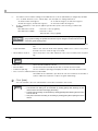
For Safety
Key to Symbols
The symbols in this manual are identified by their level of importance, as defined below. Read the
following carefully before handling the product.
You must follow warnings carefully to avoid serious bodily injury.
WARNING
CAUTION
Provides information that must be observed to prevent damage to the equipment or loss of
data.
Possibility of sustaining physical injuries.
Possibility of causing physical damage.
Possibility of causing information loss.
Provides information that must be observed to avoid damage to your equipment or a
malfunction.
Provides important information and useful tips.
3
Cautions for Regarding Installation
WARNING
CAUTION
4
Do not block the air vents on this product.
Blocking the air vents may result in internal heat build-up and fire.
Do not install in the following types of places.
Tight spaces where ventilation is poor, such as in a closet or on a bookshelf
On a rug or bed
Do not install or store in an unstable place (such as on a wobbly or tilted surface),
in reach of children, or in a place subject to vibration from other machines.
There is a risk that it could drop or fall over, resulting in injury.
Do not install in places where there is excessive moisture or dust, risk of getting
wet, direct sunlight, severe changes in temperature and humidity, or close to
heating and cooling devices.
There is a risk of electric shock, fire, and malfunction or failure of this product.
When lifting the product, maintain a comfortable posture.
Lifting the product in the improper posture may result in injury.
When lifting the product, be sure to hold the parts specified in the manual.
If you hold other parts of the product and lift the product, the product may fall or your
fingers may get caught when lowering the product, resulting in injury.
Cautions for the Power Source
WARNING
CAUTION
Use only the type of power source indicated on the product's label.
Use of the wrong type of power source may result in electric shock or fire.
Be careful when handling the power plug.
Mishandling may result in fire.
Do not leave plugged into a power source with foreign matter such as dust on it
Firmly insert the prongs of the power plug all the way
For safety reasons, be sure to ground the power cord.
The power cord supplied with the product has a 3-pin cable with a power system
grounding (PE) terminal, so connect it to an outlet that is grounded securely.
Do not use a damaged power cord.
This may result in electric shock or fire.
If the power cord is damaged, consult your dealer for repairs.
Observe the following when handling the power cord.
Do not modify the power cord
Do not place heavy objects on the power cord
Do not bend, twist or pull the power cord by force
Do not wire the cord near heating appliances
Do not connect or disconnect the power plug with wet hands.
This may result in electric shock.
Do not plug the power cord into an outlet with many other cords connected to it.
This may result in heat build-up and fire.
Do not affix the power cord to a connector or power outlet using an adhesive, etc.
There may be a risk of fire.
Regularly disconnect the power plug from the outlet and clean the base of the
prongs and between the prongs.
If you leave the power plug connected to an outlet for a long time, the base of the power
plug prongs may become dusty, which may result in short circuit and fire.
When you disconnect the power plug from the outlet, be sure to turn off the power
and hold the plug as you pull.
If you stretch the power cord, it may become damaged, which could result in electric
shock or fire.
Be sure to plug the power cord directly into a power outlet.
Be sure to place the product near a power outlet so that the power plug can be
disconnected immediately in the case of a malfunction.
For safety, be sure to disconnect the power plug from the outlet when you will not
be using the product for a long time.
5
Cautions for Using
WARNING
CAUTION
6
Do not install in a place where volatile substances, such as alcohol or paint
thinner, are present or in a place where there is fire.
This may result in electric shock or fire.
Do not continue to use under abnormal conditions such as smoke, unusual odors
or sounds.
This may result in electric shock or fire.
Immediately turn off the power, disconnect the power plug from the outlet, and contact
your dealer or the Epson Repair Center about repairs. Servicing the product yourself is
dangerous, so never attempt it.
If a foreign object, water or other liquid enters the product, do not continue to use
it.
This may result in electric shock or fire.
Immediately turn off the power, disconnect the power plug from the outlet, and contact
your dealer or the Epson Repair Center about repairs.
Do not perform any disassembly other than those mentioned in this manual.
Do not attempt to service the product yourself
This may result in injury, electric shock, fire or malfunction.
Do not use flammable gas sprays inside or around this product.
There is a risk that gas will build up and a spark may cause a fire.
Do not insert or drop metal or flammable objects into the air vents or other
openings.
This may result in electric shock or fire.
In the event of damage to the liquid crystal display, be careful in handling the
liquid crystal material inside the display.
In the event of any of the following conditions, perform first aid measures.
If the material adheres to your skin, wipe off the material, rinse your skin with water,
and thoroughly wash your skin with soap.
If the material gets into your eyes, wash out the material for at least 15 minutes with
clean water and then get a diagnosis from a physician.
If the material is swallowed, thoroughly wash your mouth with water, drink a large
amount of water and spit out the material, and then consult a physician.
Do not step or place heavy objects on top of the product.
Be especially careful in households with small children. There is a risk that it could fall
over or break, resulting in injury.
When attaching various cables and options, be sure to attach them in the correct
direction and using the correct procedure.
There may be a risk of fire or injury. Follow the instructions in the manual to correctly
attach them.
For safety reasons, if you move this product, first check that the power is off, the
power plug is disconnected from the outlet, and all of the wires are disconnected.
When storing or transporting this product, do not tilt it, stand it on end, or turn it
upside down.
There may be a risk of ink leakage.
CAUTION
When the battery inside the product needs to be replaced, contact your dealer or
Epson's repair services.
There may be a risk of explosion if it is replaced with an incorrect battery type.
Do not touch the fixed blade of the autocutter with bare hands.
Doing so may cause injury.
When replacing the ink cartridges, be careful that the ink does not contact your
eyes or skin.
If ink gets into your eyes, immediately flush them with water, and if it gets onto your skin,
immediately wash the area with soap and water. Otherwise you may have bloodshot
eyes or a mild inflammation. In the rare event that there is a problem, immediately
consult a physician.
Do not disassemble the ink cartridges to replenish or refill the ink.
Do not shake the ink cartridge too hard.
The ink cartridge may leak if you shake it too much.
Store ink cartridges out of the reach of children. Also, do not ingest the ink.
Do not brush your hands against the edges of printing paper.
Since the edges of paper are thin and sharp, there may be a risk of injury.
7
About this Manual
Aim of the Manual
This manual was created to provide information on development, design, and installation of POS
systems and development and design of printer applications for developers.
Manual Content
The manual is made up of the following sections:
8
Chapter 1
Overview and Basic Operations
Chapter 2
Setup
Chapter 3
Preinstalled OS Information
Chapter 4
Utility
Chapter 5
Setting the Printer Driver
Chapter 6
Application Development Information
Chapter 7
Maintenance
Appendix
Problems and Solutions
Product Specifications
Supplies
Contents
■ For Safety .............................................................................................................................. 3
Key to Symbols ........................................................................................................................................3
Cautions for Regarding Installation ......................................................................................................4
Cautions for the Power Source..............................................................................................................5
Cautions for Using...................................................................................................................................6
■ About this Manual ................................................................................................................ 8
Aim of the Manual .................................................................................................................................8
Manual Content .....................................................................................................................................8
■ Contents................................................................................................................................ 9
Overview and Basic Operations ................................................ 13
■ Features............................................................................................................................... 13
Accessories ...........................................................................................................................................15
■ Function............................................................................................................................... 16
■ Post-Printing Verification Settings...................................................................................... 19
When an Unrecoverable Missing Dot Occurs ...................................................................................21
■ Parts Name and Function .................................................................................................. 22
Front .......................................................................................................................................................22
Back .......................................................................................................................................................23
■ Basic Operations ................................................................................................................ 25
Power On/Off ........................................................................................................................................25
Turning On/Off the Power of the Printer .............................................................................................26
Touch Panel Operations ......................................................................................................................27
Printer status ..........................................................................................................................................29
Verifying the Ink Level...........................................................................................................................30
Ink Cartridge Replacement Procedure.............................................................................................30
Replacing the Paper............................................................................................................................31
Ejection Angle of Printed Paper .........................................................................................................34
Printer Buttons .......................................................................................................................................34
Setup............................................................................................. 35
■ Flow of Setup....................................................................................................................... 35
■ Installing the Printer............................................................................................................ 36
Installation .............................................................................................................................................36
■ Connecting the Cable....................................................................................................... 37
Connecting LAN cable........................................................................................................................38
Connecting power cord......................................................................................................................39
Connecting a Barcode Reader .........................................................................................................41
9
■ Loading the Paper.............................................................................................................. 42
■ Initial Settings...................................................................................................................... 46
■ Loading the Ink Cartridge ................................................................................................. 47
■ Attaching/Adjusting the Paper Ejection Tray .................................................................. 49
Preinstalled OS Information ........................................................51
■ Preinstallation Information................................................................................................. 51
HDD version .......................................................................................................................................... 52
■ Recovery............................................................................................................................. 53
Items to Verify Beforehand.................................................................................................................. 53
Procedure ............................................................................................................................................. 53
Utility..............................................................................................55
■ Printer power ON/OFF ........................................................................................................ 55
■ TM-C3400LT Utility ............................................................................................................... 56
■ Printer status........................................................................................................................ 57
■ Printer power and backlight brightness control.............................................................. 61
■ Touch Panel Utility .............................................................................................................. 62
Setting ................................................................................................................................................... 62
Calibration ............................................................................................................................................ 64
Setting the Printer Driver ..............................................................65
■ How to Use the Printer Driver ............................................................................................. 65
How to Display the Printer Driver ........................................................................................................ 65
Registering User Defined Media......................................................................................................... 66
Favorite Setting..................................................................................................................................... 67
Information for User Definition............................................................................................................. 70
Barcode Printing .................................................................................................................................. 71
2D Symbol Font Settings ...................................................................................................................... 84
Barcode and 2D Symbol Font Printing on .NET Environment .......................................................... 91
Functions of the Printer Driver............................................................................................................. 93
■ Setting the Printer Driver .................................................................................................... 99
Post-Printing Verification Settings........................................................................................................ 99
Notification Settings ........................................................................................................................... 106
Media Loading Settings .................................................................................................................... 108
Media Position Detection.................................................................................................................. 110
Panel Button Settings ......................................................................................................................... 111
Sensor Adjustment ............................................................................................................................. 113
Setting EPSON Status Monitor 3 ........................................................................................................ 115
Setting the Post-Printing Movements ............................................................................................... 121
10
Application Development Information.................................... 123
■ Overview........................................................................................................................... 123
■ Printer Driver...................................................................................................................... 123
■ Utilities and Manuals ........................................................................................................ 124
Download............................................................................................................................................125
■ Printer Driver and Utility.................................................................................................... 126
Function List .........................................................................................................................................126
Setting the Printer ...............................................................................................................................127
Acquiring Printer Status......................................................................................................................129
■ TM-C3400-LT API ............................................................................................................... 131
■ TM-C3400-LT Reference Library ...................................................................................... 132
TMC34LT_PrinterPowerOn ..................................................................................................................132
TMC34LT_PrinterPowerOff...................................................................................................................132
TMC34LT_SetBrightness.......................................................................................................................133
TMC34LT_SetPrinterBin ........................................................................................................................134
TMC34LT_GetPrinterBin.......................................................................................................................136
■ Sample Program............................................................................................................... 137
■ Application Specification to Develop............................................................................ 138
Character Size to Print .......................................................................................................................138
Print Barcode / 2D Symbol Data on the Graphic Data .................................................................138
When Extremely High Reliability and Safety are Required ............................................................138
Maintenance ............................................................................. 139
■ Replacing the Paper ........................................................................................................ 139
Replacing Roll Paper with Roll Paper...............................................................................................140
Replacing Fanfold Paper with Fanfold Paper .................................................................................144
Changing From Roll Paper to Fanfold Paper ..................................................................................148
Changing From Fanfold Paper To Roll Paper ..................................................................................154
■ Setting the Media Position Detection ............................................................................. 161
Setting Method ...................................................................................................................................161
■ Head Cleaning ................................................................................................................. 163
Manual Head Cleaning.....................................................................................................................163
Manual Head Cleaning during printing ..........................................................................................164
Nozzle Check ......................................................................................................................................165
■ Gap Adjustment............................................................................................................... 166
Gap Adjustment Operation Procedure...........................................................................................166
■ Self-test.............................................................................................................................. 167
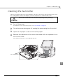
■ Cleaning the Autocutter.................................................................................................. 169
■ Exterior Surface Cleaning................................................................................................ 170
11
■ Preparing for Transport .....................................................................................................171
■ Managing the Printer Driver / Printer Settings ................................................................172
Printer Driver Functions ...................................................................................................................... 172
Upgrading the Printer Driver ............................................................................................................. 173
Destination for the Printer Driver Setting.......................................................................................... 174
Printer Setting ..................................................................................................................................... 175
■ To Customers who Plan to Keep the Product in Operation 24 Hours a Day................177
Setting the Hard Disk Motor to Stop................................................................................................. 177
■ Restrictions ........................................................................................................................180
Appendix....................................................................................181
■ Problems and Solutions ....................................................................................................181
Power On / Off Problems................................................................................................................... 181
Screen Control Problems .................................................................................................................. 182
Printout is Not Satisfactory ................................................................................................................ 183
Paper is Not Cut Cleanly................................................................................................................... 184
Cannot Read Barcode ..................................................................................................................... 184
■ Product Specifications .....................................................................................................185
Basic Specifications ........................................................................................................................... 185
Printing Specifications ....................................................................................................................... 186
Reliability............................................................................................................................................. 187
Environmental Conditions................................................................................................................. 189
Paper Specifications.......................................................................................................................... 190
Print Area and Cutting Position ........................................................................................................ 203
Paper Ejection Tray ............................................................................................................................ 211
Ink Cartridge ...................................................................................................................................... 211
■ Supplies .............................................................................................................................212
Media.................................................................................................................................................. 212
Ink Cartridge ...................................................................................................................................... 212
12
Chapter 1 Overview and Basic Operations
Overview and Basic Operations
Features
This product is a 3-color inkjet label printing terminal with Windows-based control functions and a builtin LCD touch panel.
Environmental Durability
❏ Guaranteed to a wide range of temperature (0 to 40C {32 to 104 F}) to support installation and use
in locations with no air conditioning
❏ Touch panel operation that tolerates hands with dirt and moisture on them (equivalent to IPX2)
❏ Creation of color labels using pigment ink with high light resistance and water resistance
❏ Printer's power can be turned off when printer is not being used for printing to reduce standby power
consumption (Can also be controlled from an application developed by the customer.)
High Productivity
❏ High-speed printing up to 92 mm/s (Printing width 56 mm, 360 x 180 dpi)
❏ Support for high-capacity fanfold paper to save time required for paper replacement
❏ Roll paper and ink cartridge can be replaced simply by performing operations at front of printer
❏ Easy drop-in paper loading
❏ High reliability system to prevent missing dots with auto nozzle check system installed.
❏ Reprint function allows printing to the page that was not printed after solving paper jam error or an
error of paper out.
❏ Labels can be cut one by one using autocutter
Easy Operability
❏ Screen angle and brightness can be adjusted
❏ Small footprint which is smallest in its class in the industry (300 mm (W) x 312 mm (D) x 345 mm (H))
(*excluding the projections, including the rear cover)
❏ Multiple printed sheets can be stored in the paper ejection tray. The paper ejection tray cannot
store multiple sheets of roll paper.
13
1
Software Development
❏ Printer uses Windows POS Ready 2009 and has a 250GB HDD.
❏ Comes with a printer driver. Also supports printing from commercially available label applications.
❏ The printer driver includes barcode and 2D symbol generation functions.
❏ Supports printing from a .NET environment.
❏ APIs for setting the printer and LCD brightness, etc. are available for controlling the product from an
application. In addition, functions for obtaining/notifying the status of the printer are also available.
❏ The printer has a re-printing function. It is not necessary to redo a printing sequence after recovering
from an error.
❏ Sample printing programs using the printer driver (languages: C++, C#, VB6.0, VB.NET)
Printing
❏ High-speed printing
• 92 mm/s (printing width 56 mm, 360 dpi × 180 dpi, bi-directional printing)
• 47 mm/s (printing width 56 mm, 360 dpi × 360 dpi, bi-directional printing)
The print speed is different depending on the resolution and the printing width.
❏ Color printing
• CMY 3-color printing
• Print resolution: Plain Media, Plain Media Label 360 dpi × 180 dpi, 360 dpi × 360 dpi
: Others 360 dpi × 360 dpi, 720 dpi × 360 dpi
(dpi: dots per 25.4 mm (dots per inch))
• Each color has 4 gradations
❏ Supports printing on various types of paper
• Roll paper, Fan-fold paper
• Receipt, Black Mark Receipt, Full-page Label, Die-cut Label, Black Mark Die-cut Label
(Detects positions of black marks and gaps between labels)
• Plain Media, Plain Media Label, Fine Media, Fine Media Label, PET Film, Synthetic Media Label
• Wrist Band
❏ System to prevent ink from smearing out of the printable area such as on the backing paper of Diecut Label.
❏ System to prevent missing read or missing color caused by missing dots.
14
Chapter 1 Overview and Basic Operations
Accessories
Unpacking
• This product (TM-C3400-LT)
• Roll paper (for checking initial movement)
• Ink cartridge (Model number: SJIC15P)
• Paper ejection tray
• Paper feed guide (for fanfold paper: attached on the rear of the fanfold paper cover)
• Power cord
• Recovery disk
1
• Instruction sheet
• User’s Manuals (for main unit)
The power cord may not be included with the printer.
15
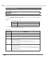
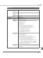
Function
Category
Control part
Function
Recommended
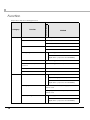
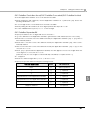
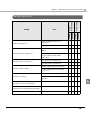
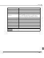
This product offers the following functions.
Method
Power on
Press the power switch.
Power off
Press the power switch.
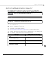
Shut down Windows.
Set password
Set in BIOS.
Set in Windows.
Change brightness
Set using specific utility.
Can be embedded into the customer's
application. (A specific API is available)
Printer
Touch panel calibration
Operate using specific utility.
Buzzer when touch panel is
touched
Operate using specific utility.
Adjust speaker volume
Set in Windows.
Switch boot drive
Switch to DVD drive, etc. in BIOS.
Power on/off
Press the power switch.
Operate using specific utility.
Can be embedded into the customer's
application. (A specific API is available)
Printing applications
Commercially available printing applications
can be used.
Printing applications developed by the customer
can be used.
Control printing
Set using printer driver.
Can be embedded into the customer's
application. (A specific API is available)
16
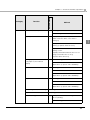
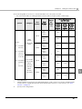
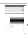
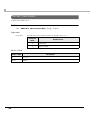
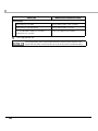
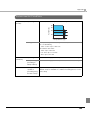
Category
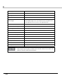
Printer
Function
Print barcodes, 2D symbols
Recommended
Chapter 1 Overview and Basic Operations
Method
Set using printer driver.
Print an image file from an application.
Display printer status
Displayed in specific utility.
(Starts when the status of the device
changes)
1
Displayed in EPSON Status Monitor3 while
printing. (A printer driver function)
Displayed in the fatal error notification
settings screen.
(Displayed if EPSON Status Monitor 3 is not
being used at the time of error)
(A printer driver function)
Change paper*
(Roll paper to/from fanfold
paper)
Auto cut
Operate using specific utility.
Can be embedded into the customer's
application. (A specific API is available)
Set using printer driver.
Press the CUT button.
Can be embedded into the customer's
application. (A specific API is available)
Paper feed
Set using printer driver.
Press the FEED button.
Can be embedded into the customer's
application. (A specific API is available)
Post-Printing Verification Settings
Set using printer driver.
Reprint after an error
Set using printer driver.
Head Cleaning
Set in printer driver's Post-Printing Verification
prior to printing.
Operate using printer driver.
17
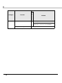
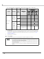
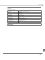
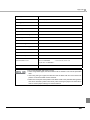
Printer
Function
Media position detection
Recommended
Category
Method
Set using printer driver.
Can be embedded into the customer's
application. (A specific API is available)
Other printer settings
Set using printer driver.
*The printer needs to be set the printer and the printer driver.
18
Chapter 1 Overview and Basic Operations
Post-Printing Verification Settings
This product monitors dot missing periodically with the auto nozzle check system, and performs the auto
head cleaning if any dots are missing. Select from 6 modes that are available for different levels of
requirements for print quality and movement.
When extremely high reliability and safety are required, be sure to detect dot missing using an
application in addition to the printer driver setting. For the details, see "When Extremely High Reliability
and Safety are Required" on page 138.
Sets this function from [Post-Printing Verification Settings] on [Maintenance And Utilities] of the printer
driver. The printer's Post-Printing Verification Settings can be checked using Self-test Mode. For the
details, see "Self-test" on page 167.
• High Reliability Mode (Void Image Print)
Missing dots check is performed after printing each page to check that dot missing has not
occurred. When dot missing is detected, the Void Image Print is performed at the bottom of the
previous page. And after the dot missing is resolved by the auto head cleaning, reprinting starts from
the corresponding page.
The Void Image is printed in solid black by default; however, other image files can also be
registered. Since dots are missing for the page on which the Void Image is printed, take proper
action such as discarding it.
• High Reliability Mode (Reprint)
Missing dots check is performed after printing each page to check that dot missing has not
occurred. When dot missing is detected, the following screen of the EPSON Status Monitor 3 is
displayed. Select the next operation from [Restart printing] (printing the next data) and [Reprint]
(reprinting after dot missing is resolved by the auto head cleaning.)
• Economy Mode for Low Print Volume (Void Image Print)
Missing dots check is performed after printing each page with removing the timer cleaning.
When dot missing (more than neighboring 2 dots missing) is detected, the Void Image Print is
performed at the bottom of the previous page. And after the dot missing is resolved by the auto
head cleaning, reprinting starts from the corresponding page.
The Void Image is printed in solid black by default; however, other image files can also be registered.
• Economy Mode for Low Print Volume (Reprint)
Missing dots check is performed after printing each page with removing the timer cleaning.
When dot missing (more than neighboring 2 dots missing) is detected, the EPSON Status Monitor 3 is
displayed. Select the next operation from [Restart printing] (printing the next data) and [Reprint]
(reprinting after dot missing is resolved by the auto head cleaning).
When customer want to select this mode, do NOT uncheck [Use EPSON Status Monitor 3] of [Driver
Preferences] in [Driver Utilities] tab.
• Anti-missing Read Mode
Does not perform missing dots check after printing each page, but checks missing dots while not
printing.
19
1
• Anti-missing Color Mode
Does not perform missing dots check after printing each page, but checks missing dots while not
printing. Prevents missing colors due to missing dots on the condition with adjoining 2 dots in above
and below or 3 dots in all nozzles. Does not perform head cleaning to missing dots with less than 2
dots that are not adjoining.
These functions do not guarantee a 100 percent prevention of dot missing.
Small amount of ink is used for detecting nozzle clogging.
The auto head cleaning is performed automatically after nozzle clogging is detected. Ink
is expended during the head cleaning.
Nozzle clogging detect function cannot be disabled.
When you want to select [High Reliability Mode (Reprint)] or [Economy Mode for Low
Print Volume (Reprint)], do not uncheck [Use EPSON Status Monitor 3] of [Driver Preferences] in [Driver Utilities] tab.
In the High Reliability Mode or Economy Mode for Low Print Volume, printing takes more
time since the missing dots check is performed after printing each page.
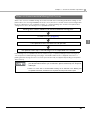
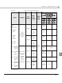
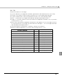
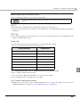
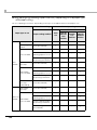
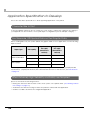
When an unrecoverable missing dot occurs, the printer operates differently for each mode as shown
below.
Printer Status
Post-Printing
Verification
Number of Missing
Dots
Fatal error
Maintenance error
High Reliability Mode
High Reliability Mode
Economy Mode for
Low Print Volume
Economy Mode for
Low Print Volume
Anti-missing Read
Mode
Anti-missing Read
Mode
1 dot
2 or more dots
Anti-missing Color
Mode
Adjoining 2 dots
3 or more dots
Printer Usability
(Missing Dot
Acceptable Print
Mode*)
X
(The printer needs repair)
* For details on the Missing Dot Acceptable Print Mode, refer to "When an Unrecoverable Missing Dot
Occurs" on page 21.
20
Chapter 1 Overview and Basic Operations
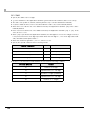
When an Unrecoverable Missing Dot Occurs
When 1 dot of unrecoverable missing dot is detected with the Post-Printing Verification Settings for the
printer driver set to the High Reliability Mode /Economy Mode for Low Print Volume /Anti-missing Read
Mode, the printer becomes in fatal error status. To continue printing, turn off and on the printer and
change the mode to the Missing Dot Acceptable Print Mode.
Missing dots check detects an unrecoverable missing dot.
A fatal occurs (page 59)
1
The operator turns off and on the printer.
The printer starts up in the Missing Dot Acceptable Print Mode
In the Missing Dot Acceptable Print Mode, it takes long to complete printing because missing dots
check is performed after printing each page. The EPSON Status Monitor 3 appears each time of
printing until the missing dot error is resolved. (The window may not appear depending on the printer
driver version.)
In the Missing Dot Acceptable Print Mode, EPSON Status Monitor 3 is displayed even if
[Use EPSON Status Monitor 3] is not selected in [Driver Preferences] from the [Driver
Utilities] tab.
When 2 or more dots of unrecoverable missing dot is detected in the Missing Dot
Acceptable Print Mode, maintenance is requested and the printer needs repair.
21
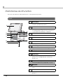
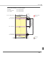
Parts Name and Function
This section describes the name and function of each part in the product.
Front
1
Touch panel
Displays the menu and messages. Touch the
screen to operate the product.
1
2
2
4
3
5
Based on the settings, plays a sound when the
touch panel buttons are pressed, when an error
occurs, and when printing is completed.
3
6
7
CUT button
Push this button to cut the paper.
4
FEED button
Push this button to feed the paper.
8
9
10
Speaker
5
Release lever
Pull to open the roll paper cover.
11
6
Ink cartridge cover
Open to set/replace the ink cartridge.
7
Roll paper cover
Open to set/replace the paper.
8
Power lamp
A green light will light up when the power of the
product is on. The light will turn off when the
power is off.
9
USB connector (x2)
Connect a USB memory, keyboard, or mouse.
10
USB cover
Use the cover when USB connectors are not
used.
11
Power switch
Push this button to turn on/off the power of the
product.
22
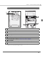
Chapter 1 Overview and Basic Operations
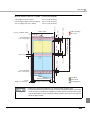
Back
1
2
3
4
1
6
5
1
Rear cover
Remove when connecting connectors.
2
Fanfold paper cover
Open to insert fanfold paper.
3
Paper feed guide
Install the guide when you use the fanfold paper.
4
Connector part
Connect each cable. For details, see "<Rear Connector Part>" on page 24.
5
Power cord hook
Prevents the power cord from piling on other cables. Be sure to pass it through the hook.
6
Cable holders
Prevents the cables from piling on each other. When connecting the LAN cable, USB cable, or audio
cables, be sure to pass them through the holder.
23
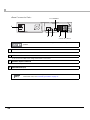
<Rear Connector Part>
*Not available.
1
2
3
4
*Never disconnect.
Never disconnect the 3 USB connectors on the right side that are initially connected on the
product.
1
Power connector
Connect the power cord.
2
LAN connector
Connect a LAN cable when using a wired LAN connection.
3
Speaker output connector
Connect the speakers.
4
USB connector (x3)
Connect a barcode reader or similar device.
To connect the rear connectors, you need to remove the rear cover. For details on how to
remove the cover, see "Connecting the Cable" on page 37.
24
Chapter 1 Overview and Basic Operations
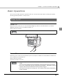
Basic Operations
This section describes the basic operation methods of the product that can be used by an operator
and the general operations of the product.
Power On/Off
Power On
When the power is turned on, the power lamp will light up, Windows will start and a screen will be
displayed, and the power of the printer will turn on.
1
❏ Press the power switch.
The printer can also be network booted from another PC that is connected via LAN.
Power Off
When the power is turned off, the printer's power off sequence will be executed, Windows will be shut
down, and the power will turn off.
❏ Press the power switch.
❏ Windows will be shut down.
To prevent operation errors, the button can be set so that it cannot be used to turn off the
power.
This can be set in [Start]-[Control Panel]-[Power Options]-[Advanced]-[Power buttons].
Do not turn off the power using the commercial circuit breaker. The printer's power off
sequence will not be executed and the ink may become clogged.
If the power is cut off due to an outage, etc., turn on/off the power of the product after the
power is restored.
25
Turning On/Off the Power of the Printer
It is possible to specifically control the power of the printer portion of the product. While the product is
operating, by turning on/off the printer only when you need to print, it is possible to reduce the standby
power consumption.
The power status of the printer can be verified using the "Printer Power ON/OFF" utility.
An API is available for turning on/off the power of the printer using the customer's application. (See "TM-C3400-LT Reference Library" on page 132)
There is no power lamp for the printer.
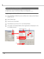
Turning On the Printer
When the printer is turned on, the printer's power on sequence will be executed, the fan will operate for
several seconds, and the printer will become ready to print.
❏ When the power switch is pressed, the power of the main unit and the printer will turn on together.
(default setting)
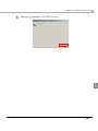
❏ If Windows is running, turn on the printer using the "Printer Power ON/OFF" utility.
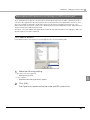
Double-click TMC34LT_POWER
on the desktop.
Press the On button. When the power of the printer turns on, the power status of the printer will
change to green.
Turning Off the Printer
When the printer is turned off, the printer's power off sequence will be executed, the fan will operate for
several seconds, and the power will turn off.
❏ Press the Off button in the "Printer Power ON/OFF" utility.
The power status of the printer will change to gray.
26
Chapter 1 Overview and Basic Operations
Touch Panel Operations
Do not place heavy objects on the touch panel. The touch panel may be damaged
because it uses glass.
Do not push or scrub the touch panel. Also, do not push it with a sharp pointed object.
Use of a touch panel protection sheet is recommended if this product is used in an environment where users' hands are easily soiled by sand, dirt, etc.
Adjusting Touch Panel Angle
You can slide the touch panel to adjust the angle so that it is easy to use.
1
Adjusting Touch Panel Brightness
The brightness of the touch panel can be adjusted using the TM-C3400LT UTILITY.
For details, see "TM-C3400LT Utility" on page 56.
1
Double-click “TMC34LT_UTIL”
2
Adjust the brightness.
on the desktop.
27
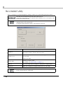
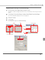
Adjusting the Beep Sound
The beep sound can be adjusted using the touch panel utility.
For details, see "Touch Panel Utility" on page 62.
28
1
Select [Start]-[All Programs]-[eGalax Touch]-[Configure Utility].
2
In the [Setting] tab, under [Beep], adjust the beep sound.
Chapter 1 Overview and Basic Operations
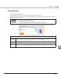
Printer status
The Printer Status utility monitors the printer's status, and when an error or warning condition occurs, it is
displayed on the screen.
After confirming the error/warning, press the [Close] button to close the screen.
When the printer is in a normal state, the "Printer Status" will not be displayed.
1
It is also possible to display the printer status display utility from "TMC34LT_UTIL” on the
desktop.
29
Verifying the Ink Level
The ink level can be verified using the Printer Status utility.
When the ink level becomes low, and it is almost time to replace the ink cartridge, a message will be
displayed onscreen. Prepare a new ink cartridge.
When it becomes time to replace the ink cartridge, a message will be displayed onscreen and the
product will stop printing. You will not be able to print until you install a new ink cartridge.
The ink cartridge that is shipped with the product is for initial ink charging. When an ink
cartridge is installed for the first time (during setup), ink will be consumed for ink charging, and you will need to replace the ink cartridge earlier than usual.
The amount of ink consumed will vary depending on the use environment and use conditions of the product.
To preserve the quality of the print head, it will become time to replace the ink cartridge
before the ink in the cartridge is completely used up.
The ink cartridge contains 3 colors of ink. Even when one particular color is specified, all
3 colors of ink are used for printing and for keeping the print head in good condition.
When the ink level of even one color comes to the lowest limit, the product stops printing.
Ink Cartridge Replacement Procedure
See "Loading the Ink Cartridge" on page 47. The same procedure can be used for replacing the
cartridge. Pull out and remove the used ink cartridge.
For the ink cartridge model, see "Ink Cartridge" on page 211.
30
Chapter 1 Overview and Basic Operations
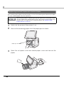
Replacing the Paper
This section describes how to replace the paper with the same type of paper when it is used up.
For details on replacing the paper, see "Replacing the Paper" on page 139.
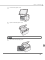
Roll Paper
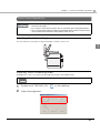
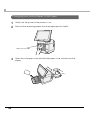
1
Pull the release lever to open the roll paper cover, and remove the roll
paper core.
1
2
Load the roll paper completely inside the printer, and while aligning the
paper to the paper ejection guide, close the roll paper cover.
Paper ejection guide
The roll paper will be automatically fed.
This completes the paper replacement procedure.
31
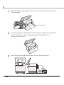
Fanfold Paper
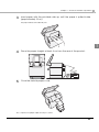
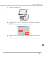
1
2
32
Open the roll paper cover and fanfold paper cover and remove the
paper.
Close the roll paper cover.
Chapter 1 Overview and Basic Operations
3
Insert paper with the printable side up, until the paper is pulled inside
(approximately 10cm).
The paper will be automatically fed.
1
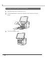
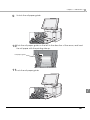
4
Place the paper straight at least 4 cm from the rear of the product.
5
Close the fanfold paper cover.
This completes the paper replacement procedure.
33
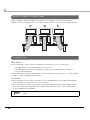
Ejection Angle of Printed Paper
Make sure paper is ejected straight from the paper ejection guides, as shown in the illustration.
If paper is not ejected straight due to such causes as an obstruction, the print result may be distorted.
Printer Buttons
FEED button
❏ Feeds the paper continuously when media position detection is set to “No Detection”.
• The paper is fed by 15 mm if FEED button is pressed once.
• If the FEED button is held down, the paper is continuously fed until the button is released.
(6 seconds at a maximum)
❏ Feeds the paper to the print starting position when media position detection is set to “Detects Black
Marks” or “Detects Margins Between Labels”.
CUT button
❏ Feeds the paper to the first auto cut position on the next page and cuts the paper automatically
when media position detection is set to “No Detection”.
❏ Feeds the paper to the autocut position by detecting the gap between the black marks or labels
and cuts the paper automatically when media position detection is set to “Detects Black Marks” or
“Detects Margins Between Labels”.
The media position detection setting is set on [Maintenance And Utilities] tab on the printer
driver.
34
Chapter 2 Setup
Setup
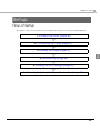
Flow of Setup
This chapter consists of the following sections along with the setup flow of the product and peripherals.
1. Installing the Printer (page 36)
2. Connecting the Cable (page 37)
3. Loading the Paper (page 42)
2
4. Initial Settings (page 46)
5. Loading the Ink Cartridge (page 47)
6. Attaching/Adjusting the Paper Ejection Tray (page 49)
35
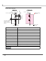
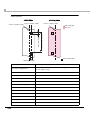
Installing the Printer
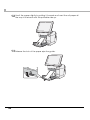
Install the product at an appropriate place, leaving enough space around the product.
If you install the product against a wall, keep the rear and sides of the product more than 10 cm from
the wall.
Do not block the air vents on this product.
Blocking the air vents may result in internal heat build-up and fire.
WARNING
Install the product horizontally on a flat, stable, and vibration-free surface.
Otherwise, the roll paper cover may not operate correctly, and your fingers may be
caught.
Do not tilt the product with the roll paper cover open.
The roll paper cover may close unexpectedly, and your fingers may be caught.
CAUTION
When carrying the product, be sure to hold the parts as shown in the picture below.
Installation
Air vents
Located on the left,
right, and back.
10cm
10cm
• Leave enough space for the roll paper cover, ink cartridge cover, and fanfold paper cover to be fully
opened.
• Protect the product from heavy impacts. They may cause defective print.
• Do not allow cables to catch or foreign matter to accumulate under the product.
36
Chapter 2 Setup
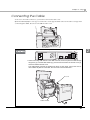
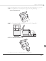
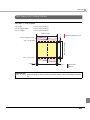
Connecting the Cable
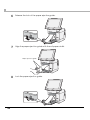
To access to the rear connectors, you need to remove the rear cover.
Open the fanfold paper cover (1), loosen the two screws (2), and then remove the rear cover (3). After
connecting the cable, be sure to re-install the rear cover.
2
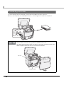
Never disconnect the cables initially connected to the USB connectors on the right.
When connecting USB devices to the USB connector, be sure to pass the cable through
the groove (1), hook the cable holder (2), pull it out from the bottom of the rear cover (3),
and then reattach the rear cover.
The cable holder prevents the cables from piling on each other. If the power cord or
other cables are piled on each other, the rear cover cannot be attached.
Groove
Cable holder
37
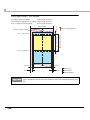
Connecting LAN cable
To connect this product to a network, connect the LAN cable to the LAN connector.
When you use the product as a standalone device, connecting the LAN cable is not required.
Be sure to pass the LAN cable through the groove (1), hook the cable holder (2), pull it out
from the bottom of the rear cover (3), and then reattach the rear cover.
The cable holder prevents the cables from piling on each other. If the power cord or other
cables are piled on each other, the rear cover cannot be attached.
Groove
Cable holder
38
Chapter 2 Setup
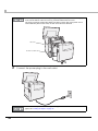
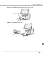
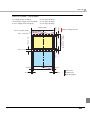
Connecting power cord
Follow the steps below to connect the product to the power supply.
Be sure to use the power cord that is included with the product, and ground it.
Be sure to use the specified power supply.
WARNING
1
Connect the power cord to the power supply connector.
2
39
Be sure to pass the power cord through the groove (1), hook the power cord hook (2), pull
it out from the bottom of the rear cover (3), and then reattach the rear cover.
The power cord hook prevents the cables from piling on each other. If the power cord or
other cables are piled on each other, the rear cover cannot be attached.
Groove
Power cord hook
2
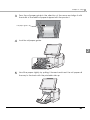
Connect the power plug to the wall outlet.
Do not turn on the power before loading the roll paper. For details on how to load the roll
paper, see "Loading the Paper" on page 42.
40
Chapter 2 Setup
Connecting a Barcode Reader
When using a barcode reader, connect it to a USB connector at the rear of the product.
2
41
Loading the Paper
This section describes how to set the paper for the first time.
For information on how to replace the paper during regular use, see "Replacing the Paper" on page
139.
The product is shipped with factory default settings set to use the label roll paper shipped
with the product.
When loading the paper for the first time (during setup), be sure to load the label roll paper
shipped with the product and perform ink cartridge charging (see "Loading the Ink
Cartridge" on page 47). When paper other than the label roll paper shipped with the product
is loaded, ink cartridge charging cannot be performed.
After completing the initial settings (see "Initial Settings" on page 46), you can replace the
paper with another. For details on how to replace the paper, see "Replacing the Paper" on
page 139.
1
2
42
Press down the release lever, and pull it to the front to open the roll
paper cover.
Unlock the roll paper guide.
Chapter 2 Setup
3
Press the roll paper guide in the direction of the arrow and align it with
the width of the label roll paper shipped with the product.
Roll paper guide
4
Lock the roll paper guide.
2
5
Unroll the paper slightly by pulling it forward and insert the roll paper all
the way to the back with the printable side up.
43
6
Release the lock of the paper ejection guide.
7
Align the paper ejection guide with the roll paper width.
Paper ejection guide
8
44
Lock the paper ejection guide.
Chapter 2 Setup
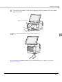
9
Close the roll paper cover while aligning the roll paper with the paper
ejection guide.
Paper ejection guide
10 Press the power switch to turn the power on.
2
Once you are finished loading the paper, perform the initial settings on the product. (See "Initial
Settings" on page 46.)
45
Initial Settings
This section describes the OS setting procedure when the power of the product is turned on for the first
time.
1
2
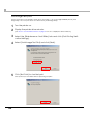
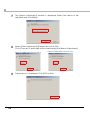
When the power of the product is turned on for the first time, the Windows Setup screen is displayed for a period of time.
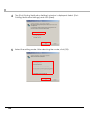
The "License Agreement" screen will be displayed. Verify the contents
and select "I accept this agreement". Click the [Next] button.
3
Windows settings such as the network driver will be automatically set.
4
The main unit will automatically restart.
5
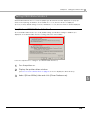
Set the product's network settings, such as the IP address, after the setup is complete.
After the product restarts, select [Start] - [Control Panel] - [Date and
Time] and display "Date and Time Properties". Set the date, time, and
time zone.
Once the initial settings are complete, load the ink cartridge and perform ink charging. (See "Loading
the Ink Cartridge" on page 47.)
46
Chapter 2 Setup
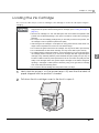
Loading the Ink Cartridge
This section describes the procedure for loading the ink cartridge for the first time and performing ink
charging.
When loading the ink cartridge for the first time, be sure to load the label roll paper
shipped with the product before loading the ink cartridge. (See "Loading the Paper" on
page 42.)
Store the ink cartridge in a cool and dark space and use it before the expiration date
printed on the individual package. Use up the ink within 6 months after opening the
package.
Do not open the ink cartridge package until you are ready to load it in the product. The
ink cartridge is vacuum packed to preserve its quality.
After storing the ink cartridge in a cold place for a long period of time, leave the ink cartridge at room temperature for 3 hours or more before using it.
Do not touch the green board on the ink cartridge. You may not be able to print correctly.
Do not disassemble or alter the ink cartridge. You may not be able to print correctly.
To enable maximum printer performance, we recommend that you use a genuine Epson
ink cartridge (model: SJIC15P). If you use an ink cartridge other than a genuine Epson
cartridge, it may adversely affect the printer hardware and print quality, and you may not
be able to obtain maximum printer performance. We do not insure the quality and reliability of ink cartridges other than genuine Epson cartridges. A fee will be charged for
repairing a damaged or failed product caused by using a non-genuine ink cartridge
even if it is during the warranty period.
Do not remove the ink cartridge from the product when you ship it.
1
2
Verify that the power is on (the power lamp is lit) and that the label roll
paper shipped with the product is loaded.
Pull down the ink cartridge cover to the front to open it.
47
2
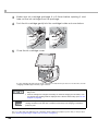
3
Shake new ink cartridge package 4 or 5 times before opening it and
take out the ink cartridge from the package.
4
Push the ink cartridge gently into the cartridge holder as shown below.
5
Close the ink cartridge cover.
The ink charging will start. When an ink cartridge is loaded in the product for the first time, the ink
charging will take approximately eight minutes.
During the ink charging, do not turn off the power or open the roll paper cover or ink cartridge cover.
If the ink cartridge and roll paper necessary for initial ink charging are not loaded, a factory default state message will be displayed in the Printer Status utility. (See "No ink
charged" on page 59)
The ink cartridge that is shipped with the product is for initial ink charging. When an ink
cartridge is loaded for the first time, ink will be consumed (for ink charging) to enable the
product to print.
Once you are finished loading the ink cartridge, attach/adjust the paper ejection tray on the product.
(See "Attaching/Adjusting the Paper Ejection Tray" on page 49.)
48
Chapter 2 Setup
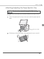
Attaching/Adjusting the Paper Ejection Tray
If you attach the paper ejection tray, you can temporarily store the printed paper in the tray.
Paper may not stay in the paper ejection tray depending on the paper curl and length.
When using the product with the paper ejection tray, attach and adjust the tray using the following
procedure.
1
Attach the paper ejection tray to the hooks under the paper ejection
table.
2
Paper ejection table
2
Pull the lever at the bottom-right of the paper ejection tray to unlock it.
49
3
50
Slide the bottom tray to align it with the paper length, and lock it.
Chapter 3 Preinstalled OS Information
Preinstalled OS Information
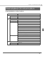
Preinstallation Information
Item
Details
Hard disk format
File system
NTFS
Volume label
TM-C3400-LT
Preinstalled software
OS
Windows Embedded POS Ready 2009
Additional packages
.NET Framework 3.5 SP1
Driver
Intel inf software
Intel chipset software utility
Intel video driver
Broadcom network driver
Conexant sound driver
eGalax touch panel driver
3
TM-C3400 printer driver
LCD brightness adjustment driver
TM-C3400 power control driver
TM-C3400 power ON program
TM-C3400 status display program
Tool
TM-C3400-LT Utility
Printer power on/off
EPSON Net SDK
TM-C3400-LT Tool
TM-C3400-LT Tool module
Default information
User
Administrator
User password
TM-C3400-LT
51
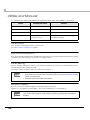
HDD version
To verify the HDD version, see HDVER.TAG in the root directory of the startup drive.
This file is in text format and can be viewed using Notepad, etc. The contents of HDVER.TAG are as
follows.
[HD Information]
MODEL=Egis-LT 011
OS=POSReady2009
LANG=English
VER=1.00.0
52
Chapter 3 Preinstalled OS Information
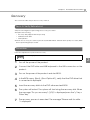
Recovery
This section describes the product recovery method.
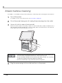
Items to Verify Beforehand
Verify the following before performing the recovery procedure.
❏ Prepare the following.
• Recovery disk (shipped with the product)
• USB-based DVD drive
• USB keyboard
❏ When the recovery procedure is performed, all data will be deleted. Back up any necessary data
before performing the procedure.
Procedure
Follow the steps below to perform the recovery.
Recovery requires 30 to 45 minutes.
1
2
3
4
5
6
7
3
Turn off the power of the product.
Connect the DVD drive and USB keyboard to the USB connectors on the
product.
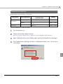
Turn on the power of the product and start BIOS.
In the BIOS menu, [Boot] - [Boot Option #1], verify that the DVD drive that
is connected is displayed.
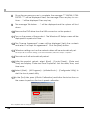
Insert the recovery disk into the DVD drive and exit BIOS.
The system will restart. The system will start using the recovery disk. When
the message "Do you recovery? (Y/N)" is displayed press the "y" key +
"Enter" key.
The recovery process is executed. The message "Please wait for while . .
." is displayed.
53
8
9
Once the recovery process is complete, the message "*** INSTALL COMPLETED ***" will be displayed. Next, the message "Press any key to continue . . ." will be displayed. Press any key.
The message "Shutdown . . ." will be displayed and the system will shut
down.
10 Remove the DVD drive from the USB connectors on the product.
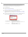
11 Turn on the power of the product.
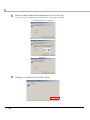
The Windows XP Setup screen will be
displayed for a period of time.
12 The "License Agreement" screen will be displayed. Verify the contents
and select "I accept this agreement". Click the [Next] button.
settings such as the network driver will be automatically set.
13 "Windows
Set the product's network settings, such as the IP address, after the setup is complete."
14 The main unit will automatically restart.
15 After the product restarts, select [Start] - [Control Panel] - [Date and
Time] and display "Date and Time Properties". Set the date, time, and
time zone.
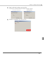
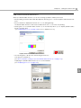
16 Select [Start] - [All Programs] - [eGalaxTouch] - [Configurate Utility] to
start the touch panel utility.
17 In the [Tool] tab, press [4 Points Calibration] and follow the instructions on
the screen to perform the touch panel calibration.
This completes the recovery process.
54
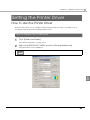
Chapter 4 Utility
Utility
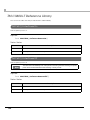
Printer power ON/OFF
This is for managing the power of the printer.
A shortcut to this utility is created on the desktop.
<Storage location of the execution file>
C:\Program Files\EPSON\TM-C3400-LT TOOL\TMC34LT_POWER.exe
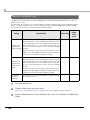
Item
Description
ON
Turns on the power of the printer
OFF
Turns off the power of the printer
4
Indicates the power status of the printer.
Printer's power status
Green: the power of the printer is on.
Gray:
Close
the power of the printer is off.
Closes [Printer power ON/OFF].
55
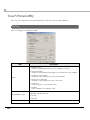
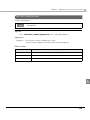
TM-C3400LT Utility
This is for setting the touch panel brightness settings, media source, and verifying the printer status.
This utility cannot be started if the power of the printer is not on.
If the power of the printer is off, use [Printer power ON/OFF] to turn on the power of the
printer before starting the utility.
A shortcut to this utility is created on the desktop.
<Storage location of the execution file>
C:\Program Files\EPSON\TM-C3400-LT TOOL\TMC34LT_UTIL.exe
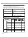
Item
Brightness
Description
Adjusts the display brightness.
The adjusted value is saved in TMC34LT_UTL.ini.
Sets the media source. Select from the following.
Media source
Roll media
Fanfold media
Printer status
Displays the printer status.
(For details, see "Printer status" on page 57.)
Cancel
Closes the utility without saving the settings and changed value.
Save&exit
Saves the settings and changed value and closes the utility.
The media source can be changed only when there is no paper loaded, the roll paper cover
is shut, and the printer is in an idle state.
56
Chapter 4 Utility
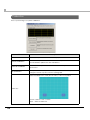
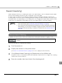
Printer status
This displays the printer status.
When the printer is in a normal state, the program will not be displayed.
When an error occurs, the window is automatically displayed, and the printer status can also be verified
using the TM-C3400LT Utility.
This utility is registered in Startup.
<Storage location of the execution file>
C:\Program Files\EPSON\TM-C3400-LT TOOL\TMC34LT_Mon.exe
Item
Description
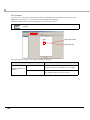
Message
Displays the printer status.
The scroll buttons on the right can be used to scroll the message.
Ink status
Displays the ink level.
Close
Closes the [Printer status] window.
Hides the screen until the printer changes to another status that needs to be notified.
4
57
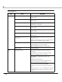
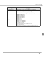
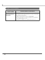
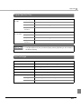
Message List
Type
Information
Status
Power off processing
Message
Processing power off.
Please wait.
Executing
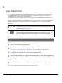
Executing.
Please wait.
Printing the void image.
Missing dots are detected.
Printing the void image.
Printing the nozzle check pattern
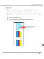
Printing the nozzle check pattern.
Please wait.
Executing the head cleaning
Cleaning the print head.
Please wait.
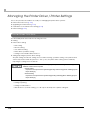
Printing
Printing.
Please wait.
Mechanical adjestment is
required soon
Mechanical adjustment inside the printer will be
required soon.
Please contact the store where you purchased
the product or an Epson service center.
Ink cartidge nearly empty
The time to replace the ink cartridge is close.
Please prepare a new ink cartridge.
Epson brand products are recommended.
Error
Ready to print
Ready to printer.
Maintenance error
Mechanical adjustment inside the printer is
required.
Contact the store where you purchased the
product or an Epson service center.
Uncleanable clogged print head nozzles
detected.
Please turn the printer off.
Contact the store where you purchased the
product or an Epson service center.
Communication with the printer failed.
Please turn off the power and then turn it back
on.
If the same error occurs, contact the store where
you purchased the product or an Epson service
center.
58
Chapter 4 Utility
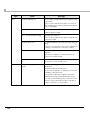
Type
Error
Status
Faital Error
Message
Printer error. (xxx)*
Please turn the printer off.
Remove any foreign objects from inside the
printer then turn the printer back on. If this is the
first print job, please, check to make sure all
packing materials and parts have been
removed.
*xx indicates the Fatal error code.
Low temperature error
Low temperature error.
The ambient temperature may be too low. Set
the ambient temperature within 0C {32F} and
40C {104F}, turn off the printer and then turn it
back on.
High temperature error
High temperature error.
The ambient temperature may be too high. Set
the ambient temperature within 0C {32F} and
40C {104F}, turn off the printer and then turn it
back on.
Roll media cover open
Roll media cover open.
Close the roll media cover.
Ink cartidge cover open
Ink cartridge cover open.
Close the ink cartridge cover.
Media jam (roll media)
Media jam.
Open the roll media cover and remove the
jammed media, then close the roll media cover.
Media jam (fanfold media)
Media jam.
Open the roll media cover and remove the
jammed media.
Then close the roll media cover and reload the
fanfold media.
No ink charged
Install the ink cartridge for initial charging and
load the roll media for initial setting included in
the product package.
Replace ink cartridge
Replace the ink cartridge.
Epson brand products are recommended.
Ink cartridge needs replacing, or cannot be recognized correctly.
Replace the ink cartridge.
Epson brand products are recommended.
59
4
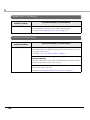
Type
Error
Status
Media remaining error
Message
New media is loaded without removing the existing media.
Remove the loaded new media once. Remove
any media which is still in the printer and load the
new media again.
Out of media (roll media)
Media is not loaded.
Please load the media.
Out of media (fanfold media)
Media is not loaded.
Remove any media which is still in the printer and
load new media.
Media position error
Loaded media does not match the specified setting.
Set the correct media, or check the media layout
settings or media position detection settings.
Media size error
Driver media size does not match the media
loaded.
Modify the media size on the printer driver to
match the loaded media.
Media source error
Media source mismatch.
Specify the correct media source.
Warning
Uncleanable clogged print head
nozzles
Uncleanable clogged print head nozzles
detected.
The print result may be affected.
Nozzle check operation is changed to ensure the
reliability of the print result.
The printer is searching clogged nozzles after
printing each page; printing may take longer.
You can continue printing, but contact the store
where you purchased the product or an Epson
service center as soon as possible.
60
Chapter 4 Utility
Printer power and backlight brightness control
This is a tool that is registered in Startup and used.
When logging into a PC (in the default setting, automatic login as Administrator), the following is
executed. In addition, when the PC is shut down, the power of the printer is turned off.
• Turns on the power of the printer
• The brightness value set in TM-C3400LT Utility is read and applied to the brightness of the display.
This utility is registered in Startup.
<Storage location of the execution file>
C:\Program Files\EPSON\TM-C3400-LT TOOL\TMC34LT_INIT.exe
4
61
Touch Panel Utility
This is a tool for setting the touch panel and beep sound, and for performing calibration.
Setting
This is for setting the touch panel settings.
Item
Description
Beep On Touch
A beep sound is played when the touch panel is touched.
Beep On Release
A beep sound is played when finger is removed from the touch panel.
Beep
Beep From System Beep
The beep sound is played from the system speaker.
Beep From Sound Card
The beep sound is played from the sound card.
Frequency
Sets the frequency of the beep sound.
Duration
Sets the duration of the beep sound.
Sets the reference points for touch panel linearization. One of the following values can be selected.
Linearizatation Style
9 Points
25 Points
Double Click Time
62
Sets the time between touches to be identified as a double-click.
Chapter 4 Utility
Item
Double Click Area
Description
Sets the range of touches to be identified as a double-click.
Sets the touch settings. Select from the following:
Mode
[Normal Mode], [Click On Touch], [Click On Release],
[Click On Touch Without Moving Cursor], [Desktop Mode]
Enable Constant Touch
Enables constant touch.
Enable Auto Right Click
Enables auto right click.
Option
Enable Touch
Enables touch.
Enable Cursor Stabilization
Enables cursor stabilization.
Constant Touch Area
Specifies the range of the constant touch area.
Auto Right Click Time
Specifies the touch duration to be identified as an auto right click.
4
63
Calibration
This is for performing touch panel calibration.
Item
Linearizatation Curve
4 Points Calibration
Description
The currently set linearization curve is displayed.
Calibration is performed based on 4 reference points.
The linearization parameters are maintained.
Clear and Calibrate
The linearization parameters are cleared and a 4 points calibration is
performed.
Linearizatation
To improve the linearity of the touch panel, linearization is performed
using the reference points set in the [Setting] tab.
Perform a draw test to verify the accuracy of the touch panel.
Draw Test
Clear : Clears the test contents.
Quit : Quits the draw test.
64
Chapter 5 Setting the Printer Driver
Setting the Printer Driver
How to Use the Printer Driver
The printer driver allows you to change the print settings and also provides some utilities such as
checking the printer status and cleaning the print head.
How to Display the Printer Driver
1
Click [Printers and Faxes].
2
Right-click [EPSON TM-C3400], and click [Printing References].
Click [Printers and Faxes] on [Start] menu.
The printer driver screen is displayed.
This is displayed when the registered name of the printer is [EPSON TM-C3400].
5
65
Registering User Defined Media
If the paper size to use is not in Media Layout, register the user defined media.
The registered layout will be stored in [Favorite Setting] to use from application of users.
Registering User Defined Media
1
Click [Add/Del] of [Media Layout] on [Main] tab to display [User Defined
Media Layout].
2
Select Media Type.
3
Enter the size of the paper.
4
Enter Media Layout Name. This is User Defined Media.
5
Click [Add]. User Defined Media will be registered and displayed on the
list of [Media Layout].
Registered paper type
(1)
(4)
(2)
(5)
66
(3)
Chapter 5 Setting the Printer Driver
Favorite Setting
[Favorite Setting] is the function to administer print setting of the printer driver into one.
The setting from [Main] and [Page Layout] tab such as Media Type, Media Layout (including User
Defined Media) are included.
[Main] tab
Favorite Setting
[Page Layout] tab
5
67
Features
• When printing from application, the print setting registered on [Favorite Setting] can be selected as
default setting.
It is recommended to register the setting in favorite setting after executing print setting by clicking [Save
As Favorite Setting].
• A number of setting can be registered on [Favorite Setting].
For example, if the print setting is registered on [Favorite Setting] for each document, the print setting can
be completed by changing [Favorite Setting] when the document is changed. This prevents an error of
setting change when changing the paper.
(It is necessary to change Media position detection of the printer when the document is changed. See
"Setup" on page 35 for details.)
68
Chapter 5 Setting the Printer Driver
Registering print setting on [Favorite Setting]
1
Set the printer driver depending on paper to print.
2
Click [Save As Favorite Setting] to display [Save/Delete Favorite Setting].
3
Enter print name.
4
Click [Add].
Set settings on [Main] and [Page Layout] tab. Select from Media Layout when using User Defined
Media.
The current setting will be displayed on the list of the right side.
Print setting will be registered on [Favorite
(1)
Setting].
(2)
Current Settings
(3)
(4)
User Defined Media
Registered to Favorite Setting
5
69
[Favorite Setting] includes the following setting.
• Default Settings:
The default setting when installing the printer driver.
• Current Settings:
The contents set on [Main] and [Page Layout] tab.
These contents are displayed in the current settings on [Current Setting]
and [Save/Delete Favorite Setting] window.
• User Defined Setting:
The print setting defined by the user.
Information for User Definition
The user definition includes the following.
• User Defined Media
• Registering barcode font
• Replacing font on .NET environment
The user definition is set on each computer. When a number of TM-C3400 printer drivers are installed in
one computer, these are used mutually.
70
Chapter 5 Setting the Printer Driver
Barcode Printing
The printer driver has the built-in barcode font. Barcode printing is available if the barcode is not
created on the application side.
Setting the barcode font
Barcode print settings can be changed on [Barcode and 2D Symbol] on [Driver Utilities] tab.
1
5
Change settings of the following.
• Display:
Select [Barcodes].
• Font Name:
Input an arbitrary character string. ASCII characters only.
71
• Type:
Select a barcode type from the following. The displayed items are
changed accordingly.
UPC-A
UPC-E
JAN13(EAN)
JAN8(EAN)
Code39
ITF
Codabar
Code93
Code128
GS1-128M
GS1-128
GS1 DataBar
Omnidirectional
GS1 DataBar
Truncated
GS1 DataBar
ExpandedM
GS1 DataBar
Expanded
GS1 DataBar
Limited
• Rotation Settings:
Select a setting when printing the barcode rotated by the specified rate.
• Hexadecimal Entry Mode: Turn on the check box when the data for barcode is specified on Hexadecimal Entry Mode.
• Composite:
Turn on the check box to print barcode with a composite symbol.
Separate the data specified to a composite symbol and a barcode with “\ |” or “| \”. Describe
the data in the order of the composite symbol and the barcode.
Example: 1234567890\ |012345678905
• Use a Quiet Zone:
Leaves a blank margin around barcodes.
The barcode printing position is moved based on the amount of margin.
72
Chapter 5 Setting the Printer Driver
• Module:
Symbol
Sets the thin element width in dots.
Category
Print
Quality
UPC-A
UPC-E
JAN13(EAN)
Speed
JAN8(EAN)
Code39
ITF
Codabar
Code93
Plain
Media,
Plain Media
Label
Code128
Quality
GS1-128M
GS1-128
GS1 DataBar
Omnidirectional
GS1 DataBar
E x p an d edM
GS1 DataBar
Expande
d
GS1 DataBar
Limited
Fine Media,
Fine Media
Label,
Synthetic
Media
Label,
PET Film,
Wrist Band
Quality
Adjust
Bar
Width
ANSI
Grade
D or
higher
ANSI
Grade
C or
higher
ANSI
Grade
B or
higher
Normal,
Rotate
180
4 dot
2.5
-
-
Rotate
90,
Rotate
270
6 dot
2.5
-
-
Normal,
Rotate
180
4 dot
2.5
-
-
Rotate
90,
Rotate
270
6 dot
2.5
-
-
Normal,
Rotate
180
Speed
GS1 DataBar
Tr u n cated
Rotation
Settings
(*1)
Upper Line: Minimum Module [by 360 dpi]
Lower Line: Minimum Element Ratio
Available
3 dot
2.5
Rotate
90,
Rotate
270
6 dot
2.5 (*2)
Normal,
Rotate
180
3 dot
2.5
Rotate
90,
Rotate
270
6 dot
2.5 (*2)
4 dot
2.5
- (*2)
-
5
4 dot
2.5
- (*2)
-
- : Not supported
73
*1 :
*
2:
The values for the Rotation Settings in the table are those when [Orientation] in [Page Layout] tab is
se to “Portrait.” When it is set to “Landscape,” the description is changed as below.
"Normal, Rotate 180 Degrees"
➔ “Rotate 90 Degrees, Rotate 270 Degrees"
"Rotate 90 Degrees, Rotate 270 Degrees"
➔ "Normal, Rotate 180 Degrees"
By the combination of the specific paper type and the Symbol, the following conditions are
available.
Wrist Band & Code128
:
Element = 5 dots (D-grade)
Wrist Band & Codabar
:
Element = 5 dots,
Element ratio = 2.5 (C-grade)
When “Module” is set to an odd number and the resolution is changed by changing [Category] or [Print Quality], the printed barcode size may be changed. The barcode size can be
checked by [Size Display] button.
• Bar Height:
Sets the element height with dots. Specified dots indicate the actual print
size.
• Adjust Bar Width:
Narrows the element width when printing. Make sure to select it only when
the barcode is not clear enough to be read.
• HRI Character Position:
Select the position of the HRI characters. Select [Do Not Print] when not printing.
The printing position is limited for some types.
• HRI Font:
Select the HRI character font size.
• Element Ratio:
Sets the thick element width by the ratio to the thin element width.
• Character Spacing:
Sets the character spacing (interval) by the ratio to the thin element width.
• Auto Convert to Minimize Entire Symbol Width:
Selectable when CODE128 is specified. This function minimizes the number of
symbol characters required to express the given data string.
2
Click [Add].
The selected barcode font is saved and the font name is added to the font list.
The barcode font can be registered up to 30.
The barcode font setting can be overwritten by clicking [Save] after selecting the font
name from the font list and changing the setting.
The barcode font setting can be deleted by clicking [Delete] after selecting the font name
from the font list.
Test print is executed according to the setting by clicking [Print] after inputting the text in
the box.
74
Chapter 5 Setting the Printer Driver
Specifying the barcode data
Specify the barcode data by referring to the following descriptions.
About the composite symbol:
The composite component type is selected automatically depending on the digit number of the
data. (CC-C is selected only when GS1-128 is set.)
Composite Component Type
Encodable Digit Number
CC-A
1 ~ 56 digits
CC-B
1 ~ 338 digits
CC-C
1 ~ 2361 digits
About the HRI character:
When the total width of the HRI character is larger than that of the barcode, the HRI character
width is set as the barcode width.
UPC-A
❏ Normal
• Specify the data of 11 to 12 digits.
• The first digit is an unchecked number system character.
• For data of 11 digits, a check digit is automatically added.
• For data of 12 digits, the 12th digit is regarded as a check digit, but not proved.
❏ Composite (difference from Normal)
• For data of 12 digits, the 12th digit is ignored, and a check digit is automatically added.
UPC-E
❏ Normal
• Specify the data of 11 to 12 digits.
• For data of 6 digits, the specified data is not changed, and a check digit is automatically added.
• For data of 7 digits, the 2nd to 7th digits become the data characters, and a check digit is automatically added.
• For data of 8 digits, the 2nd to 7th digits become the data characters, and the 8th digit is
regarded as a check digit, but not proved.
• For data of 11 digits, a check digit is automatically added.
• For data of 12 digits, the 12th digit is regarded as a check digit, but not proved.
• For data of 7 digits or more, specify “0” for the first digit, since it is regarded as a number system
character.
❏ Composite (differences from Normal)
• For data of 8 digits, the 8th digit is ignored, and a check digit is automatically added.
• For data of 12 digits, the 12th digit is ignored, and a check digit is automatically added.
75
5
JAN13(EAN)
❏ Normal
• Specify the data of 11 to 12 digits.
• For data of 12 digits, a check digit is automatically added.
• For data of 13 digits, the 13th digit is regarded as a check digit, but not proved.
❏ Composite (difference from Normal)
• For data of 8 digits, the 8th digit is ignored, and a check digit is automatically added.
JAN8(EAN)
❏ Normal
• Specify the data of 7 to 8 digits.
• For data of 7 digits, a check digit is automatically added.
• For data of 8 digits, the 8th digit is regarded as a check digit, but not proved.
❏ Composite (difference from Normal)
• For data of 8 digits, the 8th digit is ignored, and a check digit is automatically added.
Code39
❏ A maximum of 256 digits can be specified.
❏ When both or either one of start/stop code (‘*’) is not specified, it is automatically added.
ITF
❏ A maximum of 256 digits can be specified.
❏ When data of odd digit number is specified, “0” is automatically added to the head.
Codabar
❏ A maximum of 256 digits can be specified.
❏ When the start code is not specified, ‘A’ is automatically added as a start code.
❏ When the stop code is not specified, the same value as a start code is added as a stop code.
❏ When the start/stop code is input in lower case letters, they are automatically converted into upper case
letters.
76
Chapter 5 Setting the Printer Driver
Code93
❏ Specify the data of 1 to 255 digits.
❏ A start code, 2 check digits, stop code is automatically added.
❏ A character () that indicates a start code is printed for the head of the HRI character.
❏ A character () that indicates a stop code is printed for the end of the HRI character.
❏ HRI characters of the control characters (00h ~1Fh, 7Fh) are printed combining ‘■’ and an alphabetical character.
Control
Character
ASCII
Hexadecimal
NULL
00
COH
HRI
Character
Control
Character
ASCII
Hexadecimal
■U
VT
0B
01
■A
FF
STX
02
■B
ETX
03
EOT
HRI
Character
Control
Character
HRI
Character
ASCII
Hexadecimal
■K
SYN
16
■V
0C
■L
ETB
17
■W
CR
0D
■M
CAN
18
■X
■C
SO
0E
■N
EM
19
■Y
04
■D
SI
0F
■O
SUB
1A
■Z
ENQ
05
■E
DLE
10
■P
ESC
1B
■A
ACK
06
■F
DC1
11
■Q
FS
1C
■B
BEL
07
■G
DC2
12
■R
GS
1D
■C
BS
08
■H
DC3
13
■S
RS
1E
■D
HT
09
■I
DC4
14
■T
US
1F
■E
LF
0A
■J
NAK
15
■U
DEL
7F
■F
5
77
Code128
❏ Specify the data of 2 to 255 digits.
❏ Specify either one of the code selection characters (CODE A, CODE B, CODE C) as a start code of
the first 2 digits.
❏ A special character is indicated by combining ‘{‘ and the next character.
❏ When [Auto Convert to Minimize Entire Symbol Width] is checked, conversion is automatically performed so as to minimize the entire Code128 symbol width. With this function, there is no need to
specify a code set; barcode printing can be performed simply by inputting data you want to convert into symbols.
When [Auto Convert to Minimize Entire Symbol Width] is unchecked, a code set must be manually
specified. When code set C is specified, assume a generated two-digit number as an ASCII character decimal number and specify the corresponding ASCII character.
Example:
37": Specify as "%".
"65": Specify as "A".
"979899": Specify as "abc".
❏ When the character right after ‘{‘ is not any of the following, an error occurs.
Control
Character
ASCII
Control
Character
ASCII
Control
Character
ASCII
SHIFT
{S
CODE C
{C
FNC3
{3
CODE A
{A
FNC1
{1
FNC4
{4
CODE B
{B
FNC2
{2
‘{’
{{
❏ The HRI characters of the special character are described as below.
78
Control Character
HRI Character
SHIFT
Not printed
CODE A/B/C
Not printed
FNC1~ 4
Space is printed
Control character (00h ~1Fh, 7Fh)
Space is printed
Chapter 5 Setting the Printer Driver
GS1-128
❏ Specify the data of 2 to 255 digits.
❏ ‘()’ is the delimiter for the application identifiers. (printed as the HRI character, but not encoded.)
❏ The start codes (CODE A, CODE B, CODE C) and the stop code are added automatically.
❏ A symbol character FNC1, that is described after the start code, is automatically added.
❏ When ‘*’ is specified, a check digit is automatically calculated, and replaced with ‘*.’
❏ 2 digits of consecutive numbers must be specified as the application identifier. If it is not specified
correctly, an error occurs.
❏ When ‘(01)’ is specified as the application identifier, the 14th digit becomes a check digit, however, it
is not proved when the check digit is specified. When the 14th digit is ‘*,’ the check digit is automatically calculated, and replaced with ‘*.’
❏ A special character is indicated by combining ‘{‘ and the next character.
❏ When the character right after ‘{‘ is not any of the following, an error occurs.
Control Character
ASCII
Control Character (00h ~ 1Fh, 7Fh)
HRI Character
Space is printed.
FNC1
{1
Space is printed.
FNC3
{3
Space is printed.
‘{’
{{
‘{‘ is printed.
‘(’
{(
‘(‘ is printed.
‘)’
{)
‘)‘ is printed.
‘*’
{*
‘*‘ is printed.
Left parenthesis for the application identifier
(
‘(‘ is printed.
Right parenthesis for the application identifier
)
‘)‘ is printed.
Check digit position
*
Check digit is printed.
5
79
GS1-128M
❏ Specify the data of 38 to 66 digits.
❏ ‘()’ is the delimiter for the application identifiers. (printed as the HRI character, but not encoded.)
❏ The start codes (CODE A, CODE B, CODE C) and the stop code are added automatically.
❏ A symbol character FNC1, which is described after the start code, is automatically added.
❏ When FNC1 is not at the end of the data followed by the application identifier ‘(30)’, FNC1 is automatically added.
❏ FNC1 must not be at the end of the data followed by the application identifier ‘(10)’ or ‘(21)’. In this
case, an error occurs.
❏ When ‘(01)’ is specified as the application identifier, the 14th digit becomes a check digit, however, it
is not proved when the check digit is specified. When the 14th digit is ‘*,’ the check digit is automatically calculated, and replaced with ‘*.’
❏ When the character right after ‘{‘ is not ‘1’, an error occurs.
❏ Specify the special character as the following format.
Control Character
ASCII
HRI Character
FNC1
{1
Space is printed.
Left parenthesis for the application identifier
(
'(‘ is printed.
Right parenthesis for the application identifier
)
‘)’ is printed.
Check digit position
*
Check digit is printed.
❏ An error occurs when the format identifiers do not meet the following condition.
80
Format Identifier
Format
01
Numbers of 14 digits
10
Alphanumerics of 1 ~ 20 digits
17
Numbers of 6 digits (YYMMDD)
21
Alphanumerics of 1 ~ 20 digits
30
Numbers of 1 ~ 8 digits
Chapter 5 Setting the Printer Driver
GS1 DataBar Omnidirectional/GS1 DataBar Truncated/GS1 DataBar Limited
❏ The first application identifier ‘01’ is not included in the data.
❏ When printing the HRI characters, the first application identifier ‘01’ is printed as ‘(01)’ before the
packing identification code.
❏ A check digit need not to be attached to the barcode data.
❏ When printing the HRI character, a check digit is printed after a product code.
❏ For GS1 Databar Limited, specify ‘0’ or ‘1’ for the first digit.
GS1 DataBar ExpandedM
❏ Specify the data of 38 to 66 digits that does not include ‘*’.
❏ ‘()’ is the delimiter for the application identifiers. (printed as the HRI character, but not encoded.)
❏ When FNC1 is not at the end of the data followed by the application identifier ‘(10)’ or ‘(21),’ FNC1 is
automatically added.
❏ When FNC1 is not at the end of the data followed by the application identifier ‘(30)’, FNC1 is automatically added.
❏ FNC1 must not be at the end of the data followed by the application identifier ‘(10)’ or ‘(21)’. In this
case, an error occurs.
❏ When ‘(01)’ is specified as the application identifier, the 14th digit becomes a check digit. When the
check digit is not correct, an error occurs.
(Unlike GS1-128, the check digit is not automatically calculated, nor replaced with ‘*.’)
❏ '*’ is skipped.
❏ When the character right after ‘{‘ is not ‘1,’ an error occurs.
❏ Specify the special character using the following format.
Control Character
ASCII
HRI Character
FNC1
{1
Space is printed.
‘(’
{(
'(‘ is printed.
‘)’
{)
‘)’ is printed.
Left parenthesis for the application identifier
(
'(‘ is printed.
Right parenthesis for the application identifier
)
‘)’ is printed.
‘*’
{*
'*’ is printed.
Skipped character
*
Not printed.
5
81
GS1 DataBar Expanded
❏ Specify the data of 2 to 255 digits.
❏ ‘()’ is the delimiter for the application identifiers. (printed as the HRI character, but not encoded.)
❏ Be sure to include all the application identifiers in the data.
❏ When the first data is ‘01’ after deleting application identifiers, left and right parenthesis, and ‘*’ from the
specified data, the 14th digit from the next of ‘01’ is checked as a check digit. When it is not correct, an
error occurs.
❏ When the next data of ‘01’ is fewer than 14 digits, a check digit is not checked.
(Unlike GS1-128, the check digit is not automatically calculated, nor replaced with ‘*.’ When ‘*’ is specified, ‘*’ is ignored, and the rest of the data is shifted by 1 digit.)
❏ Specify the special character using the following format.
Control Character
ASCII
HRI Character
FNC1
{1
Space is printed.
Left parenthesis for the application identifier
(
'(‘ is printed.
Right parenthesis for the application identifier
)
‘)’ is printed.
‘*’
{*
Error
Skipped character
*
Not printed.
Printing method
Specify the selected barcode font, specified point and language to the printing data, and then print it.
The font size of the barcode can not be changed by [Specified Point] value. The barcode is
not printed when other values are selected.
82
Chapter 5 Setting the Printer Driver
Printing the barcode in cyan only
When the printed barcode is difficult to read, make settings to print it in cyan only.
The barcode may not be read depending on your environment. Check it before using.
1
Select [Advanced] in [Print Settings]-[Color Corrections] in [General] tab.
2
Click the [Advanced] button.
3
“Advanced” screen is displayed.
4
Select [Disable Color Correction].
5
Check [Print barcodes and 2D symbols in cyan only].
6
Click the Close] button.
(1)
(2)
(3)
5
(4)
(5)
83
2D Symbol Font Settings
The printer driver has the built-in 2D symbol font. 2D symbol printing is available if the 2D symbol is not
created on the application side.
Setting the 2D Symbol font
2D symbol printing settings can be changed on [Barcode and 2D Symbol] on [Driver Utilities] tab.
1
Change settings of the following.
• Display:
Select [2D Symbols].
• Font Name:
Input an arbitrary character string. ASCII characters only.
• Type:
Select a 2D symbol type. The displayed items are changed accordingly.
• Rotation Settings:
Select a setting when printing the 2D symbol rotated by the specified
rate.
• Hexadecimal Entry Mode:
Turn on the check box when the data for 2D symbol is specified on Hexadecimal Entry Mode.
84
Chapter 5 Setting the Printer Driver
• Composite:
Turn on the check box to print the 2D symbol with a composite symbol.
Separate the data specified to a composite symbol and a 2D symbol with “\ |” or “| \”.
Describe the data in the order of the composite symbol and the 2D symbol.
Example: 1234567890\ |012345678905
• Use a Quiet Zone:
Leaves a blank margin around 2D symbols.
The 2D symbol printing position is moved based on the amount of margin.
2
Make settings of the following items according to the selected [Type].
• PDF417
Item
Description
Module Width
Makes settings of the module width for PDF417.
Module Height
Makes settings of the module height for PDF417 by the ratio to the
module width.
Column
Input the number of columns for PDF417.
Step
Enter the number of steps for PDF417.
Truncation Symbol
Turn on this check box when making a symbol without the stop code.
Error Correction Level
Select an error correction level for PDF417. The data can be read even
if the part of the symbol is broken, and restoration ratio becomes
higher for bigger numbers.
• QRCode
Item
Description
Model
Select a QRCode model.
Module
Select the width of cell (module) for QRCode.
Version
Specify the version for QRCode. The number of characters that can
be converted into 2D symbols is different depending on the version of
QRCode.
Error Correction Level
Select an error correction level for QRCode. The data can be read if
the part of the symbol is broken and restoration ratio becomes higher
in the order of level L, M, Q, H.
• MaxiCode
Item
Mode
Description
Select a MaxiCode mode. Turn on the check box of [Hexadecimal
Entry Mode] when selecting [Mode 2] or [Mode 3].
85
5
• GS1 DataBar
Item
Description
Module
Sets the module width for GS1 DataBar.
Num Of Chars
Sets the maximum width for GS1 DataBar.
• AztecCode
Item
Description
Type
Select a mode for AztecCode.
Number of Layers
Select the number of layers for AztecCode.
[Minimize]: Optimize the minimum number of layers automatically.
[Specify the Size]: Change the number of layers specified by the value
in the input box.
Cell Size
Sets the cell (module) size for AztecCode.
Error Correction Area
Specify the error correction area of AztecCode using of either the following. The data can be read even if the part of the symbol is broken,
and restoration ratio becomes higher for bigger numbers.
[Default Value]: Default value is 23%+3 code words.
[Specify a Percentage]: Specify the error correction area with a percentage value in the input box.
• DataMatrix
Item
Description
Cell Size
Makes settings of the cell (module) size for DataMatrix.
Number of Cells
Makes settings of the number of cells for DataMatrix.
[Minimize]: Optimize the minimum number of cells automatically.
[Specify the Size]: Change settings to the selected size.
• DataMatrix(Rectangle)
Item
Description
Cell Size
Makes settings of the cell (module) size for DataMatrix.
Number of Vertical
Cells
Specify the number of cells for DataMatrix in the vertical direction.
Number of Horizontal
Cells
Specify the number of cells for DataMatrix in the horizontal direction.
[Minimize]: Optimize the minimum number of cells automatically.
[Specify the Size]: Change settings to the selected size.
86
Chapter 5 Setting the Printer Driver
❏ The following table shows the recommended value for the 2D symbol module.
• Recommended value for setting the barcode/2D symbol font (2D symbol of stack type)
Symbol
Category
Print
Quality
Print
Status
(*1)
Adjust
Bar
Width
(*2)
Minimum Module
[by 360 dpi]
ANSI
Grade
D or
higher
ANSI
Grade
C or
higher
ANSI
Grade
B or
higher
No
Paper
feed
6 dot
-
-
With
Paper
feed
6 dot
-
-
No
Paper
feed
6 dot
-
-
With
Paper
feed
6 dot
-
-
No
Paper
feed
4 dot
-
-
With
Paper
feed
4 dot
- (*2)
-
No
Paper
feed
4 dot
-
-
With
Paper
feed
4 dot
- (*2)
-
Speed
Plain
Media,
PDF417
Plain Media
Label
GS1 DataBar
Stacked
Quality
GS1 DataBar
S t a cke d
Omnidirectional
GS1 DataBar
Expande
d
Stacked
3
Fine Media,
Speed
Fine Media
Label,
Synthetic
Media
Label,
PET Film,
Wrist Band
-:
*1
5
Quality
Not supported.
:
*2:
Whether paper feed is performed during printing 2D symbol can be checked in [Display Media
Feed Position] - [Display Print Preview] in the Print Preview function. For this function, see "Print
Preview" on page 94.
Specify when using PDF417.
87
• Recommended value for setting the barcode/2D symbol font (2D symbol of matrix type)
Minimum Cell Size
[by 360 dpi]
Symbol
Category
Plain
Media,
Plain Media
Label
AztecCode
QRCode
Print
Quality
Synthetic
Media
Label,
PET Film,
ANSI
Grade
D or
higher
ANSI
Grade
C or
higher
ANSI
Grade
B or
higher
No Paper feed
6 dot
-
-
With Paper feed
8 dot
-
-
No Paper feed
6 dot
-
-
With Paper feed
8 dot
-
-
No Paper feed
5 dot
With Paper feed
6 dot
No Paper feed
5 dot
With Paper feed
6 dot
Speed
Quality
Fine Media,
Fine Media
Label,
Print Status
(*1)
6 dot (*2)
Speed
7 dot
-
6 dot (*2)
Quality
7 dot
-
Wrist Band
-:
*1
Not supported.
:
Whether paper feed is performed during printing 2D symbol can be checked in [Display Media
Feed Position] - [Display Print Preview] in the Print Preview function. For this function, see "Print
Preview" on page 94.
*2:
Only QRCode is confirmed.
3
Click [Add].
The selected 2D symbol font is saved and the font name is added to the font list.
The 2D symbol font can be registered up to 30.
The 2D symbol font setting can be overwritten by clicking [Save] after selecting the font
name from the font list and changing the setting.
The 2D symbol font setting can be deleted by clicking [Delete] after selecting the font
name from the font list.
Test print is executed according to the setting by clicking [Print] after inputting the text in
the box.
88
Chapter 5 Setting the Printer Driver
Specifying the 2D symbol data
See the following description to specify the 2D symbol data.
For the composite symbol and the HRI character, see "Specifying the barcode data" on
page 75.
PDF417
❏ Calculated automatically when the digit number and the line number are 0.
❏ To specify other number than 0, make sure the multiplication of the digit number and the line number is
under 928.
QRCode
❏ Size is determined by the specified version. If it does not fit in the specified version, it is changed automatically to the appropriate version.
MaxiCode
❏ For Mode2 and Mode3, the header and the second message are omissible.
❏ Specify the special character as the following format.
Control Character
Hexadecimal
SHIFT
0x7B, 0x53
CODE B
0x7B, 0x42
CODE C
0x7B, 0x43
FNC1
0x7B, 0x31
FNC2
0x7B, 0x32
FNC3
0x7B, 0x33
FNC4
0x7B, 0x34
5
GS1 DataBar Stacked /GS1 DataBar Stacked Omnidirectional
❏ Up to 13 digits of data can be specified.
❏ Do not specify the application identifier ‘01’ for the head of the data.
❏ A check digit need not to be attached to the data.
GS1 DataBar Expanded Stacked
❏ Multiple line symbol version of GS1 Databar Expanded. How to specify the data is the same as GS1
Databar Expanded. (For details, see "GS1 DataBar Expanded" on page 82.)
89
AztecCode
❏ Supports the full range mode and the compact mode.
DataMatrix
❏ Supports the ECC200 versions - square and rectangular.
Printing method
Specify the selected 2D symbol font, specified point and language to the printing data, and print it.
The font size of the 2D symbol can not be changed by [Specified Point] value.
The 2D symbol is not printed when other values are selected.
Printing the 2D symbol in cyan only
When the printed 2D symbol is difficult to read, make settings to print it in cyan only.
For details, see "Printing the barcode in cyan only" on page 83.
90
Chapter 5 Setting the Printer Driver
Barcode and 2D Symbol Font Printing on .NET Environment
Since .NET Framework supports only True Type font and Open Type font, the barcode and 2D symbol
font which are registered in the printer driver can not be printed from the application. Therefore, True
Type font is replaced with barcode and 2D symbol font by using font replacement function of the
printer driver. Barcode and 2D symbol fonts can be printed from the application under .NET Framework
environment by this replacement function.
The name of the print data in the application remains as True Type font name, but changes to barcode
and 2D symbol font when it is printed.
Font Replacement
Font Replacement is executed from [Font Replacement] on [Driver Utilities] tab.
1
Make the following setting.
• True Type font to be replaced
Select [True Type Font].
5
• Font to replace
Select barcode and 2D symbol font to replace.
2
Click [OK].
True Type font is replaced by barcode and 2D symbol font.
91
Printing barcode and 2D symbol
Sets specified number of point, language of the replaced True Type font by barcode and 2D symbol
font to the print data.
The number of point for barcode and 2D symbol is specified, check it from [Barcode and
2D Symbol] on [Driver Utilities]. The barcode and 2D symbol can not be printed if a
value other than those specified is set.
The replaced True Type font can be used only for specifying barcode and 2D symbol,
therefore, if the character other than specified is used can not be printed. Make sure to
use True Type font that is not be used for other printing.
92
Chapter 5 Setting the Printer Driver
Functions of the Printer Driver
The printer driver has “Main”, “Page Layout”, “Driver Utilities” and “Maintenance And Utilities” tabs to
change various settings and for adjustments.
[Main] tab
Favorite
Selects one of the registered print settings from the list. This is the default setting when printing. Changes
to setting when installing the printer driver if [Initial setting] is selected.
Print Settings
Makes setting of Media Type, Media Layout, Print Quality and Color Crrection.
The user definition paper can be registered in Media Layout.
Select print quality from [Speed] [Quality] and the following is the resolution of the printing.
Print Quality
Resolution
(dpi)
(Horizontal ×
vertical)
Plain Media
Speed
360 × 180
Plain Media Label
Quality
360 × 360
Other papers
Speed
360 × 360
Quality
720 × 360
Paper type
Paper Source/Saving Settings
Changes settings of Paper Source, Save Roll or Roll Paper Option setting.
Settings For Handling Paper After Print
Changes settings of auto-cut and paper feed setting after printing.
Makes settings of auto-cut and paper feed setting after printing when it is necessary. The check box is
grayed out when it is not necessary (such as auto-cut for Receipt/Full-page Label).
Completion Beeper Setting
Changes settings of the buzzer setting after printing.
Ink Levels
Displays the remaining ink levels.
93
5
Print Preview
If this function is checked, the print preview window is displayed when printing is performed from an
application, allowing you to check the print result image before printing.
Displays the print preview before printing if this check box is turned on.
To improve 2D symbol scanning accuracy, we recommend no paper feed during 2D symbol
printing.
Paper feed position
With paper feed
The following items can be set in [Display Media Feed Position].
Setting
Display Media Feed
Position
Specification
Display Print Preview
Displays the media feed position on the print
preview window. The default is set as “Display”.
Print Media Feed Position
Prints the media feed position.
The default setting is set as "Not print".
94
Chapter 5 Setting the Printer Driver
[Page Layout] tab
Favorite
Selects one of the registered print settings from the list. This is the default setting when printing. Changes
to setting when installing the printer driver if [Initial setting] is selected.
Orientation
Changes settings of the printing direction (Portrait, Landscape, Rotate 180, Horizontal Flip).
Copies
Sets the number of prints.
Layout
Adjusts the printing position.
This is the adjustment for each printing job and different from [Print Start Position Adjustment] on [Maintenance And Utilities] tab. According to the paper specification (such as the
color of black mark is light, etc.), this adjustment should be performed.
Platen Vacuum Manual Adjustment
When this is checked, [Change Vacuum Setting] becomes active. Clicking [Change Vacuum Setting]
displays the [Platen Vacuum Manual Adjustment] screen to adjust the platen vacuum power. When it is
unchecked, the default value of the vacuum power is set. In this case, it is not necessary for the user to
make this adjustment since this is adjusted in the factory before shipping.
Watermark
By turning on this check box, the text or the graphics such as “Important” as a watermark is printed.
The button is grayed out when [Save Roll] on [Main] tab is not set to “No Saving”.
Since the watermark is printed in front of the printed data, a barcode cannot be read when
the barcode and the watermark overlap each other.
95
5
[Driver Utilities] tab
Barcode and 2D Symbol
Changes various settings of barcode fonts and 2D symbol fonts. This is user definition information.
See "Barcode Printing" on page 71, "2D Symbol Font Settings" on page 84 for the procedure of each printing.
Font Replacement
Makes settings to replace True Type font to barcode and 2D symbol font under .NET environment.
Use this to print the barcode and 2D symbol font on .NET environment. One of True Type
font is specified to use printing barcode and 2D symbol font.
Driver Preferences
Changes settings for various functions related to the printer driver (print speed or status).
EPSON Log File Settings
Changes settings for the saving method for quick analysis when the error occurs.
EPSON Status Monitor 3
The EPSON Status Monitor 3 window is displayed and the current printer status, ink level and error status
can be checked.
Not displayed when [Use EPSON Status Monitor 3] on the [Driver Preferences] window is
unchecked.
Monitoring Settings
Displays EPSON Status Monitor 3 when an error occurs.
Not displayed when [Use EPSON Status Monitor 3] on the [Driver Preferences] window is
unchecked.
Notification Settings for Fatal Errors
Even when EPSON Status Monitor 3 is not being used, when a fatal error occurs in the printer, an error
window can be displayed.
Not displayed when [Use EPSON Status Monitor 3] on the [Driver Preferences] window
is unchecked.
“An administrator, a member of Administrator Group, a user with raised privilege, and a
member of Windows XP Power User Group” can change the notification settings for fatal
errors.
Import/Export Settings
Imports or exports all the settings on the printer driver as a file.
96
Chapter 5 Setting the Printer Driver
[Maintenance And Utilities] tab
Make the following settings to the printer.
Post-Printing Verification Settings
Changes settings of operation, registration of invalid images to the documents, test printing of invalid
images at missing dots.
Following are the modes for operation setting when Post-Printing Verification Settings.
• Anti-missing Color Mode:
Executes cleaning when two or more dots are missing side
by side in the paper feed direction, or three or more dots are
missing arbitrarily.
• Anti-missing Read Mode:
Executes a head cleaning when any dot is missing.
• High Reliability Mode (Reprint) / Economy Mode for Low Print Volume (Reprint):
When dot missing occurs, the EPSON Status Monitor 3 is displayed. Select the next operation from [Restart printing]
(printing the next data) and [Reprint] (reprinting after dot
missing is resolved by the auto head cleaning.)
• High Reliability Mode (Void Image Reprint) / Economy Mode for Low Print Volume (Void Image Print):
Prints the image that indicates dot missing and reprints the
same data when any dot is missing. Cuts and prints the top
of the void images if the paper height is less than one inch.
The button for [High reliability mode (Void Image Test Print)] or [Economy Mode for Low
Print Volume (Void Image Print)] on [Driver Preferences] is grayed out when [Use
EPSON Status Monitor 3] on [Driver Preferences] of [Driver Utilities] is not selected.
The dots may be missing due to mis-reading when “Anti-missing Color Mode” is
selected. It is recommended to use “Anti-missing Read Mode” or “High Reliability Mode”
to avoid such dot missing from mis-reading.
Notification Settings
Makes settings of the buzzer on/off, the printer status utility notification at the ink low status and the
paper type error notification when such error occurs.
5
Panel Button Settings
Among the panel buttons on the printer, enable/disable the FEED button and the CUT button.
Media position detection
Changes the media position detection setting based on the type of paper.
The paper error occurs when the printer setting is not matched with the paper type and
printing can not be performed. See "Replacing the Paper" on page 139 for details about
this adjustment.
Media Loading Settings
Changes settings of the paper set operation and auto-cut function when powering on and closing the
cover.
97
Sensor Adjustment
The threshold for the sensor can be adjusted when the sensor does not detect the label gap and black
mark for the paper to be used.
Manual Head Cleaning
Head cleaning can be performed. The result of the head cleaning can be checked by the nozzle
check pattern printing.
See "Manual Head Cleaning" on page 163 for the operating procedure of the Manual head
cleaning.
Nozzle Check
Prints a nozzle check pattern to check if any nozzle is clogged or not.
Media Feed Position Adjustment
Performs the paper feed adjustment for the cut position and the print position. Make this adjustment
when the cut/print position is not aligned.
Print Head Alignment
Adjusts misalignment of vertical lines, barcodes and paper feed during bi-directional printing.
This is to check the adjustment value by using Die-cut Label Roll paper included in the product
package. It is not necessary for the user to make this adjustment since this is adjusted in the factory
before shipping.
Print Reference Adjustment
Adjust the top of form position and print start position by using the roll paper included in the product
package. Normally it is not necessary for the user to make this adjustment since this is adjusted in the
factory before shipping.
Operating Time Settings
Set the time to wait for data, or platen vacuum operation to pause.
98
Chapter 5 Setting the Printer Driver
Setting the Printer Driver
The following functions can be set on the printer driver.
Printer setting
• Post-Printing Verification Settings
• Notification Settings
• Media Loading Settings
• Media Position Detection
• Panel Button Settings
• Sensor Adjustment
Driver setting
• Setting for EPSON Status Monitor 3
• Settings For Handling Media After Print
Post-Printing Verification Settings
The following are the modes when Post-Printing Verification Settings. ([Anti-missing Read Mode] is set as
a default setting. The user does not need to change the setting when using in the default setting.)
• High Reliability Mode (Void Image Print)
• High Reliability Mode (Reprint)
• Economy Mode for Low Print Volume (Void Image Print)
• Economy Mode for Low Print Volume (Reprint)
• Anti-missing Read Mode
• Anti-missing Color Mode
(See "Post-Printing Verification Settings" on page 19 for details of each mode.)
5
Setting the mode
1
Turn the printer on.
2
Display the printer driver window.
3
(See "How to Use the Printer Driver" on page 65 for how to display the driver window.)
Select [Maintenance And Utilities] tab and click [Post-Printing Verification Settings].
99
4
5
100
The [Post-Printing Verification Settings] window is displayed. Select [PostPrinting Verification Settings] and click [Next].
Select the setting mode. After selecting the mode, click [OK].
Chapter 5 Setting the Printer Driver
6
Setting is completed. Click [OK] to finish.
5
101
Void image registration
Specifies the print image on High Reliability Mode (Void Image Print) or Economy Mode for Low Print
Volume (Void Image Print) when dots are missing. The default void printing is all-in-black printing with
height of 25.4 mm and user can change this to another image file.
1
Turn the printer on.
2
Display the printer driver window.
3
4
102
(See "How to Use the Printer Driver" on page 65 for how to display the driver window.)
Select the [Maintenance And Utilities] tab and click [Post-Printing Verification Settings].
The [Post-Printing Verification Settings] window is displayed. Select [Void
Image Registration] and click [Next].
Chapter 5 Setting the Printer Driver
5
Click [Browse] to select the image to print. Click [Register] to register the
image to print.
Click [Cancel] to terminate without performing the [Void Image Registration].
A bitmap image of 737 pixel width and 78 pixel to 180 pixel height can be registered as a
void image.
6
The void image registration is completed. Click [OK].
5
103
Void image test print
Perform a test print of the image to print when dot missing occurs in the High Reliability Mode (Void
Image Print) or Economy Mode for Low Print Volume (Void Image Print).
1
Turn the printer on.
2
Display the printer driver window.
3
(See "How to Use the Printer Driver" on page 65 for how to display the driver window.)
Select the [Maintenance And Utilities] tab and click [Post-Printing Verification Settings].
4
Select [Void Image Test Print] and click [Next].
5
Click [Test Print] to start test print.
104
Click [Cancel] to terminate without performing test print.
Chapter 5 Setting the Printer Driver
6
Click [OK] to finish the test print.
5
105
Notification Settings
Sets following notification setting.
Setting
Beep Notification Setting at an Error
LED Notification Setting at Ink Low
Notification Setting at a Paper Size/Type
Error
Description
Selects beep notification (sounds buzzer or not) when
error occurs.
(Default setting is [Beep]. The user does not need to
change when using with default setting.)
Not Supported.
Selects notification setting at a paper size or type error.
Display the printer status utility when detecting an error,
and notifies error if EPSON Status Monitor 3 is in active.
(Default setting is [No Error Notification]. The user does
not need to change when using with default setting.)
Follow the steps below to set the notification setting.
1
Turn the printer on.
2
Display the printer driver window.
3
Select [Maintenance And Utilities] tab and click [Notification Settings].
4
106
(See "How to Use the Printer Driver" on page 65 for how to display the driver window.)
The [Notification Settings] window is displayed. Select an item to set and
click [Next].
Chapter 5 Setting the Printer Driver
5
Select notification setting, and click [OK].
Click [Cancel] to terminate without performing the [Notification Settings].
Beep Notification Setting an Error
6
Notification Setting at
a Paper Size/Type Error
Setting is completed. Click [OK] to finish.
5
107
Media Loading Settings
Sets paper feed movement to the print starting position when turning the printer power on or the roll
paper cover is closed.
The following is the movements to feed the paper to the print starting position when turning the printer
power on or the roll paper cover is closed. (Default setting is [Media Loading Method (with Cutting)].
The user does not need to set when using with default setting.)
Setting
Specification
Power ON
Roll
paper
cover
close
Media Loading Method
(with Cutting)
When either black mark detection or detection of gaps
between labels is set for media position detection, the
top of black mark or the top of label is detected by the
black mark detector or the label detector at the
power-on, and the paper is fed to the print starting
position.
When no position is detected, the specified amount of
paper is fed. After paper feeding, the printer enters the
stand-by mode with performing autocutting.
Media Loading Method
(without Cutting)
When either black mark detection or detection of gaps
between labels is set for media position detection, the
top of black mark or the top of label is detected by the
black mark detector or the label detector at the
power-on, and the paper is fed to the print starting
position.
When no position is detected, the specified amount of
paper is fed. After paper feeding, the printer enters the
stand-by mode without performing autocutting.
-
No Media
Loading
Method
The printer does not feed the paper to the print starting
position at power-on.
1
Turn the printer on.
2
Display the printer driver window.
3
108
(See "How to Use the Printer Driver" on page 65 for how to display the driver window.)
Select [Maintenance And Utilities] tab, and click [Media Loading Settings].
Chapter 5 Setting the Printer Driver
4
5
The [Media Loading Method Settings] window is displayed. Select your
choice and click [Next].
Sets paper feed to the print starting position and click [OK].
Click [Cancel] to terminate without performing the [Media Loading Method Settings].
Paper Set Operation at the Start up
6
Paper Set Operation at the Paper Cover close
5
Setting is completed. Click [OK] to finish.
109
Media Position Detection
The following 3 types of media position detection is set on this printer.
This is set from [Media Position Detection] on [Maintenance And Utilities] tab.
The printer's media position detection setting can be checked using Self-test Mode. For details, see
"Self-test" on page 167.
Setting
Description
No Detection
Detects paper presence only, and does not adjust the
paper position.
Detect Blackmarks on Die-cut Labels
When using Black Mark Die-cut Label, adjusts printing
position and autocutting position to the top of the black
mark.
Detect Blackmarks on Continuous Paper
When using Black Mark Receipt, adjusts printing position
and autocutting position to the top of the black mark.
Detect Margins Between Labels
When using Die-cut Label, adjusts printing position and
autocutting position to the top of the labels.
The printing is not performed and an error occurs when the printer setting is not matched to
the paper type to use. Make sure to set the setting as following.
No Detection
Detect
Blackmarks
on Die-cut
Labels
Detect
Blackmarks
on Continuous Paper
Detect Margins
Between
Labels
Receipt
-
-
-
Full-page Label
-
-
-
Die-cut Label
-
-
-
Black Mark
Receipt
-
-
-
Black Mark Die-cut
Label
-
-
-
-
-
Black Mark
Receipt
-
-
-
Black Mark Die-cut
Label
-
-
-
Paper type to use
Roll Media
Black Mark
Receipt
(Wrist Band)
Fan-fold
Media
: Used, -: Not Used
110
Chapter 5 Setting the Printer Driver
Panel Button Settings
Enable/disable the panel buttons of this printer.
Panel Button
Settings
Not printing
Paper feed
Enable / Disable
Printing
Manual Head Cleaning during
printing
Enable / Disable
-
Paper cut
Enable / Disable
Feed Button
Cut Button
Operation Caused
by Panel Button
Printer Operating
Follow the steps below to make the setting.
1
Turn the printer on.
2
Display the printer driver window.
3
Select [Maintenance And Utilities] tab, and click [Panel Button Settings].
4
(See "How to Use the Printer Driver" on page 65 for how to display the driver window.)
The [Panel Button Settings] window is displayed. Select your choice and
click [Next].
5
111
5
Select Enable/Disable the panel button, and click [OK].
Click [Cancel] to terminate without performing the [Panel Button Settings].
Media feed when not printing
Manual Head Cleaning during printing
Cut Button
6
112
Setting is completed. Click [OK] to finish.
Chapter 5 Setting the Printer Driver
Sensor Adjustment
The threshold for the sensor can be adjusted when the sensor does not detect the label gap and black
mark for the paper to be used. Follow the steps below to make adjustment.
1
Load the paper to the printer.
2
Turn the printer on.
3
Display the printer driver window.
4
Select [Driver Utilities] tab and click [Driver Preferences].
5
(See "How to Use the Printer Driver" on page 65 for how to display the driver window.)
The [Driver Preferences] window is displayed.
Check the box of [Enables The Advanced Function On “Maintenance
And Utility“Tab] and click [OK].
5
6
Select [Maintenance And Utilities] tab and click [Sensor Adjustment].
113
7
8
The [Sensor Adjustment] window is displayed. Select the sensor to be
adjusted and click [Next].
Select [Start Adjustment]/[Default] and click [OK].
Click [Cancel] to terminate without performing the [Sensor Adjustment].
Adjusts the Label Gap Detection Sensor
9
114
Adjusts the Black Mark Detection Sensor
Adjustment is completed. Click [OK] to finish.
Chapter 5 Setting the Printer Driver
Setting EPSON Status Monitor 3
When EPSON Status Monitor 3 is used, the paper type and the ink level are displayed on a pop-up
window when printing. In addition, when a fatal error occurs, an error window is displayed.
[Not use] is set by default setting; however, if a fatal error occurs, an error window can be displayed.
Use/Not use EPSON Status Monitor 3
[Not use EPSON Status Monitor 3] is set by default setting. [Notification Settings for Fatal Errors] is
displayed on the EPSON Status Monitor 3 Settings window in Driver Utilities.
Follow the steps below to change to [Use EPSON Status Monitor 3].
1
Turn the printer on.
2
Display the printer driver window.
3
Select [Driver Utilities] tab and click [Driver Preferences].
(See "How to Use the Printer Driver" on page 65 for how to display the driver window.)
5
115
4
5
116
The [Driver Preferences] window is displayed.
Check the box of [Use EPSON Status Monitor 3] and click [OK].
[EPSON Status Monitor 3] and [Monitoring Preferences] are displayed in
[EPSON Status Monitor 3 Settings] on the Driver Utilities window.
Chapter 5 Setting the Printer Driver
Use EPSON Status Monitor 3
When [Use EPSON Status Monitor 3] is set, the following operations will be performed:
• When printing, a window automatically appears, allowing you to check the printer status and the ink
level.
• Error information is displayed when an error occurs during printing.
The EPSON Status Monitor 3 will not be activated if an error occurs when not printing.
• Clicking the icon for [EPSON Status Monitor 3] on the task tray allows you to display [EPSON Status
Monitor 3] at any time.
(See "Displaying the icon" on page 120 for how to display the icon.)
Display window for EPSON Status Monitor 3
Icon on task tray
• The following items can be set in [Monitoring preferences].
Selecting error indications:
(See "Error notification setting for [Not use EPSON Status Monitor 3]" on page 118.)
Displaying the [EPSON Status Monitor 3] icon on the task bar:
(See "Displaying the icon" on page 120.)
5
117
Error notification setting for [Not use EPSON Status Monitor 3]
Follow the steps below to set error notification for [Not use EPSON Status Monitor 3].
1
Turn the printer on.
2
Display the printer driver window.
3
Select [Driver Utilities] tab and click [Driver Preferences].
4
(See "How to Use the Printer Driver" on page 65 for how to display the driver window.)
When EPSON Status Monitor 3 is enabled, [Notification Settings for Fatal Errors] is not displayed.
(Disable EPSON Status Monitor 3 by referring to "Use/Not use EPSON Status Monitor 3" on page
115.)
The [Notification Settings for Fatal Errors] window is displayed. Select the
items you want to display when an error occurs, and click [OK].
AID Temperature Error:
Error/Maintenance Call:
Nozzle clogged eror:
118
When the AID temperature increases
(Default setting : Screen Notification [On])
When printing cannot be performed or a maintenance call
occurs
(Default setting : Screen Notification [On])
When the nozzle is clogged
(Default setting : Screen Notification [On])
Chapter 5 Setting the Printer Driver
Error notification setting for [Use EPSON Status Monitor 3]
Follow the steps below to set error notification for [Use EPSON Status Monitor 3].
1
Turn the printer on.
2
Display the printer driver window.
3
Select [Driver Utilities] tab and click [Monitoring Preferences].
4
(See "How to Use the Printer Driver" on page 65 for how to display the driver window.)
When EPSON Status Monitor 3 is disabled, the [Monitoring Preferences] is not displayed. (Enable
EPSON Status Monitor 3 by referring to "Use/Not use EPSON Status Monitor 3" on page 115.)
The [Monitoring Preferences] window is displayed. Click on the box of
your choice, and click [OK].
5
• Error:
When the paper or ink is time to replace (Default setting: screen notification [On])
• Communication Error:
When the printer is OFF (Default setting: screen notification [Off])
• Ink Low:
When the ink is low (Default setting: screen notification [Off])
• Maintenance Call:
When the printer error occurs (Default setting: screen notification [On])
119
Displaying the icon
Keeps icon on the task tray so that user can check as needed. The icon is not displayed when default
setting. Follow the steps below to display the icon.
1
Turn the printer on.
2
Display the printer driver window.
3
Select [Driver Utilities] tab and click [Monitoring Preferences].
4
120
(See "How to Use the Printer Driver" on page 65 for how to display the driver window.)
The [Monitoring Preferences] window is displayed. Check the box of
[Shortcut Icon] and select the icon to display on the task bar. Click [OK].
Chapter 5 Setting the Printer Driver
Setting the Post-Printing Movements
The following post-printing movement can be set on this printer.
Sets from [Settings For Handing Paper After Print] on [General] of the printer driver.
❏ Auto Cut: After Every Page/Only After Last Page/After Specified Number of Pages
After printing, the paper is fed to the position where autocutting is possible and feeding stops after
autocutting. When resuming printing, the paper is fed in the reverse direction to the printing position
and then printing resumes.
❏ No Auto Cut
• Feed To Peel Off Position
After printing, the printer stops without feeding paper. When the printer does not receive the next
print data for 1 second or more, the paper is fed to the position where autocutting is possible but
does not perform autocut. To cut the paper, press the CUT button. For the next print data, the
paper is fed in the reverse direction to the printing position, and printing resumes. When you want
to set no auto cut, this setting is recommended.
The difference from “Feed To Cut Position” is that when printing multiple data continuously, printing
takes less time with this setting. When “Feed To Cut Position” is selected, printing takes longer since
the paper is fed to the position where autocutting is possible and fed in the reverse direction to
the printing position for each job, even for continuous printing.
• Feed To Cut Position
After printing, the paper is fed to the position where autocutting is possible but does not perform
autocut. In this case, paper cutting is possible with the CUT button. When resuming printing, the
paper is fed in the reverse direction to the printing position then printing resumes.
• Stop at the Print End Position
This is the setting for Die-cut Label. After printing, the Die-cut Label is fed to the position where
peeling is possible and stop feeding.
Although autocutting is not performed, paper cutting is possible with the CUT button. When
resuming printing, the paper is fed in the reverse direction to the print starting position and then
printing resumes.
5
121
Setting [Settings For Handing Paper After Print] depending on the paper type
and paper cutting
Sets “post-printing movements” depending on the type of the paper and how the paper is cut.
Printer Diver Settings
Printer Operating
No Auto Cut
Paper type to use
Paper cutting method
Stop at
the Print
End
Position
Feed To
Cut
Position
Feed To
Peel Off
Position
Receipt
Cuts automatically
-
-
-
Full-page
Label
Cuts automatically
-
-
-
Cuts automatically
-
-
-
Peels the label by user
Backing paper is not cut
-
-
-
Cuts the backing paper
by pressing [CUT button]
-
-
Cuts automatically
-
-
-
Cuts automatically
-
-
-
Peels the label by user
Backing paper is not cut
-
-
-
Cuts the backing paper
by pressing CUT button
-
-
Cuts automatically
-
-
-
Cuts automatically
-
-
-
Cuts automatically
-
-
-
Peels the label by user
Backing paper is not cut
-
-
-
Cuts the backing paper
by pressing CUT button
-
-
Tears along perforated
line manually
-
-
-
Die-cut Label
Roll
Media
Auto
Cut
Black Mark
Receipt
Black Mark
Die-cut Label
Black Mark
Receipt
(Wrist Band)
Black Mark
Receipt
Fan-fold
Media
Black Mark
Die-cut Label
: Used, -: Not Used
122
Chapter 6 Application Development Information
Application Development Information
Overview
The following is provided to use this printer.
❏ The dedicated printer driver for Windows is available.(p.123)
The reprint function is implemented in the printer driver. The reprint function is not necessary to be
implemented in the application since the printer driver performs reprint automatically when an error
occurs (paper out, paper jam or ink missing dots occurs).
(See "How to Use the Printer Driver" on page 65 for details.)
❏ Various utilities and user’s manuals are available.(p.124)
❏ APIs for setting the product and the printer driver are available. (p.131)
❏ Dedicated sample program for TM-C3400 is available.(p.138)
Use this as reference to develop the application.
This printer can not use the APD or UPOS provided by EPSON.
Printer Driver
The printer driver has the following functions and these are not necessary to implement in the
application.
❏ Barcode and 2D symbol font is implemented. The barcode and 2D symbol font can also be printed
using font replacement function for .NET environment.
The barcode and 2D symbol font must be set in advance on the printer driver to use this function.
(See "Barcode Printing" on page 71 and "2D Symbol Font Settings" on page 84 for details of how to
make setting.)
On .NET environment, True Type font is specified to be replaced by barcode and 2D symbol font. The
barcode and 2D symbol can be printed by specifying replaced True Type font from the application.
(See "Barcode and 2D Symbol Font Printing on .NET Environment" on page 91 for details about font
replacement function.)
❏ The reprint function is implemented.
The reprint preforms automatically from the page where the error occurs during printing.
Some conditions are required, see "Post-Printing Verification Settings" on page 19 for details.
6
123
Utilities and Manuals
The several kinds of utilities and manuals other than the printer driver are available for this printer.
Name
Package file name
Printer Driver
c34d32_xxxx.exe
Printer status
-
Manual
TM-C3400-LT Technical Reference Guide
TM-C3400-LT Technical Reference Guide
Printer Setting
c34ps_xx.exe
TM-C3400 Printer Setting Guide
Sample Program
c34smp_xxe.exe
For how to use, see the menu page of
the sample program.
c34smp_xxe.msi
Printer status
This is a utility for verifying the status of the product.
See "Printer status" on page 57 for details.
EPSON Status Monitor 3
This is automatically installed when installing the printer driver. The ink level and the printer status can be
checked on the window if this is effective on the printer driver.
Printer Setting
This is to change settings at one time for several printer drivers in the network. For USB interface model,
the USB serial number can also be edit.
For using this utility, the printer driver is needed to be installed.
Only the driver settings saved in NV memory in the printer can be copied. The driver settings saved in the computer can not be copied. See "Printer Driver and Utility" on page
126 for the settable items.
See Printer Setting User's Manual for details.
Sample Program
This is a collection of sample programs for printing using the product.
(VB.NET, C++ is prepared for all programs. VB 6.0, C# is prepared for some programs.)
The sample programs are initially installed.
They can be used from [Start] - [All Programs] - [EPSON] - [EPSON TM-C3400 Sample
Program].
124
Chapter 6 Application Development Information
Download
Drivers, utilities, and manuals can be downloaded from one of the following URLs.
For customers in North America, go to the following web site:
http://www.epsonexpert.com/ and follow the on-screen instructions.
For customers in other countries, go to the following web site:
https://download.epson-biz.com/?service=pos
Select the product name from the "Select any product" pulldown menu.
6
125
Printer Driver and Utility
Function List
[Driver Utilities] tab
[Maintenance And Utilities] tab
EPSON Status Monitor 3
Printer status
Printer Setting
Printer Driver
-
-
-
-
-
-
-
-
-
-
-
-
-
-
Setting
Driver setting
Printer setting
(See "Setting the Printer" on page 127 for details)
Acquiring
Printer setting reference/change
(See "Setting the Printer" on page 127 for details)
Displaying the printer status/error information
(See "Acquiring Printer Status" on page 129 for
details)
126
Chapter 6 Application Development Information
Acquiring
Bi-directional printing position
adjustment
-
-
-
Paper feed adjustment
-
-
-
Print Start Position Adjustment (Roll
Paper)
-
-
-
Print Start Position Adjustment (Margins
between labels/ black marks/
autocutter)
-
-
-
Auto Cut Position Adjustment
-
Print Start Position Adjustment
-
Media Loading Method at Start up
-
Media Loading Method at Media
Cover close
-
Beep Notification Setting at an Error
-
Notification Setting at a Paper Size/
Type Error
-
Enabled/disabled FEED button
-
Enabled/disabled FEED button
-
-
-
Enabled/disabled CUT button
-
Media Feed Pitch Adjustment
Media Loading Settings
Notification Settings
FEED button
(Media feed when not printing)
FEED button
(Manual head cleaning during printing)
CUT button
Driver
Printer Utility
Setting
Print Start Position Adjustment
Acquiring
Print Head Alignment
Item
Setting
Setting
Printer Setting
Setting the Printer
127
6
Printer Setting
Acquiring
Setting
Acquiring
Missing Dot Operation Settings
-
Void Image Registration
-
Displays Void Image Registration name
-
Void Image Test Print
-
X
X
USB Serial Number
X
-
Adjusts the Label Gap Detection
Sensor
-
-
-
Adjusts the Black Mark Detection
Sensor
-
-
-
Post-Printing Verification Settings
USB Serial Number Settings
Driver
Printer Utility
Item
Setting
Setting
Sensor Adjustment
128
Chapter 6 Application Development Information
Error
Self printing
Printer status
Warning
Printer Status
Ink Status
EPSON Status Monitor 3
Acquiring Printer Status
Ink color
Ink Levels
Communication error
-
Autocutter error
-
Fatal error
-
Cover open
-
Paper jam
-
It is the time to replace the ink cartridge.
-
Paper empty
-
Paper size error
-
Disposal ink overflow
-
Paper recognition error
-
Ink cover open
-
Ink must be replaced.
-
Test print
-
Void image printing
-
Busy
-
Waiting
-
Idle
-
It is the time to replace the ink cartridge.
-
Maintenance requirement is near.
-
Disposal ink overflow is near.
-
6
129
130
EPSON Status Monitor 3
Printer Status
Cleaning
-
Factory default setting
-
Shutting down
-
Chapter 6 Application Development Information
TM-C3400-LT API
We provide the following APIs for developing applications that use the product.
Name
TM-C3400-LT Library
Manual
TM-C3400-LT Technical Reference Guide
TOOLS & LIBRARIES Reference for TM-C3400-LT
EPDI for TM-C3400
EPDI for TM-C3400 Reference Manual
TM-C3400-LT Library
This is an API for controlling the product. The following can be controlled.
• Printer power on/off
• Touch panel brightness adjustment
• Media source settings
For details, see "TM-C3400-LT Reference Library" on page 132.
TM-C3400-LT Library is initially installed.
<Storage location of library file>
C:\Program Files\EPSON\TM-C3400-LT TOOL\TMC34LT_UTILLIB.dll
EPDI (EPSON Printer Driver Interface)for TM-C3400
This is an API for setting the printer driver.
This API can be downloaded from the company's web site (p.125) and used.
Set the following settings using the printer driver. They cannot be set using EPDI forTMC3400.
Driver Utilities
Maintenance And Utilities(However, [Media position detection] can be set.)
6
131
TM-C3400-LT Reference Library
This section describes the APIs provided in TM-C3400-LT Library.
TMC34LT_PrinterPowerOn
Turn the printer power on.
Syntax
int TMC34LT_PrinterPowerOn()
Return Value
Return Value
Description
0
Success
Not 0
Failed (Returns an OS error code.)
TMC34LT_PrinterPowerOff
Turn the printer power off.
This API returns immediately even if the printer is executing the head cleaning. But printer
power turns off after finished the head cleaning or other process.
Syntax
int TMC34LT_PrinterPowerOff()
Return Value
Return Value
132
Description
0
Success
Not 0
Failed (Returns an OS error code.)
Chapter 6 Application Development Information
TMC34LT_SetBrightness
Change LCD brightness.
This setting is valid only while the product power is on. This setting will be lost when power
off the product.
Syntax
int TMC34LT_SetBrightness(int nBrightness)
Argument
nBrightness : This specifies the Value of brightnes(0 to 255)s.
0 means minimum brightness and 255 means maximum brightness.
Return Value
Return Value
Description
0
Success
-1
Parameter is in error. Specify an appropriate value and re-execute.
Other than the above
Failed (Returns an OS error code.)
6
133
TMC34LT_SetPrinterBin
Set the media source.
This API will be success only when the roll paper cover is closed without media and printer
status is ready.
Syntax
int TMC34LT_SetPrinterBin(long nBin, PTSTR pMessageBuf)
Argument
nBin :
This specifies the media source.
Setting Value
Media source
0
Roll media
1
Fanfold media
pMessageBuf : This specifies the address of error message store area.
Error message is returned by Uicode.
Return Value
Return Value
Description
0
Success
Less than 0
Failed
1
Mechanical adjustment inside printer is required.
Contact the store where you purchased the product or an Epson service center.
Uncleanable clogged print head nozzles detected.
Please turn the printer off.
2 or 3
You can continue printing, but the print result may be affected.
Please contact the store where you purchased the product or an Epson service
center as soon as possible.
Printer error. (xxx) *
Please turn the printer off.
5
Remove any foreign objects from inside the printer then turn the printer back on. If
this is the first print job, please, check to make sure all packing materials and parts
have been removed.
*xx indicates the Fatal error code.
134
Chapter 6 Application Development Information
Return Value
Description
Low temperature error.
8
The ambient temperature may be too low. Set the ambient temperature within 0C
{32F} and 40C {104F}, turn off the printer and then turn it back on.
High temperature error.
9
The ambient temperature may be too high. Set the ambient temperature within
0C {32F} and 40C {104F}, turn off the printer and then turn it back on.
10
Roll media cover open. Close the roll media cover.
Ink cartridge cover open.
11
Close the ink cartridge cover.
In case of replacing the ink cartridge, please follow the replacement procedure
which is described on the ink cartridge.
Media jam.
12
Open the roll media cover and remove the jammed media, then close the roll
media cover.
Media jam.
13
Open the roll media cover and remove the jammed media.
Then close the roll media cover and reload the fanfold media.
15
Replace the ink cartridge.
Epson brand products are recommended.
Ink cartridge needs replacing, or cannot be recognized correctly.
16
Replace the ink cartridge.
Epson brand products are recommended.
New media is loaded without removing the existing media.
17
20
21
22
101
102
Remove the loaded new media once. Remove any media which is still in the
printer and load the new media again.
Media cannot be recognized correctly.
6
Check the media type which printer supports, then set the correct media.
Loaded media size does not match the specified setting.
Load the correct size media which you want print.
Media source setting is not saved correctly.
Specify the correct media source again.
The media source could not be changed because media remain in the printer.
Please remove the remaining media before change the setting.
The media source could not be changed because print head is cleaning or other
reason.
Please change the setting again after a while.
135
TMC34LT_GetPrinterBin
Acquires the media source.
Syntax
int TMC34LT_SetPrinterBin(long *nBin)
Argument
long *nBin :
Specifies the memory address where the media source is set.
Retrieved
value
Media source
0
Roll media
1
Fanfold media
Return Value
Return Value
136
Description
0
Success
Not 0
Failed
Chapter 6 Application Development Information
Sample Program
Refer to TM-C3400 sample program to develop the application using this printer.
The sample programs are initially installed.
They can be used from [Start] - [All Programs] - [EPSON] - [EPSON TM-C3400 Sample
Program].
❏ Conditions to using TM-C3400 sample program
• Use Die-cut Label (108 × 174.8 mm).
• Change settings to [Detect Margin Between Labels] on [Media position detection Setting] of the
printer driver.
• Languages of C++, C#, VB.NET are provided for the TM-C3400 sample program.
• The TM-C3400 sample program cannot be used for other printers than this printer.
❏ Structure of TM-C3400 sample program
The following is the structure, model and language to use for TM-C3400 sample program.
Level
Program name
Support
Step 1 Printing characters
Step 2 Printing bar codes
Description
Basic print program.
(Language:C++, VB.NET)
Sets barcode font to use in advance for print
program
(Language:C++, VB.NET)
Basic
Applic
ation
Step 3 Printing bit map data
Includes bit map data
Step 4 Requesting the printer
status from the application
-
Not supported in TM-C3400-LT.
Step 5 Notifying the printer
status from the printer to the
application
-
Not supported in TM-C3400-LT.
Complete basic features
-
Not supported in TM-C3400-LT.
Monitoring the printer status
and controlling print jobs
-
Not supported in TM-C3400-LT.
Changing the print settings
with DEVMODE
-
Not supported in TM-C3400-LT.
Obtaining various printer
information
-
Not supported in TM-C3400-LT.
Obtaining the print
completion
-
Not supported in TM-C3400-LT.
(Language:C++, C#, VB.NET, VB6.0)
6
137
Application Specification to Develop
This section describes specifications to develop printing application of this printer.
Character Size to Print
To avoid mistaking characters due to missing dots or ink smear, configure the character size setting for
your application to a font with 2 or more (vertical) dot configuration (such as Arial 8pt or larger).
Print Barcode / 2D Symbol Data on the Graphic Data
When creating barcode / 2D symbol data as the graphic data on user’s application, use the following
input resolution.
Paper type
Plain Media
Plain Media Label
Input resolution (dpi)
(Horizontal ×
vertical)
Print quality
Image resolution (dpi)
(Horizontal ×
vertical)
Speed
180 × 180
360 × 180
Quality
360 × 360
360 × 360
Speed
360 × 360
360 × 360
Quality
360 × 360
720 × 360
Other paper
Whether paper feed is performed during 2D symbol printing can be checked using [Display Media
Feed Position] - [Display Print Preview] in the Print Preview function. For this function, see "Print Preview"
on page 94.
When Extremely High Reliability and Safety are Required
Epson recommends the following functions:
• Missing dot detection with the auto nozzle check system of the printer driver. ("Post-Printing Verification Settings" on page 19)
• Visual detection with the missing dot detection pattern created with the application.
• Creation of a barcode with a check digit with application.
138
Chapter 7 Maintenance
Maintenance
Replacing the Paper
This section describes how to replace the paper.
The paper replacement method will vary as shown below depending on the shape of the paper (roll
paper / fanfold paper) used before and after the replacement.
When changing to paper of a different type or shape, be sure to also change the printer
settings. For details on how to change the settings, see "Setting the Media Position
Detection" on page 161.
❏ Replacing Roll Paper with Roll Paper (see p.140)
Such as when replacing the paper with roll paper of a different type (label, size, etc.)
❏ Replacing Fanfold Paper with Fanfold Paper (see p.144)
Such as when replacing the paper with fanfold paper of a different type (label, size, etc.)
❏ Changing From Roll Paper to Fanfold Paper (see p.148)
❏ Changing From Fanfold Paper To Roll Paper (see p.154)
7
139
Replacing Roll Paper with Roll Paper
When replacing roll paper with roll paper, such as when replacing with a different type (label, size, etc.)
of roll paper, follow the steps below.
When changing to paper of a different paper type (fine paper to/from normal paper) or label
type (die cut label to/from full-page label), you need to also change the printer settings
using the printer driver. For details on how to change the settings, see "Setting the Media
Position Detection" on page 161.
1
2
Verify that the power of the product is on.
Pull the release lever to open the roll paper cover, and remove the roll
paper.
If there is no change in paper width, you can skip steps 3 to 5 and steps 7 to 9.
140
Chapter 7 Maintenance
3
4
Unlock the roll paper guide.
Push the roll paper guide on the left in the direction of the arrow, and
load the roll paper with the printing side up.
Roll paper guide
5
Lock the roll paper guide.
7
141
6
Unroll the paper slightly by pulling it forward and insert the roll paper all the
way to the back with the printable side up.
7
Release the lock of the paper ejection guide.
8
Align the paper ejection guide with the roll paper width.
Paper ejection guide
142
Chapter 7 Maintenance
9
Lock the paper ejection guide.
10 Close the roll paper cover while aligning the roll paper with the paper ejection guide.
Paper ejection guide
The roll paper is automatically fed.
This completes the replacement of roll paper with roll paper.
7
143
Replacing Fanfold Paper with Fanfold Paper
When replacing fanfold paper with fanfold paper, such as when replacing with a different type (label,
size, etc.) of fanfold paper, follow the steps below.
When changing to paper of a different paper type (fine paper to/from normal paper) or label
type (die cut label to/from full-page label), be sure to also change the printer settings using
the printer driver. For details on how to change the settings, see "Setting the Media
Position Detection" on page 161.
1
Verify that the power of the product is on.
2
Remove the remaining paper from the paper ejection table.
Paper ejection table
3
144
Open the roll paper cover and fanfold paper cover and remove the
paper.
Chapter 7 Maintenance
4
Close the roll paper cover.
5
Open the fanfold paper cover.
If there is no change in paper width, you can skip steps 6 to 7.
6
Unlock the fanfold paper guide.
7
145
7
Align the fanfold paper guide with the width of the fanfold paper and
lock the guide.
Fanfold paper guide
8
Iinsert the paper into the paper slot with the print surface facing upward
until it is pulled into inside the printer (approximately 100 mm).
The paper is automatically fed.
9
146
Place the paper straight at least 40 mm from the this product.
Chapter 7 Maintenance
10 Close the fanfold paper cover.
This completes the replacement of fanfold paper with fanfold paper.
7
147
Changing From Roll Paper to Fanfold Paper
1
2
3
148
Verify that the power of the product is on.
Pull the release lever to open the roll paper cover, and remove the roll
paper.
Close the roll paper cover.
Chapter 7 Maintenance
4
In the TM-C3400-LT Utility, set [Media source] to [Fanfold media], and
press [Save&exit].
For details on the TM-C3400-LT Utility, see "TM-C3400LT Utility" on page 56.
5
In the printer driver, change [Media Source] and [Media Position Detection].
For details on [Media Position Detection], see "Setting the Media Position Detection" on page 161.
6
Open the fanfold paper cover and take out the paper feed guide.
7
149
7
8
Pull the release lever to open the roll paper cover.
Attach the paper feed guide by inserting it into the groove inside the roll
paper cover.
When using fanfold paper, be sure to attach the paper feed guide.
150
Chapter 7 Maintenance
9
Close the roll paper cover.
10 Release the lock of the paper ejection guide.
11 Slide the paper ejection guide to the outermost position ((1) in figure
below) and lock the paper ejection guide ((2) in figure below).
7
Paper ejection guide
151
12 Open the fanfold paper cover.
13 Release the lock of the fanfold paper guide.
14 Align the fanfold paper guide with the width of the fanfold paper and
lock the guide.
Fanfold paper guide
152
Chapter 7 Maintenance
15 Iinsert the paper into the paper slot with the print surface facing upward
until it is pulled into inside the printer (approximately 100 mm).
The paper is automatically fed.
16 Place the paper straight at least 40 mm from the this product.
17 Close the fanfold paper cover.
7
This completes the procedure of replacing roll paper with fanfold paper.
153
Changing From Fanfold Paper To Roll Paper
1
Verify that the power of the product is on.
2
Remove the remaining paper from the paper ejection table.
Paper ejection table
3
154
Open the roll paper cover and fanfold paper cover and remove the
paper.
Chapter 7 Maintenance
4
5
Close the roll paper cover.
In the TM-C3400-LT Utility, set [Media source] to [Roll media], and press
[Save&exit].
For details on the TM-C3400-LT Utility, see "TM-C3400LT Utility" on page 56.
6
In the printer driver, change [Media Source] and [Media Position Detection].
For details on [Media Position Detection], see "Setting the Media Position Detection" on page 161.
7
155
7
8
Press down the release lever, and pull it to the front to open the roll paper
cover.
Slide the paper feed guide in the direction of the arrow and remove it.
When using roll paper, be sure to remove the paper feed guide.
156
Chapter 7 Maintenance
9
Unlock the roll paper guide.
10 Push the roll paper guide on the left in the direction of the arrow, and load
the roll paper with the printing side up.
Roll paper guide
11 Lock the roll paper guide.
7
157
12 Unroll the paper slightly by pulling it forward and insert the roll paper all
the way to the back with the printable side up.
13 Release the lock of the paper ejection guide.
158
Chapter 7 Maintenance
14 Align the paper ejection guide with the roll paper width.
Paper ejection guide
15 Lock the paper ejection guide.
7
159
16 Close the roll paper cover while aligning the roll paper with the paper
ejection guide.
paper ejection guide
The roll paper is automatically fed.
This completes the procedure of replacing fanfold paper with roll paper.
160
Chapter 7 Maintenance
Setting the Media Position Detection
When changing to paper of a different type or shape, you will need to set the media position
detection. When there is no change in the media position detection setting, this setting is not necessary.
If the printer setting and the paper type do not match, printing is not possible and a paper
error will occur. Set the settings based on the table below.
Setting Method
Set the media position detection by following the steps below.
When paper remains in the printer, media position detection cannot be set.
Be sure to remove the paper before turning on the printer.
1
Turn the printer on.
2
Remove the paper in the printer.
3
Display the printer driver window.
4
(See "How to Display the Printer Driver" on page 65 for how to display the driver window.)
Change [Media position detection] on [Maintenance And Utilities] tab
of the printer driver depending on the paper to use.
Paper type
Media position detection setting
Roll paper
Receipt/Full-page Label/
Not applied
Transparent Full-page Label
Black Mark Die-cut Label
Detects black marks of die-cut label
Black Mark Receipt/Wrist Band
Detects black marks of receipt
Die-cut Label/Black Mark Die-cut Label/
Detects the gap between labels
Transparent Die-cut Label
7
161
Paper type
Media position detection setting
Fanfold paper
Black Mark Die-cut Label
Detects black marks of die-cut label
Black Mark Receipt/Wrist Band
Detects black marks of receipt
Die-cut Label/Black Mark Die-cut Label/
Detects the gap between labels
Transparent Die-cut Label
5
Turn the printer off.
The changed setting of the media position detection is saved in the NV memory of the
printer when the printer is turned off. Be sure to turn off the printer to enable the setting.
162
Chapter 7 Maintenance
Head Cleaning
Head cleaning is a function for cleaning the surface of the print head, in order to maintain the print quality.
Perform head cleaning if the printout is becoming faint or if there are gaps.
The auto nozzle check function is installed to the printer, and the head is automatically cleaned in the
normal operation. However, when Post-Printing Verification Settings, the print result may not be clear or print
in the abnormal colors depending on some settings due to the clogging of the print head. Clean the head
in that case. Use [maintenance and utilities] function on the printer driver to run head cleaning.
Make settings with [Post-Printing Verification Settings] on [Maintenance And Utilities] tab
when dot is missing. (See "Post-Printing Verification Settings" on page 99)
Ink is consumed in the head cleaning. By performing a nozzle check before performing
head cleaning, you can verify if the nozzle is clogged, and prevent extra ink from being
consumed in the head cleaning. For details on nozzle check, see "Nozzle Check" on
page 165.
Manual Head Cleaning
The printer checks the nozzles, and run an manual head cleaning automatically if clogging occurs.
The ink is used for head cleaning, so if the ink is low, the ink may run out during the
cleaning.
Follow the steps below to manual head cleaning.
1
Turn the power on.
2
Display the window on the printer driver.
3
Click [Manual Head Cleaning] on [Maintenance And Utilities] tab.
4
Execute a nozzle check and check the cleaning result.
(See "How to Use the Printer Driver" on page 65 for how to display the driver window.)
The printer nozzle is checked and head is automatically cleaned when it is clogged. The cleaning
repeats 5 times at the maximum.
7
163
Manual Head Cleaning during printing
Normally faint and printing during printing or when it is printed in different colors, you can print the
manual head cleaning while paper feed button is pressed. This feature is factory set to invalid. Please
enable printer driver. (See "Panel Button Settings" on page 111)
If the problem starts head cleaning manual paper feed button is pressed during printing,
a few seconds Be sure if the paper feed button again.
This feature can be copied to the printer with other BSF files and PrinterSetting files can
not be. You have to be set for each printer.
164
Chapter 7 Maintenance
Nozzle Check
If the nozzle of the print head becomes clogged, the printout may be faint or a different color than
usual even when there is ink.
This product has an automatic nozzle check function, and normally, print head cleaning is
automatically performed. However, the nozzle may become clogged depending on the Post-Printing
Verification settings (p.99).
When a nozzle check is performed, a pattern is printed, and by looking at the pattern, it is possible to
verify whether or not the nozzle is clogged.
Before performing a nozzle check, be sure to load the label roll paper that was shipped with
the product. If paper other than the label roll paper that was shipped with the product is
loaded, the nozzle check cannot be performed. For details on how to replace the paper,
see "Replacing the Paper" on page 139.
Follow the steps below to check nozzles.
1
2
3
4
Turn the power on.
Set the die-cut label, receipt or continuous label which length is 90 mm
or more.
Display the window on the printer driver.
(See "How to Use the Printer Driver" on page 65 for how to display the driver window.)
Click [Media position detection] on [Maintenance And Utilities] tab and
sets the media position detection based on the loaded paper.
5
Click [Nozzle Check].
6
Click [Print].
7
Check the printed nozzle pattern.
Execute Manual Head Cleaning when it is clogged.
7
165
Gap Adjustment
This is for adjusting misalignment in vertical lines and barcodes, and misalignment in paper feeding.
Since gap adjustment is performed when the product is shipped from the factory, typically, the
customer does not need to perform the adjustment.
If the print position when the print head moves from right to left is misaligned with the print position
when the print head moves from left to right, vertical lines may become misaligned or the print result
may become blurry. In addition, if the paper feed amount is not adjusted correctly, white bands may
appear in the printout or the printout may become overlapped. In such a case, perform gap
adjustment.
Before performing gap adjustment, be sure to load the label roll paper that was shipped
with the product. If paper other than the label roll paper that was shipped with the product is
loaded, the gap adjustment cannot be performed. For details on how to replace paper see
"Replacing the Paper" on page 139.
When an image or the like is printed, there may be cases where white bands (lines that
appear to be white) or black bands (image overlap) may be printed every 2 to 3 cm. This
effect can be mitigated by performing gap adjustment, but it cannot be completely
eliminated.
Gap Adjustment Operation Procedure
Perform gap adjustment by following the steps below.
1
Turn on the power of the printer.
2
Display the window on the printer driver.
3
In the [Driver Utilities] tab, click [Driver Preferences].
4
5
(See "How to Use the Printer Driver" on page 65 for how to display the driver window.)
The "Driver Preferences" screen will be displayed. Check the [Enables The
Advanced Function On "Maintenance And Utilities" Tab] checkbox and
click [OK].
In the [Maintenance And Utilities] tab, click [Print Head Alignment].
For the rest of the procedure, follow the instructions on the screen.
166
Chapter 7 Maintenance
Self-test
Printing errors such as dot missing can be checked on self-test mode. In addition, Post-Printing
Verification Settings, and media position detection setting can be checked.
Follow the steps below to run the self-test.
1
Set the die-cut label, receipt or continuous label which length is 90 mm
or more.
2
Verify that the printer is off.
3
Turn on the printer while pressing the paper feed button.
Following test pattern is printed.
Post-Printing Verification Setting
Media Position Dctection
7
167
Status
Post-Printing Verification
Setting
Media Position Dctection
168
Specification
Aamc Boff
Anti-missing Color Mode
Aamr Boff
Anti-missing Read Mode
Ahrr Boff
High Reliability Mode (Reprint)
Ahrv Boff
High Reliability Mode (Void Image Print)
Aect Becr
Economy Mode for Low Print Volume (Reprint)
Aect Becv
Economy Mode for Low Print Volume (Void
Image Print)
Cnod
No Detection
Cbmd
Detect Blackmarks on Die-cut Labels
Cbmc
Detect Blackmarks on Continuous Paper
Cgap
Detect Margins Between Labels
Chapter 7 Maintenance
Cleaning the Autocutter
Adhesive from labels may stick to the fixed blade of the autocutter, which may prevent the autocutter
from cutting paper cleanly. If this happens, follow the steps below to clean the autocutter.
Do not touch the fixed blade of the autocutter directly. Doing so may cause injury.
CAUTION
1
Turn off the power.
2
Once the power lamp goes off, unplug the power plug from the outlet.
3
Open the roll paper cover to remove the paper.
4
For details on how to turn off the power, see "Power On/Off" on page 25.
Remove the adhesive on the autocutter blade with an implement such
as a cotton swab.
If necessary, moisten the cotton swab with alcohol.
Autocutter blade
7
169
Exterior Surface Cleaning
To be able to comfortably use the product at any time, clean the product following the method below.
1
Turn off the power.
2
Once the power lamp goes off, unplug the power plug from the outlet.
3
Use a soft cloth to wipe off dust and dirt.
For details on how to turn off the power, see "Power Off" on page 25.
When the exterior surface is very dirty, soak a soft cloth in water that contains a small amount of
mild detergent and after wringing the cloth thoroughly, wipe off the dirt with the cloth. When finished, wipe off the moisture with a dry, soft cloth.
Close the cover before wiping the product so that moisture does not get inside the product. If the interior of the product becomes wet, a short circuit may occur.
Do not use volatile chemicals such as benzene, paint thinner, alcohol, etc. The surface
or interior of the product may become distorted or deformed.
Do not use a hard brush. It may scratch the surface of the product.
4
170
Plug the power plug into the outlet and turn on the power.
Chapter 7 Maintenance
Preparing for Transport
Follow the steps below to transport the printer.
CAUTION
Do not take the ink cartridge out of the printer when transporting it.
Do not leave the printer without ink cartridge. Doing so may result in drying print head and
clogging.
1
Turn the power off.
2
Verify that the power lamp is off.
3
Remove the paper.
4
Pack the printer upright.
7
171
Managing the Printer Driver / Printer Settings
This section provides information necessary for managing the printer driver / printer.
❏ Printer Driver Functions (p.172)
❏ Upgrading the Printer Driver (p.173)
❏ Destination for the Printer Driver Setting (p.174)
❏ Printer Setting (p.175)
Printer Driver Functions
The TM-C3400 printer driver has the following functions.
❏ Printing
❏ Printer driver settings
• Print setting
• Favorite setting
• User defined setting
• Printer driver operation setting
• Settings for the EPSON Status Monitor 3
❏ Saving/importing the printer driver settings
The print setting, the favorite setting, the user defined setting, operation setting of the printer driver
can be exported in a BSF file (extension: “.BSF”). Also, the printer driver setting can be made by
importing the settings from the BSF file.
Export in a BSF file from the current setting. If you export it from the general setting, a
different content will be exported.
Current setting:
Properties of the printer driver-[General]-[Printing References]-[Driver Utilities]-[Import/
Export Settings]
General setting:
Properties of the printer driver-[Advanced]-[Printing Defaults]-[Driver Utilities]-[Import/
Export Settings]
❏ Printer setting
• Setting for printing
• Setting for maintenance
• With another tool, Printer Setting, you can export and import the printer setting file.
172
Chapter 7 Maintenance
Upgrading the Printer Driver
When the printer driver is upgraded to a higher version, the printer driver settings revert to the default
settings and the existing settings are lost. Follow the steps below retain the existing settings.
1
2
Save the existing printer driver settings to a BSF file. (p.172)
Upgrade the printer driver. Execute the package file of the new printer
driver to upgrade the printer driver.
Download the latest printer driver from the company's web site (p.125).
3
Import the settings in the BSF file into the printer driver. (p.172)
If the BSF file has been previously saved, import the BSF file again after upgrading the
printer driver. (p.172)
7
173
Destination for the Printer Driver Setting
Following printer driver settings can be saved in a file.
Saved as a BSF file
Usage:
Exporting/importing from the printer driver
General
Favorite Setting
Page Layout
Saved as a printer setting file
Driver Utilities
User defined Media Layout
Usage:
Exporting/importing as a printer
setting file
The settings for Manual Head
Cleaning during printing set in Panel
Button Settings are not saved.
Maintenance And Utilities
174
Chapter 7 Maintenance
Printer Setting
Make a printer setting in the following cases.
• When the paper type is changed
The media position detection setting is necessary.
(See "Setting the Media Position Detection" on page 161.)
• When printer maintenance, such as Head Cleaning or Print Head Alignment, is necessary
The printer setting is made by the printer driver and the Printer Setting.
Item
Printer Driver
Printer Setting
Installation of the Printer Setting to the computer
Unnecessary
Necessary
Reference of the printer setting
-
Making settings to the printer
Print position adjustment, Head Cleaning
-
Saving the printer setting to the setting file
-
Importing the settings from the setting file
-
Copying the settings to other printer
-
Making the same settings to multiple printers
-
Selecting the Void Image
Specifying the Void Image file
-
7
175
Setting items of the printer driver and the Printer Setting
Items that can be set by both the printer driver
and the Printer Setting
Items that can be set only by the printer
driver
* The settings for Manual Head Cleaning during printing that can be set in Panel Button Settings cannot
be set in Printer Setting.
176
Chapter 7 Maintenance
To Customers who Plan to Keep the Product in
Operation 24 Hours a Day
We do not recommend keeping the product in operation 24 hours a day since it will reduce the life of
the product. In particular, this usage is outside the specifications of the hard disk. If it is unavoidable to
keep the product in operation 24 hours a day, stop the motor rotation when the product is idle by
following the steps below.
Continuous 24-hour operation is not guaranteed even if the motor is stopped.
Setting the Hard Disk Motor to Stop
To stop the hard disk motor, set the HDD Power Down Timer setting and Windows Update setting. Under
the following conditions, even if you set the hard disk motor to stop, the motor will not stop.
❏ If due to the application's operations the hard disk does not change to standby mode (i.e. become
idle).
❏ When the HDD Power Down Timer is set to 1 hour or more, since Windows will periodically access the
hard disk to synchronize the timer, the hard disk motor will not stop.
Setting the HDD Power Down Timer
When this timer is set, access to the hard disk is monitored, and when there is no access during the set
period of time, the hard disk motor is stopped.
Immediately after setup (p.35) / recovery (p.53), this is set to [None] and the motor is set to keep
running, thus the following needs to be set.
1
Select [Start] - [Control Panel]
2
Start Power Options and select the [Power Schemes] tab.
7
177
3
Set [Turn off hard disks]. Click the [OK] button.
If the hard disk is accessed during the set period of time, the motor will not stop.
178
Chapter 7 Maintenance
Setting Windows Update
When Windows Update (Automatic Updates) is set, the HDD is periodically accessed, and it will not
become idle, thus change this feature to disabled.
Immediately after setup (p.53) / recovery (p.35), Automatic Updates is not set. If a login user is added,
the conditions that are set with Administrator privileges are inherited. If Windows Update (Automatic
Updates) is enabled, follow the steps below to disable it.
1
Select [Start] - [Control Panel].
2
Start Automatic Updates.
3
Select [Turn off Automatic Updates]. Click the [OK] button.
7
179
Restrictions
Paper
• When using a full-page label, remove the ejected label each time the printing is finished. Otherwise,
a part of printed label may be cut, or a cutter error may occur.
• When cutting the full-page label, adhesive from labels may stick to the fixed blade of the autocutter,
which may prevent the autocutter from cutting paper cleanly. If this happens, clean the cutter
blade. For details, see "Cleaning the Autocutter" on page 169.
Printing
• If the power of the printer is turned off and on after printing, it may take time to start the next printing.
• The ink cartridge contains 3 colors of ink. Even when one particular color is specified, all 3 colors of
ink are used for printing and for keeping the print head in good condition. When the ink level of even
one color reaches the lowest limit, the printer stops printing.
• The colors of printouts may become abnormal if you tilt this printer or subject the printer to any
shocks. When you move this printer after ink charging, check the colors by performing a test print.
If the colors of printouts are not normal, perform head cleaning. See "Manual Head Cleaning" on
page 163 for how to perform head cleaning.
• When printing image data, white lines (lines shown in white) or black lines (overlapping of image)
may appear at about 1 inch intervals in the print result. By setting [Print Head Alignment] - [Media
Feed Adjustment] in [Maintenance And Utilities] tab, this can be reduced but cannot be removed
completely.
• When printing image data, change of color tone may appear at 1 inch intervals in the print result.
180
Appendix
Appendix
Problems and Solutions
When an error occurs, a message is displayed onscreen. Follow the instructions in the
message to fix the error.
If the error persists even after countermeasures are taken, contact your dealer. Verify
the product name and serial number before contacting your dealer.
Power On / Off Problems
Symptoms /
Problem Condition
Verification Method / Countermeasures
Power does not turn on
Try holding down the power switch a little longer.
(Power lamp does not
light up)
Is the power plug connected to the outlet?
Verify that the plug is not loose and that it is not plugged in at an
angle.
Are you using a power tap, etc.?
Connect the power plug directly into the outlet on the wall.
Is power being supplied to the outlet?
Plug another electronic product into the outlet and verify that power
turns on.
Power does not turn off
Is the power switch set so that it cannot be used to turn off the
power?
Shut down Windows.
If the power still does not turn off, unplug the power plug from the
outlet. After you do this, turn the power on again and then use the
power switch (or use Windows shutdown) to turn the power off.
Otherwise, the print head may dry up and become clogged.
181
Screen Control Problems
Symptoms /
Problem Condition
There is no response
even if you touch the
touch panel.
Verification Method / Countermeasures
Take the following countermeasures.
If the product does not respond even if you touch the screen, take
the following countermeasures.
1. Wait one minute and touch the touch panel again.
2. If the product still does not respond, unplug the power plug from
the outlet and wait 10 seconds.
3. Plug the power plug into the outlet and turn the power on.
182
Appendix
Printout is Not Satisfactory
Symptoms /
Problem Condition
Verification Method / Countermeasures
Is faint
Is the print head nozzle clogged?
Contains bands or lines
Verify the status of the print head by performing a nozzle check, and
if the nozzle is clogged, perform head cleaning.
Is blurry
Sentences and lines
are misaligned
For details, see below.
Colors look incorrect
Manual Head Cleaning (p.163)
Some colors are not
printed
Are you using the recommended ink cartridge (i.e. genuine
Epson product)?
Color is uneven
This product is color adjusted assuming the use of a genuine Epson
ink cartridge. If an ink cartridge other than a genuine Epson ink
cartridge is used, the print quality may be poor. We recommend the
use of a genuine Epson ink cartridge.
Is obscured
Is rough
Contains white bands
Is overlapped
Nozzle Check (p.165)
Are you using an old ink cartridge?
When an old ink cartridge is used, the print quality may be poor. The
expiration date of an ink cartridge is indicated on the individual
package of the ink cartridge.
Is the print head gap misaligned?
To enable high-speed printing, in this product, ink is discharged both
when the print head moves to the right and when it moves to the left.
In rare occasions, the print position when the head moves from right
to left becomes misaligned from the print position when the head
moves from left to right, and as a result vertical lines may become
misaligned or the print result may become blurry. Use the gap
adjustment function to verify and adjust the gap misalignment.
For details, see "Gap Adjustment" on page 166.
Is the paper feed amount correctly adjusted?
If the paper feed amount is too large, white bands may appear in
the printout, and when it is too small, the printout may become
overlapped. Use the gap adjustment function to verify and adjust the
paper feed amount.
For details, see "Gap Adjustment" on page 166.
183
Paper is Not Cut Cleanly
Symptoms /
Problem Condition
Paper is Not Cut Cleanly
Verification Method / Countermeasures
Is the autocutter dirty?
If the fixed blade of the autocutter is dirty, clean the blade.
For details, see "Cleaning the Autocutter" on page 169.
Cannot Read Barcode
Symptoms /
Problem Condition
Barcode cannot be read
Verification Method / Countermeasures
Is the barcode reader properly connected?
Verify that the barcode reader is properly connected to a USB connector
on the rear of the product.
For details, see "Connecting the Cable" on page 37.
If the print data contains the graphic data of a barcode, is the
barcode reduced?
If the barcode is reduced, lines may be faint and spaces may be crushed,
and as a result, it may not be read correctly.
Is the barcode difficult to read?
Print the barcode in cyan only.
For details, see "Printing the barcode in cyan only" on page 83.
184
Appendix
Product Specifications
Basic Specifications
CPU
Intel AtomE640 1.0GHz
Main memory
1GB
Chip set
Intel EG20T
BIOS
TMI-A 1.01
OS
Microsoft Windows Embedded POS Ready 2009
12.1" TFT LCD
LCD
Display function
256K colors (Approx. 260000)
Touch panel
Backing storage (HDD)
Interface
Resistance film
Built-in SATA 250GB HDD
LAN
10BASE-T/100BASE-TX/1000BASE-TX
USB
Front Side:USB2.0(High/Full/Low speed) Type x 2
Back Side:USB2.0(High/Full/Low speed) Type x 3
Sound
External line output
Ink cartridge(Model number:SJIC15P)
3-color(CMY) exclusive integrated ink cartridge
Power supply
AC 100 to 240V/ 50 to 60Hz
Power
consumption
Temperatures/
humidity
(See
"Environmental
Conditions" on
page 189 for
details.)
Operating
Average approx. 51.6W, Max. 62.3W
Standby
Average 26.7W
Power off
Average 1.5W
Operating
0 to 40C, 20 to 80%RH (no condensation)
Storage
-20 to 40C, 20 to 80%RH (no condensation)
(Ink loaded)
-20C: up to 120 hours
0 to 30C: up to 6 months
40C: up to a month
Overall dimensions (H × W × D)
300 × 312 × 345 mm (excluding protrusions)
Weight (mass)
Approximately 15.4 kg
185
Printing Specifications
Serial ink jet, dot matrix
Printing method
Three-color (CMY) printing
Print direction
Bi-directional printing
Paper feed
Forward and reverse friction feed
Receipt
Roll paper
Paper width
Fanfold paper
:30 to 108 mm
Full-page Label :30 to 112 mm
Die-cut Label
:30 to 112 mm
Receipt
:50 to 108 mm
Die-cut Label
:50 to 112 mm
Printable width
Maximum 104 mm, Maximum 1474 position (360dpi)
Print speed*
Label width 50 mm :99mm/s
(Input resolution:180 x 180dpi,
Image resolution:360 x 180dpi)
Label width 72 mm :85mm/s
Label width 80 mm :80mm/s
Label width 100 mm :71mm/s
Barcode
Barcode identification rate:ANSI rank D
(based on Seiko Epson Corporation
standard)
Two-dimensional code
UPC-A, UPC-E, JAN 8 (EAN 8), JAN 13 (EAN 13), Code 39,
ITF, Codabar, Code 93, Code 128, GS1-128,
GS1 DataBar Omnidirectional, GS1 DataBar Truncated,
GS1 DataBar Limited, GS1 DataBar Expanded
PDF417, QR code, Maxi Code, S1 DataBar Stacked,
GS1 DataBar Stacked Omnidirectional,
GS1 DataBar Expanded Stacked, Composite
Symbology, DataMatrix, Aztec
dpi : dots per 25.4 mm (dots per inch)
*:Print Quality:Speed/Media Type:Plain Media
186
Appendix
Reliability
MTBF
Overall
product
47,500 hours
Each
component
board
170,000 hours
Printer
75,000 hours
MCBF(Printer)
Life(Printer)
9,800,000 passes
Print head
6,000 million shots/nozzle
Paper feed
mechanism
1,500,000 pages or the number of pages that reaches the
following paper length fed.
Plain Media: 150 km
Fine Media: 75 km
PET Film: 50 km
Continuous label paper (Plain Media): 100 km
Continuous label paper (Fine Media): 50 km
Continuous label paper (Synthetic Media): 10 km
Die-cut label (Plain Media): 150 km
Die-cut label (Fine Media): 150 km
Die-cut label (Synthetic Media): 50 km
Wrist band (8000-11-PDL): 60 km
Autocutter
mechanism
Plain Media: 1,500,000 cuts
Fine Media: 750,000 cuts
PET Film: 500,000 cuts
Continuous label (Plain Media): 750,000 cuts
(Add extra 250,000 cuts with cleaning the cutter blade)
Continuous label (Fine Media): 500,000 cuts
Continuous label (Synthetic Media): 100,000 cuts
Die-cut label backing paper (Plain Media): 1,500,000 cuts
Die-cut label backing paper (Fine Media): 1,500,000 cuts
Die-cut label backing paper (Synthetic Media): 500,000 cuts
Wrist band (8000-11-PDL): 200,000 cuts
Carriage
mechanism
6 million passes (3 million carriage returns)
Maintenance is requested when it reaches 20,000,000 passes (the
printer will stop)
187
Fan
(Time until its
rotation
frequency
drops by 30%)
System fan
System power
fan
50,000 hours (ambient temperature 25C)
Printer unit
power fan
HDD
Either 5 years or 20,000-hour power-on total
(24-hour continuous operation is not warrantable.)
LCD back light
(Time until the brightness drops
by 50%)
30,000 hours or longer (25 2C)
Tap durability: 10 million times or more
Touch panel
188
(Tap on the same position with a polyacetal pen (tip: R0.8) with
writing pressure of 2.45 N {250 gf}.)
Appendix
Environmental Conditions
Temperatures/
humidity
Operating
0 to 40C, 20 to 80%RH (no condensation)
Humidity (%)
80
60
40
20
0
Storage
30 40
Temperatures (C)
When packed (ink not loaded): -20 to 60C, 5 to 85%RH
(no condensation)
-20C or 60C: up to 120 hours
Ink loaded: -20 to 40C
-20C: up to 120 hours
0 to 30C: up to 6 months
40C: up to a month
Pressure
(elevation)
Operating
850 to 1060 hPa (approximately 0 to 1500 m above sea level)
Not operating
(including in
transportation)
850 to 1060 hPa (approximately 0 to 1500 m above sea level)
Acoustic noise
During
operation
Approximately54 dB (ANSI Bystander position)
(including using
the autocutter)
(Based on Epson evaluation conditions including the use of the
autocutter)
189
Paper Specifications
The following is the type and the size of paper specified for this printer.
When using paper other than specified paper, paper feed accuracy, barcode detection accuracy, printing
quality may be degraded or frequent paper jam may occur.
Paper type
Category
Form
Width
Receipt
Plain Media
(Continuous paper)
Fine Media
{1.18 to 4.25"}
PET Film
(Paper width)
Roll paper
30 to 108 mm
Black Mark Receipt
Plain Media
(Continuous paper with black marks)
Fine Media
{1.18 to 4.25"}
PET Film
(Paper width)
Roll paper
30 to 108 mm
Black Mark Receipt
Plain Media
(Continuous paper with black marks)
Fine Media
{1.97 to 4.25"}
PET Film
(Paper width)
Full-page Label
Die-cut Label
Plain Media Label
Fanfold paper
Roll paper
50 to 108 mm
25.4 to 108 mm
Fine Media Label
{1 to 4.25"}
Synthetic Media Label
(Label width)
Plain Media Label
Roll paper
25.4 to 108 mm
Fine Media Label
{1 to 4.25"}
Synthetic Media Label
(Label width)
Black Mark Die-cut Label
Plain Media Label
(Die-cut label with black marks)
Fine Media Label
Roll paper
25.4 to 108 mm
{1 to 4.25"}
(Label width)
Black Mark Die-cut Label
Plain Media Label
(Die-cut label with black marks)
Fine Media Label
Fanfold paper
46 to 108 mm
{1.81 to 4.25"}
(Label width)
Wrist Band
Synthetic Media
Roll paper
30 mm {1.18"}
28.6 mm
(Paper width)
190
Appendix
Receipt
This is continuous paper.
Paper type
Plain Media, Fine Media, PET Film
Form
Roll paper
Paper width
30 to 108 mm
Paper length
15 to 1117.6 mm
Paper thickness
0.085 to 0.151 mm
Roll paper core
Outside diameter: 44.1 mm
External diameter
Maximum 101.6 mm
Winding direction
Printing face must be facing outside.
Do not use the paper with a hole or cutout.
191
Black Mark Receipt
<Printing side>
Center of black marks
Center of paper
width
Paper feeding
direction
Interval of
black marks
Center of paper width
Black mark
length
<Back side>
Perforation position
0.5 mm or more
(When using fanfold
paper)
Black mark width
Paper type
Plain Media, Fine Media, PET Film
Form
Roll paper
Paper width
30 to 108 mm
Paper length
15 to 1117.6 mm
Black mark width
13 mm or more
Black mark length
5 mm or more
Black mark centering position
8.5 1 mm
Black mark interval
15 to 1117.6 mm
Paper thickness
0.085 to 0.151 mm
Roll paper core
Outside diameter: 44.1 mm
External diameter
Maximum 101.6 mm
Winding direction
Printing face must be facing outside.
Do not use the paper with a hole or cutout.
192
Black mark
receipt
Appendix
Paper type
Plain Media, Fine Media, PET Film
Form
Fanfold paper
Paper width
50 to 108 mm
Paper length
15 to 304.8 mm
Black mark width
13 mm or more
Black mark length
5 mm or more
Black mark centering position
8.5 1 mm
Black mark interval
15 to 304.8 mm
Paper thickness
0.119 to 0.151 mm
Pitch of perforated line:
203.2 to 304.8 mm
Plain media : 1 mm uncut, 5 mm cut
Form of perforated line
Number of folds
Fine media
: 1 mm uncut, 5 mm cut
PET film
: 0.6 mm uncut, 8.4 mm cut
500 or less
Do not use the paper with a hole or cutout.
When using fanfold paper, the black marks must be at least 0.5 mm from the perforated
lines.
Make sure to keep the same position of the black marks to the perforated lines (position
that can be detected by black mark sensor) when inserting the paper from either side in
order to use the paper inserting from reverse direction.
193
Full-page Label
Backing paper width
Backing paper
Label area
Label width
Edge cutoff
Edge cutoff
Paper type
Plain Media Label, Fine Media Label, Synthetic Media Label
Form
Roll paper
Backing paper width
30 to 112 mm
Label width
25.4 to 108 mm
Label length
15 to 1117.6 mm
Edge cutoff on left/right side
2 0.5 mm
Paper thickness
0.128 to 0.195 mm
Roll paper core
Outside diameter: 44.1 mm
External diameter
Maximum 101.6 mm
Winding direction
Printing face must be facing outside.
Do not use the paper with a hole or cutout.
194
Appendix
Die-cut Label
Label length
Backing paper width
Gap between
labels
Edge R
Backing paper
Label area
Edge cutoff
Label width
Paper type
Plain Media Label
Form
Roll paper
Backing paper width
30 to 112 mm
Label width
25.4 to 108 mm
Edge cutoff
25.4 to 1117.6 mm
Label length
(To use a label with a label length of 25.4 mm or less, see
descriptions for Black Mark Die-cut Label.)
Gap between labels
3 to 6 mm
Edge cutoff on left/right side
2 0.5 mm
Label edge R
2 mm or less
Paper thickness
0.128 mm
Roll paper core
Outside diameter: 44.1 mm
External diameter
Maximum 101.6 mm
Winding direction
Printing face must be facing outside.
Do not use the paper with a hole or cutout.
195
Paper type
Fine Media
Form
Roll paper
Backing paper width
30 to 112 mm
Label width
25.4 to 108 mm
25.4 to 1117.6 mm
Label length
(To use a label with a label length of 25.4 mm or less, see
descriptions for Black Mark Die-cut Label.)
Gap between labels
3 to 6 mm
Edge cutoff on left/right side
2 0.5 mm
Label edge R
2 mm or less
Paper thickness
0.145 mm
Roll paper core
Outside diameter: 56.8 mm
External diameter
Maximum 101.6 mm
Winding direction
Printing face must be facing outside.
Do not use the paper with a hole or cutout.
196
Appendix
Paper type
Synthetic Media Label
Form
Roll paper
Backing paper width
30 to 112 mm
Label width
25.4 to 108 mm
With the roll paper core of 44.1 mm or more: 50.8 to 1117.6 mm
With the roll paper core of 56.8 mm or more: 32 to 1117.6 mm
Label length
(To use a label with a label length of less than the abovementioned, see descriptions for Black Mark Die-cut Label.)
Gap between labels
3 to 6 mm
Edge cutoff on left/right side
2 0.5 mm
Label edge R
2 mm or less
Paper thickness
0.195 mm
Roll paper core
Outside diameter: 44.1 mm
External diameter
Maximum 101.6 mm
Winding direction
Printing face must be facing outside.
Do not use the paper with a hole or cutout.
197
Black Mark Die-cut Label
Black mark
length
<Back side>
Center of black marks
Center of paper
width
Paper feeding
direction
Interval of
black marks
Center of paper width
<Printing side>
Perforation position
2 mm or more
( W h e n u s i n g fa n fold paper)
Backing paper
Label area
Black mark width
When removing right and left fringes only
(Black Mark Die-cut Label)
When removing all the fringes
Paper width
Paper width
Gap between
labels
Edge R
Gap between
labels
Edge R
Label length
Label length
Label
Label width
Edge cutoff
198
Edge cutoff
Label width
Edge cutoff (edge)
Edge cutoff (edge)
Backing paper
Label area
Label chaff
Appendix
Paper type
Plain Media
Form
Roll paper
Backing paper width
30 to 112 mm
Label width
25.4 to 108 mm
25.4 to 1117.6 mm
Label length
(For the label length of 15 to less than 25.4 mm, use paper whose
outer edges are removed only on the right and left.)
Gap between labels
3 to 6 mm
Edge cutoff on left/right side
2 0.5 mm
Label edge R
2 mm or less
Black mark width
13 mm or more
Black mark length
5 mm or more
Black mark centering position
8.5 1 mm
Black mark interval
15 to 1117.6 mm
Paper thickness
0.128 mm
Roll paper core
Outside diameter: 44.1 mm
External diameter
Maximum 101.6 mm
Winding direction
Printing face must be facing outside.
Do not use the paper with a hole or cutout.
when using this type of paper, the label end and the black mark end of the black mark
position on the die-cut label must be matched.
199
Paper type
Fine Media Label
Form
Roll paper
Backing paper width
30 to 112 mm
Label width
25.4 to 108 mm
25.4 to 1117.6 mm
Label length
(For the label length of 15 to less than 25.4 mm, use paper whose
outer edges are removed only on the right and left.)
Gap between labels
3 to 6 mm
Edge cutoff on left/right side
2 0.5 mm
Label edge R
2 mm or less
Black mark width
13 mm or more
Black mark length
5 mm or more
Black mark centering position
8.5 1 mm
Black mark interval
15 to 1117.6 mm
Paper thickness
0.145 mm
Roll paper core
Outside diameter: 56.8 mm
External diameter
Maximum 101.6 mm
Winding direction
Printing face must be facing outside.
Do not use the paper with a hole or cutout.
when using this type of paper, the label end and the black mark end of the black mark
position on the die-cut label must be matched.
200
Appendix
Paper type
Plain Media Label, Fine Media Label
Form
Fanfold paper
Backing paper width
50 to 112 mm
Label width
46 to 108 mm
Label length
15 to 301.8 mm
Gap between labels
3 to 6 mm
Edge cutoff on left/right side
2 0.5 mm
Label edge R
2 mm or less
Black mark width
13 mm or more
Black mark length
5 mm or more
Black mark centering position
8.5 1 mm
Black mark interval
15 to 304.8 mm
Paper thickness
0.145 to 0.161 mm
Perforated line pitch:
203.2 to 304.8 mm
Perforated line form:
Plain media label
: 1 mm uncut, 5 mm cut
Fine media label
: 1 mm uncut, 5 mm cut
Synthetic media label :
Number of folds:
500 or less
Do not use the paper with a hole or cutout.
When using fanfold paper, the black marks must be at least 2 mm from the perforated
lines.
when using this type of paper, the label end and the black mark end of the black mark
position on the die-cut label must be matched.
Make sure to keep the same position of the black marks to the perforated lines (position
that can be detected by black mark sensor) when inserting the paper from either side in
order to use the paper inserting from reverse direction.
201
Wrist Band
<Back side>
Center of paper width
<Printing side>
Center of paper width
Center of black marks
Interval of black marks
Black mark length
Paper feeding
direction
Black mark paper
Black mark width
202
Paper type
Synthetic Media
Specified original paper
PDC Compucolor 8000 Series 7.5 mil Rectangular Band
(Code: 8000-11-PDL)
Form
Roll paper
Backing paper width
28.6, 30 mm
Black mark width
13 mm or more
Black mark length
9 mm or more
Black mark centering position
8.5 1 mm
Black mark interval
292.1 mm
Paper thickness
0.19 mm
Roll paper core
Outside diameter: 56.8 mm
External diameter
Maximum 101.6 mm
Winding direction
Printing face must be facing outside.
Hole, notch
Diameter: 2.5 mm or less
Appendix
Print Area and Cutting Position
Receipt / Roll paper
Top margin:
2.0 mm (typical value)
Left and right margin:
2.0 mm (typical value)
Bottom margin:
2.0 mm (typical value)
2.0 mm
Paper width
Center of paper width
Paper feeding direction
2.0 mm
2.0 mm
Auto-cut position
15.0 mm or more
(When auto-cutting)
11.0 mm or more
Auto-cut position
Print area width
2.0 mm
Print area
Paper
When the roll paper option is set to “Banner Mode,” a top margin is set only on the first
page of the print job, and not on the rest. A bottom margin is set on the last page of the print
job.
203
Full-page Label / Roll paper
Top margin (inside the label):
2.0 mm (typical value)
Left and right margin (inside the label): 2.0 mm (typical value)
Bottom margin (inside the label):
2.0 mm (typical value)
2.0 mm
Paper width
Center of paper width
Paper feeding direction
15.0 mm or more
(When auto-cutting)
11.0 mm or more
Auto-cut position
2.0 mm
Auto-cut position
2.0 mm
2.0 mm
Print area width
2.0 mm
Print area
2.0 mm
Label area
Backing paper
When the roll paper option is set to “Banner Mode,” a top margin is set only on the first
page of the print job, and not on the rest. A bottom margin is set on the last page of the print
job.
204
Appendix
2.0 mm (typical value)
Left and right margin (inside the label):
2.0 mm (typical value)
Bottom margin (inside the label):
2.0 mm (typical value)
Paper width
Center of paper width
2.0 mm
Top margin (inside the label):
1.5 mm
Die-cut Label / Roll paper
Paper feeding direction
3.0 to 6.0 mm
11.0 mm or more
18.0 mm or more
(When auto-cutting)
Auto-cut position
1.5 mm
2.0 mm
Auto-cut position
2.0 mm
2.0 mm
Print area width
2.0 mm
Print area
2.0 mm
Label area
Backing paper
205
Black Mark Receipt / Roll paper
Top margin:
2.0 mm (typical value)
Left and right margin: 2.0 mm (typical value)
Bottom margin:
2.0 mm (typical value)
2.0 mm
Paper width
Center of paper width
Paper feeding direction
2.0 mm
2.0 mm
Auto-cut position
15.0 mm or more
(When auto-cutting)
11.0 mm or more
Auto-cut position
Print area width
2.0 mm
Print area
Paper
206
Appendix
2.0 mm (typical value)
Center of paper width
Paper width
11.0 mm or more
Perforated line
Auto-cut position
2.0 mm
Auto-cut position
2.0 mm
Paper feeding
direction
Interval of perforated lines: 203.2 mm to 304.8 mm
Bottom margin:
Issuing pitch: 15.0 mm or
more (When auto-cutting)
2.0 mm (typical value)
0.5 to 1.0 mm
2.0 mm (typical value)
Left and right margin:
2.0 mm
Top margin:
2.0 mm
Black Mark Receipt / Fanfold paper
Perforated line
Auto-cut position
Print area
2.0 mm
Print area width
2.0 mm
Paper
207
Black Mark Die-cut Label / Roll paper
Top margin (inside the label):
2.0 mm (typical value)
Left and right margin (inside the label): 2.0 mm (typical value)
3.0 to 6.0 mm
11.0 mm or more
Auto-cut position
2.0 mm
Auto-cut position
Paper feeding direction
18.0 mm or more
(When auto-cutting)
Center of paper width
1.5 mm
Paper width
1.5 mm
2.0 mm (typical value)
2.0 mm
Bottom margin (inside the label):
1.5 mm
Edge cutoff
Auto-cut position
2.0 mm
Edge cutoff 2.0 mm
208
Print area width
2.0 mm
Edge cutoff 2.0 mm
Print area
Label area
Backing paper
Appendix
Bottom margin (inside the label):
2.0 mm (typical value)
Center of paper width
Paper width
Issuing pitch: 18.0 mm or
more (When auto-cutting)
11.0 mm or more
2.0 mm
3.0 to 6.0 mm
Perforated line
Auto-cut position
1.5 to 3.0 mm
Auto-cut position
1.5 to 3.0 mm
Paper feeding
direction
Interval of perforated lines: 203.2 mm to 304.8 mm
2.0 mm (typical value)
2.0 mm
2.0 mm (typical value)
Left and right margin (inside the label):
0.5 to 1.0 mm
Top margin (inside the label):
1.5 to 3.0 mm
Black Mark Die-cut Label / Fanfold paper
Perforated line
Auto-cut position
Print area width
2.0 mm
Edge cutoff 2.0 mm
2.0 mm
Edge cutoff 2.0 mm
Print area
Label area
Backing paper
Make sure to adjust perforated lines to an integral multiple of issuing pitch.
The perforated line and print area overlap each other to destabilize printing or perforated
line and the auto-cut position are misaligned to shorten the life of the autocutter if paper
without black marks is used. Use paper with black marks on the back of the paper to
adjust the paper position.
209
Wrist Band / Roll paper
Top margin:
2.0 mm (typical value)
Left and right margin: 2.0 mm (typical value)
Bottom margin:
2.0 mm (typical value)
2.0 mm
Paper width
Center of paper width
Paper feeding direction
292.1 mm
288.1 mm
Auto-cut position
2.0 mm
Auto-cut position
2.0 mm
210
Print area
width
2.0 mm
Print area
Paper
Appendix
Paper Ejection Tray
Black Mark
Receipt
Black Mark
Die-cut Label
Paper type
Plain Media, Fine Media, PET Film
Paper form
Fanfold paper
Paper size
Width 76 to 105 mm × length 54 to 148 mm
Paper
thickness
0.119 to 0.151 mm
Paper type
Plain Media, Fine Media
Paper form
Fanfold paper
Paper size
Width 76 to 105 mm × length 54 to 148 mm
Paper
thickness
0.145 to 0.161 mm
The paper ejection tray cannot store multiple sheets of roll paper.
The paper ejection tray may not hold the paper perfectly, depending on the condition of
the paper or printing.
Ink Cartridge
Model number
SJIC15P
Type
3-color exclusive integrated ink cartridge
Ink color
Cyan, magenta, yellow
Ink type
Pigment ink
Ink life
6 months after loading to the printer, 2 years after manufacturing
Temperatures
Transport
-20 to 60C (up to 5 days for 60C)
Storage
-20 to 40C (up to a month for 40C)
Installation
-20 to 40C (up to a month for 40C)
211
Supplies
This section describes the supplies that can be used with this product. The information below is current
as of December 2011.
Media
Paper that can be used with this product is listed in Epson's web site.
Ink Cartridge
The ink cartridge that can be used with this product is SJIC15P (3-color CMY integrated ink cartridge). It
can be purchased from the store where you purchased the product.
We recommend that you use a genuine Epson ink cartridge.
To enable maximum printer performance, we recommend that you use a genuine Epson ink cartridge.
If you use an ink cartridge other than a genuine Epson cartridge, it may adversely affect the printer
hardware and print quality, and you may not be able to achieve maximum printer performance. A fee
will be charged for repairing a damaged or failed product caused by using a non-genuine ink
cartridge even if it is during the warranty period. We do not guarantee the quality and reliability of ink
cartridges other than genuine Epson cartridges.
212
Cautions
No part of this document may be reproduced, stored in a retrieval system, or transmitted in any form or by any
means, electronic, mechanical, photocopying, recording, or otherwise, without the prior written permission of
Seiko Epson Corporation.
The contents of this document are subject to change without notice. Please contact us for the latest information.
While every precaution has taken in the preparation of this document, Seiko Epson Corporation assumes no
responsibility for errors or omissions.
Neither is any liability assumed for damages resulting from the use of the information contained herein.
Neither Seiko Epson Corporation nor its affiliates shall be liable to the purchaser of this product or third parties for
damages, losses, costs, or expenses incurred by the purchaser or third parties as a result of: accident, misuse, or
abuse of this product or unauthorized modifications, repairs, or alterations to this product, or (excluding the U.S.)
failure to strictly comply with Seiko Epson Corporation's operating and maintenance instructions.
Seiko Epson Corporation shall not be liable against any damages or problems arising from the use of any options
or any consumable products other than those designated as Original EPSON Products or EPSON Approved Products by Seiko Epson Corporation.