1
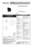
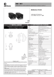
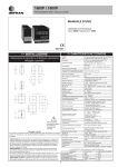
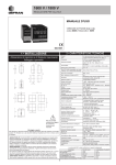
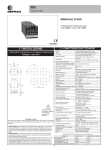
400 / 401
SINGLE DISPLAY TEMPERATURE CONTROLLER WITH UNIVERSAL INPUT
USER’S MANUAL
SOFTWARE VERSION 3.0x
code 81500D / edition 12 - 05/04
2 • TECHNICAL SPECIFICATIONS
1 • INSTALLATION
Display
• Dimensions and cut-out: Panel mounting
63
4 mechanical keys (Man/Aut, Raise, Lower, F)
Accuracy
0.25% f.s. at 25°C ambient temperature
Main input
TC, RTD (Pt100), PTC
60mV, 10V, Ri ≥ 1MΩ; 20mA, Ri = 50Ω
Thermocouples
IEC 584-1 (J, K, R, S, T, B, E, N)
Cold junction error
0,1° / °C
RTD type (scale configurable within indicated
range, with or without decimal point)
DIN 43760 (Pt100)
70
48
4 digit green LED’s, digit height 10mm
Keys
48
70
45
45
99
10
!
For correct and safe
installation, follow the
instructions and observe
the warnings contained in
this manual.
Panel mounting:
Fix the device with the bracket provided before making any electrical connections.
To mount two or more devices side by side, use the cut-out dimensions shown above.
CE MARKING: EMC (electromagnetic compatibility) conformity to EEC Directive
89/336/CEE with reference to the generic Standard EN61000-6-2 (immunity in
industrial environments) and EN50081-1 (emission in residential environments). BT
(low voltage) conformity to Directive 73/23/CEE as modified by Directive 93/68.
MAINTENANCE: Repairs must be done out only by trained and specialized personnel.
Cut power to the device before accessing internal parts.
Do not clean the case with hydrocarbon-based solvents (Petrol, Trichlorethylene, etc.).
Use of these solvents can reduce the mechanical reliability of the device. Use a cloth
dampened in ethyl alcohol or water to clean the external plastic case.
SERVICE: GEFRAN has a service department. The warranty excludes defects caused
by any use not conforming to these instructions.
Max. RTD line resistance
20Ω
PTC type (on request)
990Ω, 25°C
Safety
detection of short circuit or opening of sensors,
LBA alarm
°C / °F selection
Linear scale ranges
Control actions
pb
dt
di
Action
Control outputs
Limitation Max power heat / cool
Cycle time
Faceplate configurable
-1999 to 9999 configurable decimal point position
Pid, Autotune, on-off
0,0...999,9 %
0,00...99,99 min
0,00...99,99 min
heat or cool
on / off, pwm
0,0...100,0 %
0...200 sec
Type of main output
relay, logic
Softstart
0,0...500,0 min
Fault power setting
-100,0...100,0 %
Power off function
Maintains PV display; can be excluded
Configurable alarms
Up to 3 alarm functions assignable to an output
and configurable as: maximum, minimum,
symmetrical, absolute/relative, LBA
Alarm masking
exclude on power-up
Relay contact
NO (NC), 5A, 250V cosϕ=1
Logic output for static relays
10Vdc, Rout = 100Ω (6V/20mA),4V/20mA x OUT3
Optional current transformer input
(Mod. 401)
T.A. 50mAac, 50/60Hz, Ri = 2Ω
Power supply
(standard) 100...127Vac (220...240vac) ± 10%
(optional) 11...14Vac (22...27Vac) ± 10%
(optional) 11...27Vac/dc (not isolated)
50/60Hz, 5.5 VA max.
Faceplate protection
IP65
Working / Storage temperatures
0...50°C / -20...70°C
Relative humidity
20 to 85%, non-condensing
Environmental conditions of use
for internal use only, altitude up to 2000m
Installation
Panel mounting, extractable from front
Weight
210g for the complete version
EMC conformity has been tested with the following connections
FUNCTION
TC input probe
“PT100” input probe
Power supply cable
Relay output cables
Current transformer cables
10
CABLE
0,8 mm2 compensated
1 mm2
1 mm2
1 mm2
1,5 mm2
LENGTH USED
5m
3m
1m
3,5 m
3,5 m
Short Operating Instruction
for temperature regulator 400
We deliver our temperature regulator in its basic adjustment for the control of heaters. For other applications, the
parameters should be accordingly modified with the help of the attached operating instruction.
1.
Link: There is a link for the thermocouple (NiCr Ni, type K) on the front plate. Laterally, heaters can be
steered through the automatic controller. The permissible power for each power connection amounts to 5 A
with 230 ~V. Attention the output is only for resistive load!
2.
Display: The temperature (actual value) measured at the thermocouple is displayed. Heater switching
impulses (220 V at the plug sockets) are displayed by a red LED down/up OUT 2. If the actual value is
below the set point, this is displayed by a red LED arrow directing to the left (LOW); if the actual value
exceeds the set point, this is indicated by a red LED arrow directing right (HIGH) OUT 2 turn off; no 220 V
at the plug sockets). If the actual value is within the range of tolerance of the set point, a green beam-LED
lights up.
3.
Temperature adjustment: Through pressing key >F< on the front plate „-SP“ appears, alternating with the
set point actually given. With the arrow keys > v / ^ < the desired set point can be set. After the
modification press key >F< again to transfer the new set point (display: > AL.1<). After 5 seconds the
instrument switches back into the initial state and the modified set point is taken over. If the desired value is
modified and there is no acknowledgement by key >F< after 5 seconds, the instrument again switches back
into the initial state, but the set point is reduced to the lower alarm value. By pressing key >F< second time
(next of the set point), further values such as alarm value 1 and 2 (optionally) and the placing degrees (not
by automatic, only by manual) can be called up. Note: if key >F< is initially pressed longer than 2 seconds,
you achieve a level on which there is the danger of an unintentional change of the functional parameters.
4.
Temperature control: Thermocouple NiCr Ni type K, without self-optimization and auto optimization,
proportional temperature control, with soft start function (note: heating regulates the full heating power after
approximately 3-5 minutes; in any case soft start for the protection of the heating cartridge).
Important adjustments for modifications of the temperature control:
Blocked: Pass: 99 (protection: 28)
by parameter CFG (press >F< key for 2 seconds, press twice afterwards, CFG appears)
S.tu: Adjustment whether working with optimization (see instruction)
h.Pb: Value of heating in proportion to the final value of the thermocouple; i.e. the regulation starts 1 % of
the thermocouple’s final value below the set point. Example: adjustment: 1,0, thermocouple type K: 1300°C
= 1 % = 13 °C, set point: 500 °C; this means that the temperature control is started at 487°C.
h.It: the smaller the value, the more an adaptation value to the set point is attempted. If the value is small,
there is the danger of over swing.
h.dt: the larger the value, the more an over swing is prevented; this affects a dampening of the controlling
action. The relation of the values h.It to h.dt should always be 4:1.
5.
Manual regulation: Through pressing key > O < you can choose between automatic and manual operation.
In case of manual operation the instrument is only used as a momentum generator and there is no need for a
thermocouple (important when sensor breaks). After reversing, all LED light up and the position can be
chosen. Value 100 means constant heating, value 50 means that the processes of turning on and turning off
take equally long. The clock speed is entered. A set point is not considered. The temperature and the set
value are displayed alternately. Change over to the automatic mode by pressing key > O <.
6.
Turning on/Turning off: The instrument can be turned on and off by plucking in the power supply plug or
pulling it off. Furthermore, there is the possibility of turning the instrument off while it is connected with the
voltage supply. Therefore, key >F< and key > ^ < have to be pressed at the same time and for 5 seconds.
After turning the instrument off, only a decimal point can be seen. The instrument is turned on by pressing
key >F< for 5 seconds.
7.
Alarm outputs: Optionally the instrument can also be delivered with a socket for alarm outputs. The contact
is closed by alarm (alarm 1, 2 and sensor breaks).
8.
A fuse is installed inside as protection, if the current is more than 5 amperes. Attention: The relay can
switch only resistive load (ohm-resistance)! Don’t regulate transformer and systems with more as 5
amperes. Working temperature: -10 to +40°C
We recommend the adjustment with auto- and self-optimization respectively; for further information please see
attached instruction.
Paul-Gothe-GmbH V.45/05/NCN
t regler-nicrni-3.doc
Paul Gothe GmbH
Temperaturregler - Schutz vor Verstellen der Parameter
Temperature controller – Protection against manipulation of the parameters
Deutsch:
Der Temperaturregler kann mit einer einfachen Einstellung vor ungewolltes Verstellen der
Parameter geschützt werden.
Den Schutz stellen Sie wie folgt ein:
Die F-Taste solange drücken bis „PAS“ erscheint. Mit den Auf- und Ab – Tasten die Zahl 99
einstellen, anschließend die Taste F drücken bis „Pro“ erscheint. Jetzt die Zahl 28 einstellen.
Nach erneutem langen Drücken der F-Taste wird das Menü verlassen und der Schutz ist
aktiviert.
Desaktivieren des Schutzes:
Die F-Taste solange drücken bis „PAS“ erscheint. Mit den Auf- und Ab – Tasten die Zahl 99
einstellen, anschließend die Taste F drücken bis „Pro“ erscheint. Jetzt die Zahl 00 einstellen.
Nach erneutem langen Drücken der F-Taste wird das Menü verlassen und der Schutz ist
desaktiviert.
Anzeige der Heizintervalle
Anzeige
Anzeige Regelabweichung
Auto/Manuell
Funktionstaste
Auf und Ab Tasten
English:
The temperature controller can be protected against inadvertent manipulation of the
parameters with a simple change of the parameter.
You activate the protection like follows:
Press the F-key as long as „PAS“ appears. With the up and down key type the number 99,
afterwards press F key until „Pro“ appears. Type there the number 28.
After renewed long pressing of the F-key, the menu is left and the protection is activated.
To deactivate the protection:
Press the F-key as long as „PAS “appears. With the up and down key type the number 99,
afterwards press F key until „Pro“ appears. Type there the number 00.
After renewed long pressing of the F-key, the menu is left and the protection is deactivated.
• Beim Anschließen des Gerätes sind die in der Bedienungsanleitung enthaltenen Anweisungen
sorgfältig zu befolgen.
• Das Gerät verfügt über KEINEN EIN/AUS - Schalter und wird daher unmittelbar nach dem Anschluß
an die Betriebsspannung aktiviert.
Die Firma PAUL GOTHE übernimmt in keinem Fall die Haftung für Sach- oder Personenschäden, die
auf unbefugte Eingriffe, sowie unsachgemäße oder den technischen Eigenschaften des Gerätes nicht
angemessene Bedienung oder Anwendung zurückzuführen sind.
Paul Gothe GmbH Wittener Str. 82, D-44789 Bochum, phone: ++49-234 - 33 51 80, www.paulgothe.com
3 • DESCRIPTION OF FACEPLATE
Indication of output states
OUT 1 (Main); OUT 2 (AL1); OUT 3 (AL2)
LED flashes during software shutdown
Deviation indicator
On if deviation is <0.25% f.s.
Display
Displays process variable, set point and
configuration parameters
Deviation indicator
On if deviation is between 0.25 and 5% f.s.
Flashes if deviation is >5% f.s.
LED on during Self-tuning or Softstart;
LED flashes during Auto-tuning
Function key
Gives access to different configuration stages ••
Confirms any parameter changes
Automatic/Manual setting selection
In Manual, corresponds to flashing of deviation
indicator
“Raise” and “Lower” keys:
These keys are used for any operation that requires a numerical parameter to be raised or lowered. ••The speed of change is
proportional to the time the key is pressed. •• The operation is not cyclic: once the maximum (minimum) limit is reached, there will be no
further increase (decrease) of the value, even if the key remains pressed.
4 • CONNECTIONS
TOP
• Current transformer outputs / inputs
Out2 (Al1)
19
+
20
Out1 (Main)
21
+
22
Out3 (Al2)
Ing. T.A.
+
6
Generic user-configurable
output
- relay 5A/250Vac
- logic 10V, (20mA/6V)
Rout=100Ω
- relay 5A/250Vac
- logic 5V,Rout=22Ω (4V/20mA)
Current transformer
50mAac, 2Ω 50/60Hz
5
24
7
6
20
17
8
5
21
16
9
4
2
22
15
10
3
1
23
14
11
2
24
13
12
1
Optional
11...14Vac (22...27Vac) ±10%
11...27Vac/dc (not isolated)
!
Use wires of
adequate thickness
(min. 1mm2)
PT100, PTC
4
dc voltage
linear input
0...60mV, 0...10V,
12...60mV, 2...10V
• PTC / Pt100 2-3 wires
3
2
T
1
Max. power 5.5VA; 50/60Hz
-
+
• Linear (V)
2
-
1
+
T
Available thermocouples:
J, K, R, S, T, B, E, N
- Respect polarities
- For extensions, use
compensated cable
appropriate for
thermocouple.
• TC
2
1
Pt100 3 wires PTC / Pt100 2 wires
-
+
Device structure: identification of boards
CPU BOARD (Sealing Side)
S6 = ON Enable Calibration
S2, S3 (LS) = Selection of contacts
NO, NC for Out1/Out2
S4
S3
VH
S1, S4 = Selection of Power Range
S2
!
Jumpers
on Sealing
Side
K2
S3
2NO
2NC
S9
S2
K1
S4S1
1NO
TRANSFORMER
1NC
J9
S6
POWER SUPPLY
11
(Components Side)
S1
220...240Vac
(22...27Vac)
100...127Vac
(11...14Vac)
VL
S4
S5
S6
S7
~
18
S1
PWR
Standard:
100...127Vac (220...240Vac) ±10%
TX
RX
GND
23
• Linear (I)
19
only for mod. 401
• Power supply
~
• Inputs
dc current
linear input
0 ... 20mA, 4 ... 20mA
5 • Standard Configuration Menu
CFG
Setting Parameters
Configurat.
Default Custom
S.tu Autotuning Selftuning Softstart
continuous
0
NO
NO
NO
1
YES
NO
NO
2
NO
YES
NO
3
YES
YES
NO
4
NO
NO
YES
0
4
Enable
selftuning,
autotuning,
softstart
10.0
1
Proportional heating
range or hysteresis in
regulation ON/OFF
0 ... 999,9% f.s.
4.0
4
Integral heating time
0,00 ... 99,99 min
1.0
1
Derived heating time
0,00 ... 99,99 min
100.0
100
Maximum limit heating
power
0,0 ... 100,0%
-1
-1
Hysteresis for alarm 1
± 999
scale points
InP
Input settings
Configurat.
Default Custom
See table on InP
menu
Control type
[0...11]
22
3
0
2
Type of sensor, signal
and main input scale
0
0
Position of decimal point
for main input scale
0
0
Minimum limit of main
input scale
min...max of input
selected in tyP
Maximum limit of main
input scale
min...max of input selected
in tyP
1000
1000
Out
See table on InP
menu
dP.S
0
1
2
3
Format
xxxx
xxx.x
xx.xx (*)
x.xxx (*)
Output settings
Configurat.
Default Custom
0
0
See table on Out
menu
Alarm type 1
0
0
OUT 1
Attribution of
reference signal:
HEAT, COOL,
AL1, AL2, AL3
2
0
OUT 2
Attribution of
reference signal:
HEAT, COOL,
AL1, AL2, AL3
r.o.x
0
1
2
3
4
5
6
7
8
9
10
MAIN logic output function, relay (OUT1)
HEAT (heating control output)
COOL (cooling control output)
AL1 - alarm 1
AL2 - alarm 2
AL3 - alarm 3 [A.Hb mod. 401])
LBA - alarm LBA
(AL1) OR (AL2)
(AL1) OR (AL2) OR (AL3 [A.Hb mod. 401])
(AL1) AND (AL2)
(AL1) AND (AL2) AND (AL3 [A.Hb mod. 401])
+ 16 for logic level denied at output
10
30
Cycle time OUT1 relay or
logic = HEAT or COOL
12
0. ... 200 sec
6 • PROGRAMMING and CONFIGURATION
F
LEVEL 1 DISPLAY
P.V.
Pressed for
approx.
2 sec.
Process variable (display PV)
UPd
Software version
CFG
Setting parameters
InP
Input settings
Release the F key
to select the
displayed menu
Out
Output settings
Press the F key to
access the
parameters
PASS
Password
Keep the F key
pressed to exit any
menu
Keep the F key
pressed to scroll
the menus
Setpoint variable
1
C.T.
Current transformer input variable
(*)
Alarm threshold 1
Alarm threshold 2
NO
Alarm threshold 3
Keep F + Auto/Man
keys pressed for 2
sec. on any menu
to go immediately
to level 1 display
PASS = 99
YES
Alarm HB limit (scale points current mod. 401
transformer input)
(Displayed if a value >3 in Al.n is set)
mod. 401
Prot
NO
Setting output values
(+Heat / -Cool)
(*)
Protection code
28
Pressing the
Auto/Man + F keys
on any menu
immediately returns
you to the previous
parameter.
PASS = 199
YES
7
NO
(*) Timed return to PV disabled
If the Inc, Dec, F keys are not pressed within 15 sec.,
the display returns to the P.V. value
S6 = ON
YES
_CAL
Select calibration menu [ 0...6 ]
Select calibration menu [ 0...7 ]
mod. 401
NB: Parameters not required for a particular configuration are not displayed
• CFG
CFG
Setting parameters
Configurat.
Default Custom
0
4
Enable
selftuning,
autotuning,
softstart
S.tu Autotuning Selftuning Softstart
continuous
0
NO
NO
NO
1
YES
NO
NO
2
NO
YES
NO
3
YES
YES
NO
4
NO
NO
YES
4.0
1
4
Proportional heating
range or hysteresis in
ON/OFF
0 ... 999,9% f.s.
Integral heating time
0,00 ... 99,99 min
Manual reset
-999 ... 999
scale points
0
Reset power
-100,0 ... 100,0%
10
N.B. S.tu functions are cancelled when switching to MAN.
10.0
0
-1
-1
1.0
1
Derived heating time
0,00 ... 99,99 min
-1
100.0
Maximum limit heating
power
0,0 ... 100,0%
Cooling setpoint relative
to heating set
-999 ... 999
scale points
Proportional cooling
range or hysteresis in
ON/OFF
0 ... 999,9% f.s.
4
Integral cooling time
0,00 ... 99,99 min
1
Derived cooling time
0,00 ... 99,99 min
Maximum limit cooling
power
0,0 ... 100,0%
100
0
10
Softstart time
0,0 ... 500,0 min
Hysteresis for alarm 1
± 999
scale points
Hysteresis for alarm 2
± 999
scale points
Hysteresis for alarm 3
± 999
scale points
Delay for tripping of Hb
alarm
0
25
0
Wait time for tripping
of LBA alarm
(setting 0 disables LBA alarm)
Limit of power supplied
under LBA alarm
conditions
Fault Action power
(supplied in case of sensor
fault)
mod. 401
0,0...500,0 min
(*)
-100,0 ... 100,0%
c.on / OFF / h.on (*)
-100,0 ... 100,0%
c.on / OFF / h.on
(*) If the LBA alarm is active (display flashing alternately with 4 decimal points),
you can cancel it by pressing keys ∆ + ∇ when OutP is seen, or by switching
to Manual.
100
0...999 sec
N.B.: the LBA alarm is excluded for ON/OFF controls
13
• InP
InP
Digital filter
on main input
0,1
Input settings
0,0 ... 20,0 sec
Configurat.
Default Custom
22
Type of control
[0...91]
3
+16 disable parameters
CFG: rst, PrE, SoF, Lbt, Lbp, FAP,
HY.2, HY.3 (only for model 400)
InP: FLt, FLd, oFS, LoL, HIL
Out: ALn, A2t, A3t (only for model 400), rEL
FLt, FLd, oFS stay at set value.
ALn is forced to 1 (only for mod. 400)
All other parameters are considered 0.
CtrL
0
1
2
3
4
5
6
7
8
9
10
11
Type of control
P hot
P cold
P hot / cold
PI hot
PI cold
PI hot / cold
PID hot
PID cold
PID hot / cold
ON-OFF hot
ON-OFF cold
ON-OFF hot / cold
0
2
Decimal point position for
main input scale
0
0 ... 9,9
scale points
dP.S
0
1
2
3
Format
xxxx
xxx.x
xx.xx (*)
x.xxx (*)
(*) not available for
TC, RTD, PTC scales
0
Default: derived action sample time = 1 sec
+32: derived action sample time = 8sec
+64: derived action sample time = 240msec with derived action filter assigned
to Flt parameter (time filter)
0
Digital filter on display of
process variable; acts as
hysteresis
0,5
1000
0
1000
Minimum limit of main
input scale
min…max scale of input
selected in tyP
Maximum limit of main
input scale
min…max scale of input
selected in tyP
Type of probe, signal and scale of main input
0
SENSOR: TC
Scale
Max. scale range
(C/F) without decimal point
J (Fe-CuNi)
C
0 / 1000
J (Fe-CuNi)
F
32 / 1832
K (NiCr-Ni)
C
0 / 1300
K (NiCr-Ni)
F
32 / 2372
R (Pt13Rh - Pt)
C
0 / 1750
R (Pt13Rh - Pt)
F
32 / 3182
S (Pt10Rh - Pt)
C
0 / 1750
S (Pt10Rh - Pt)
F
32 / 3182
T (Cu-CuNi)
C
-200 / 400
T (Cu-CuNi)
F
-328 / 752
B (Pt30Rh - Pt6Rh) C
44 / 1800
B (Pt30Rh - Pt6Rh) F
111 / 3272
E (NiCr-CuNi)
C
-100 / 750
E (NiCr-CuNi)
F
-148 / 1382
N (NiCrSi-NiSi)
C
0 / 1300
N (NiCrSi-NiSi)
F
32 / 2372
SENSOR: RTD 3 wires
tYP
16
17
Max. scale range
with decimal point
0,0 / 999,9
32,0 / 999,9
0,0 / 999,9
32,0 / 999,9
0,0 / 999,9
32,0 / 999,9
0,0 / 999,9
32,0 / 999,9
-199,9 / 400,0
-199,9 / 752,0
44,0 / 999,9
111,0 / 999,9
-100,0 / 750,0
-148,0 / 999,9
0,0 / 999,9
32,0 / 999,9
6
1000
18
19
Type of probe
PTC
PTC
Max. scale range
without decimal point
-200 / 850
-328 / 1562
Signal type
0...60mV
12...60mV
Scale
(C/F)
C
F
Max. scale range
without decimal point
-55 / 120
-67 / 248
Signal type
0...20mA
4...20mA
Scale
linear
linear
Signal type
0...10V
2...10V
Max. scale range
with decimal point
-199,9 / 850,0
-199,9 / 999,9
Scale
linear
linear
Scale
linear
linear
SENSORE TA: CORRENTE 50mAac
Max. non-linearity error
for thermocouples (TC),
resistors (PT100) and
thermistors (PTC).
The error is calculated
as deviation from
theoretical value and is
expressed as
percentage of full scale
(in °C
Upper limit for local setpoint
and absolute alarms
Lo.S ... Hi.S
Output settings
Configurat.
Default Custom
Max. scale range
with decimal point
-55.0 / 120.0
-67.0 / 248.0
Number of alarms
mod. 400
mod. 401
0 ... 3
0 ... 6
4, 5, 6 to select HB alarm as alternative to alarm 3
AL.x
0
(CAL = 5)
Scale
linear
0
Alarm
type 1
0
1
2
3
4
5
6
7
0
Alarm
type 2
0
Alarm
type 3
Max. scale range
-1999 / 9999
-1999 / 9999
(CAL = 6)
Max. range scala
-1999 / 9999
-1999 / 9999
Direct
(maximum)
Inverse
(minimum)
direct
inverse
direct
inverse
direct
inverse
direct
inverse
Absolute
Relative
to active
setpoint
absolute
absolute
relativo
relativo
absolute
absolute
relativo
relativo
Normal
Symmetrical
(window)
normal
normal
normal
normal
symmetrical
symmetrical
symmetrical
symmetrical
+ 8 to disable on power-up until first alarm
Function of
HB alarm
mod. 401
Hb_F Description
0
Relay, logic output: alarm active
with load current value below
limit set in ON time
of control output
1
Relay, logic output: alarm active
with load current value above
limit set in OFF time
of control output
2
Alarm active if one of functions 0 and 1
is active (OR logic for functions 0 and 1) (*)
3
Alarm HB continuous heating (**)
7
Alarm HB continuous cooling (**)
With mod. 401, set CAL=7 to calibrate the current transformer input
Signal type
0 ... 50mAac
Lo.S ... Hi.S
Max. scale range
-1999 / 9999
-1999 / 9999
SENSOR: VOLTAGE 10V or TRANSMITTER
tYP
24
25
Lower limit for local setpoint
and absolute alarms
Out
(CAL = 4)
SENSOR: CURRENT 20mA or TRANSMITTER
tYP
22
23
mod. 401
(CAL = 3)
SENSOR: VOLTAGE 60Mv
tYP
20
21
0,0...99,9
• Out
2
tYP
Max. current transformer
input scale
(CAL = 2)
Type of probe Scale
(C/F)
PT100
C
PT100
F
SENSOR PTC
-999 ... 999
scale points
(CAL = 1)
tYP Type of probe
0
1
2
3
4
5
6
7
8
9
10
11
12
13
14
15
Main input offset
correction
(CAL = 7)
Max. range scala
0 ... 99,9
S, R range 0...1750°C; error < 0.2% f.s. (t > 300°C) /
for other range; error < 0.5% f.s.
T
error < 0.2% f.s. (t > -150°C)
B
range 44...1800°C; error < 0.5% f.s. (t > 300°C) /
range 44,0...999,9; error < 1% f.s. (t > 300°C)
+0 assigned to OUT1 (only for Hb_F = 0, 1, 2)
+4 assigned to OUT2 (only for Hb_F = 0, 1, 2)
+16 alarm HB reverse
error < 0,2% f.s.
Tc: J, K, E, N,
PTC
error < 0,2% f.s.
PT100 scale -200...850°C
Precision better than 0,2% f.s. at 25°C
(*) minimum limit is set = 12.5% of current transformer f.s.
(**) As type 0 without reference to cycle time .
14
0
2
OUT 1
Attribution of reference
signal: HEAT, COOL, AL1,
AL2, AL3
0
OUT 2
Attribution of reference
signal: HEAT, COOL, AL1,
AL2, AL3
0
OUT 3
Attribution of reference
signal: HEAT, COOL, AL1,
AL2, AL3
0
mod. 401
10
30
30
MAIN logic output function, relay (OUT1)
HEAT (heating control output)
COOL (cooling control output)
AL1 - alarm 1
AL2 - alarm 2
AL3 - alarm 3 [A.Hb mod. 401])
LBA - alarm LBA
(AL1) OR (AL2)
(AL1) OR (AL2) OR (AL3 [A.Hb mod. 401])
(AL1) AND (AL2)
(AL1) AND (AL2) AND (AL3 [A.Hb mod. 401])
+ 16 for logic level denied at output
N.B. When T.A. input is present, Out3
(if configured) is limited to indication of
corresponding LED.
Cycle time OUT1 relay or
logic = HEAT or COOL
1. ... 200 sec
Cycle time OUT2 relay or
logic = HEAT or COOL
1. ... 200 sec
Cycle time OUT3 relay or
logic = HEAT or COOL
1. ... 200 sec
rEL
Fault action
(definition of state
in case of broken
sensor) alarms
AL1, AL2, AL3.
Select intrinsic
safety.
1
r.o.x
0
1
2
3
4
5
6
7
8
9
10
0
1
2
3
4
5
6
7
Alarm
1
OFF
ON
OFF
ON
OFF
ON
OFF
ON
Alarm
2
OFF
OFF
ON
ON
OFF
OFF
ON
ON
mod. 401
Alarm
3
OFF
OFF
OFF
OFF
ON
ON
ON
ON
1) In case of broken sensor, the logic state of the alarm assumes the logic value selected without consideration of
alarm type (direct or reverse): ON = alarm active, OFF = alarm inactive.
2) Alarms are assigned to available outputs by setting codes r.o.1, r.o.2, r.o.3.
• Prot
Pro
Protection code
Pro
0
1
2
3
Display
SP, alarms, OutP
SP, alarms, OutP
SP
SP
99
protection: 28
Change
SP, alarms
SP
SP
+4 disables InP, Out
+8 disables CFG
+16 disables “SW turn on - turn off”
+32 disables MAN/AUTO key
+ 64 to disable manual power modification
To activate the turn off SW function, press keys F
F + ∆ for 5 secs. in P.V.
To return to normal functioning, press key F for 5
secs.
FUNCTION OF HB ALARM (only for mod. 401)
This type of alarm is conditioned by use of the current transformer input. (T.A.)
It signals variations of load absorption by discriminating the level of current at the transformer input in the range (0...HI.A). It is
enabled with configuration code (AL.n); in this case the alarm trip value is expressed in HB scale points.
Select the type of functioning and the assigned control output by means of code Hb.F (“Out” phase).
The alarm limit setting is A.Hb.
The direct HB alarm trips if the value of the current transformer input is below the set limit for Hb.t seconds inclusive of “ON”
time of the selected output.
The HB alarm can be activated only with ON times longer than 0.4 seconds.
HB alarm function also includes control of load current in the OFF interval of the cycle time for the selected output: the HB
alarm will trip if the measured current exceeds approximately 12.5% of the full scale set (parameter HI.A in InP) for Hb.t
seconds inclusive of the OFF state of the output.
The alarm is reset automatically if the cause of the alarm is eliminated.
Setting a limit of A.Hb = 0 disables both types of HB alarms, with de-energizing of the assigned relay.
Indication of load current is displayed by selecting term C.T. (level 1).
NOTE: ON/OFF times refer to the cycle time set for the selected output.
Alarm Hb_F = 3 (7) continuous is active for a load current value below the set limit; it is disabled if the value of the
heating(cooling) output is less than 2%.
15
7 • ACCESSORIES
• Current transformer
1
These transformers are used to measure currents of 50 ÷ 60Hz from 25A to 600A
(nominal primary current). The peculiar characteristic of these transformers is the high
number of secondary turns. This provides a very low secondary current, suitable for an
electronic measurement circuit. The secondary current may be detected as voltage on a
resistor.
2
152050 9640
CODE
Ip / Is
50 / 0.05 A
27
2
5,5
n
OUTPUTS
Ru
Vu
ACCURACY
TA/152 025
25 / 0.05A
0.16 mm
n1-2 = 500
1-2
40 Ω
2 Vac
2.0 %
TA/152 050
50 / 0.05A
0.18 mm
n1-2 = 1000
1-2
80 Ω
4 Vac
1.0 %
9
5,5
Ø Secondary
Wire
30
1
4
2
13
48
In
• ORDER CODE
8
1
10
20
10
19
4
IN = 50Aac
OUT = 50mAac
IN = 25Aac
COD. 330201
OUT = 50mAac
COD. 330200
8
38
20
Hole for 2.9 x 9 selfthreading screws
• RS232 / TTL interface cable for configuration of GEFRAN instruments
N.B.: The RS232 interface for configuration from PC is supplied along with the programming software.
Connect with the instrument powered and with inputs and outputs not connected.
• ORDER CODE
COD. WSK- 0 - 0 - 0
16
Interface Cable + CD
Winstrum
ORDER CODE
400/401
MODEL
Single-display controller
400
Single-display controller with
auxiliary input for current
transformer or output 3
401
OUTPUT 1
Relay
R
Logic
D
OUTPUT 2
Relay
R
Logic
D
OUTPUT 3 / TA INPUT (only for mod. 401)
Relay
R
Logic
D
TA input 50mAac
H
POWER SUPPLY
11...14Vac, (22...27Vac)
0
100...127Vac, (220...240Vac)
1
11...27Vac/dc (not isolated)
9
Please, contact GEFRAN sales people for the codes availability.
• WARNINGS
!
WARNING: this symbol indicates danger.
It is seen near the power supply circuit and near high-voltage relay contacts.
Read the following warnings before installing, connecting or using the device:
• follow instructions precisely when connecting the device.
• always use cables that are suitable for the voltage and current levels indicated in the technical specifications.
• the device has no ON/OFF switch: it switches on immediately when power is turned on. For safety reasons, devices permanently connected to the power
supply require a two-phase disconnecting switch with proper marking. Such switch must be located near the device and must be easily reachable by the
user. A single switch can control several units.
• if the device is connected to electrically NON-ISOLATED equipment (e.g. thermocouples), a grounding wire must be applied to assure that this
connection is not made directly through the machine structure.
• if the device is used in applications where there is risk of injury to persons and/or damage to machines or materials, it MUST be used with auxiliary alarm
units. You should be able to check the correct operation of such units during normal operation of the device.
• before using the device, the user must check that all device parameters are correctly set in order to avoid injury to persons and/or damage to property.
• the device must NOT be used in inflammable or explosive environments. It may be connected to units operating in such environments only by means of
suitable interfaces in conformity to local safety regulations.
• the device contains components that are sensitive to static electrical discharges. Therefore, take appropriate precautions when handling electronic circuit
boards in order to prevent permanent damage to these components.
Installation: installation category II, pollution level 2, double isolation
• power supply lines must be separated from device input and output lines; always check that the supply voltage matches the voltage indicated on the
device label.
• install the instrumentation separately from the relays and power switching devices
• do not install high-power remote switches, contactors, relays, thyristor power units (particularly if “phase angle” type), motors, etc... in the same cabinet.
• avoid dust, humidity, corrosive gases and heat sources.
• do not close the ventilation holes; working temperature must be in the range of 0...50°C.
If the device has faston terminals, they must be protected and isolated; if the device has screw terminals, wires should be attached at least in pairs.
• Power: supplied from a disconnecting switch with fuse for the device section; path of wires from switch to devices should be as straight as possible; the
same supply should not be used to power relays, contactors, solenoid valves, etc.; if the voltage waveform is strongly distorted by thyristor switching units
or by electric motors, it is recommended that an isolation transformer be used only for the devices, connecting the screen to ground; it is important for the
electrical system to have a good ground connection; voltage between neutral and ground must not exceed 1V and resistance must be less than 6Ohm; if
the supply voltage is highly variable, use a voltage stabilizer for the device; use line filters in the vicinity of high frequency generators or arc welders;
power supply lines must be separated from device input and output lines; always check that the supply voltage matches the voltage indicated on the
device label.
• Input and output connections: external connected circuits must have double insulation; to connect analog inputs (TC, RTD) you have to: physically
separate input wiring from power supply wiring, from output wiring, and from power connections; use twisted and screened cables, with screen connected
to ground at only one point; to connect adjustment and alarm outputs (contactors, solenoid valves, motors, fans, etc.), install RC groups (resistor and
capacitor in series) in parallel with inductive loads that work in AC (Note: all capacitors must conform to VDE standards (class x2) and support at least 220
VAC. Resistors must be at least 2W); fit a 1N4007 diode in parallel with the coil of inductive loads that operate in DC.
GEFRAN spa will not be held liable for any injury to persons and/or damage to property deriving from tampering, from any incorrect or
erroneous use, or from any use not conforming to the device specifications.
17
• CONTROL ACTIONS
Proportional Action:
action in which contribution to output is proportional to deviation at input (deviation = difference between controlled variable and setpoint).
Derivative Action:
action in which contribution to output is proportional to rate of variation input deviation.
Integral Action:
action in which contribution to output is proportional to integral of time of input deviation.
Influence of Proportional, Derivative and Integral actions on response of process under control
* An increase in P.B. reduces oscillations but increases deviation.
* A reduction in P.B. reduces the deviation but provokes oscillations of the controlled variable (the system tends to be unstable if P.B. value is
too low).
* An increase in Derivative Action corresponds to an increase in Derivative Time, reduces deviation and prevents oscillation up to a critical
value of Derivative Time, beyond which deviation increases and prolonged oscillations occur.
* An increase in Integral Action corresponds to a reduction in Integral Time, and tends to eliminate deviation between the controlled variable
and the setpoint when the system is running at rated speed.
If the Integral Time value is too long (Weak integral action), deviation between the controlled variable and the setpoint may persist.
Contact GEFRAN for more information on control actions.
• MANUAL TUNING
A) Enter the setpoint at its working value.
B) Set the proportional band at 0.1% (with on-off type setting).
C) Switch to automatic and observe the behavior of the variable. It will be similar to that in the figure:
Process
Variable
D) The PID parameters are calculated s follows: Proportional band
Peak
P.B.= ---------------------------------------- x 100
(V max - V min)
T
Peak
Time
(V max - V min) is the scale range.
Integral time: It = 1.5 x T
Derivative time: dt = It/4
E) Switch the unit to manual, set the calculated parameters. Return to PID action by setting
the appropriate relay output cycle time, and switch back to Automatic.
F) If possible, to optimize parameters, change the setpoint and check temporary response.
If an oscillation persists, increase the proportional band. If the response is too slow, reduce
it.
1
• SELF-TUNING
The function works for single output systems (heating or cooling). The self-tuning action calculates optimum control parameter values during
process startup. The variable (for example, temperature) must be that assumed at zero power (room temperature).
The controller supplies maximum power until an intermediate value between starting value and setpoint is reached, after which it zeros power.
PID parameters are calculated by measuring overshoot and the time needed to reach peak.
When calculations are finished, the system
Process
disables automatically and the control proceeds until the setpoint is reached.
Variable
S.P.
How to activate self-tuning:
A. Activation at power-on
1. Set the setpoint to the required value
2. Enable selftuning by setting the Stun parameter to 2 (CFG menu)
3. Turn off the instrument
4. Make sure the temperature is near room temperature
5. Turn on the instrument again
Peak
S.P. + t.a.
2
T
t.a.
Time
)
.
.)
The procedure runs automatically until finished, when the new PID parameters are stored: proportional band, integral and derivative times
calculated for the active action (heating or cooling).
.
When finished, the Stun code is automatically cancelled.
Notes :
-The procedure does not start if the temperature is higher than the setpoint (heating control mode) or if the temperature is lower than the
setpoint (cooling control mode). In this case , the Stu code is not cancelled.
.
• AUTO-TUNING
Enabling the auto-tuning function blocks the PID parameter settings.
It can be one of two types: permanent (continuous) or single-action
(one-shot).
* Continuous auto-tuning is activated via the Stu parameter (values 1,
3, 5). It continuously reads system oscillations, immediately seeking
the PID parameter values that reduce the current oscillation. It does
not engage if the oscillations drop below 1.0% of the proportional
band. It is interrupted if the set-point is changed, and automatically
resumes with a constant set-point. The calculated parameters are not
saved if the instrument is switched off, if the instrument is switched to
manual, or if the configuration code is disabled. The controller
resumes with the parameters programmed before auto-tuning was
enabled.
* One-shot auto-tuning can be enabled manually or automatically. It is
activated via the Stu parameter (as can be seen on the table, the
values to be set depend on whether Self-tuning or Soft-start is
enabled.). It is useful for calculation of PID parameters when the
system is around the set-point. It produces a variation on the control
output at a maximum of ± 100% of the current control power limited by
h.PH - h.PL (hot), c.PH - c.PL (cold), and assesses the effects in timed
overshoot. The calculated parameters are saved.
.
.
.
.
.
.
.
p.
• CONTROLS
PV
PV
SP+cSP
c_Pb
SP
SP+cSP
SP
c_Pb
h_Pb
h_Pb
time
time
+100%
Control output
0%
+100%
Control output
0%
-100%
-100%
Control output with proportional action only if proportional heating band
overlaps proportional cooling band.
PV = Process Value
SP+cSP = cooling setpoint
c_Pb = Proportional cooling band
Control output with proportional action only if proportional heating band
overlaps proportional cooling band.
SP = Heating Setpoint
h_Pb = proportional heating band
2