1
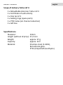
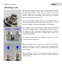
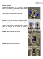
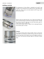
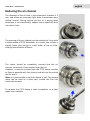
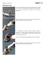
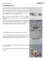
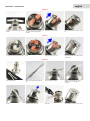
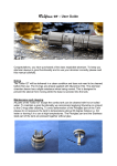
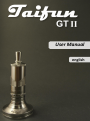
Taifun GT II – Bedienungsanleitung
deutsch
User Manual
english
Taifun GT II – User Manual
english
IMPORTANT
Please read these instructions carefully, before using your
Taifun GT II rebuildable tank atomizer.
Thank you for purchasing a Taifun GT II. With this product you
have purchased a high quality rebuildable tank atomizer, which
has been designed exclusively for use with e-liquid. Before use it
is necessary to install a coil of resistance wire (e.g. NiCr wire)
and a suitable wick (e.g. cotton, silicate fiber) according to the
instructions of this manual.
Furthermore, it is required to fill the atomizer with e-liquid after
coil setup. If you are having trouble making a suitable coil, or if
you have no previous experience with rebuildable atomizers,
please contact your supplier or www.smokerstore.de.
After the attachment of a new coil, the resistance should be
measured. To do this, use a multimeter or a suitable battery
device with resistance measurement. If a short circuit is
detected, the atomizer must never be put into operation. Short
circuits can cause damage to the battery device and/or
batteries. In this case, please correct the coil or make a new
coil.
english
Taifun GT II – User Manual
IMPORTANT
Please use only liquids which explicitly
are intended for use in e-cigarettes.
The Taifun GT II is made of high quality materials and has been
thoroughly cleaned prior to delivery. Cleaning before use is not
necessary. Any visible residues are clean water and glycerine
used for pretreatment of o-rings.
If you want to clean the atomizer after longer use, a short rinse
of all parts under warm water is sufficient.
Please thoroughly dry all parts before assembling the atomizer
again. We also recommend that prior to assembly you moisten
the o-rings with a little liquid or glycerine. This increases the
durability of the o-rings and simplifies the assembly.
If an o-ring or an insulator is damaged, please replace it. The
necessary spare parts are partially included in delivery and can
be reordered via your supplier or www.smokerstore.de.
english
Taifun GT II – User Manual
Scope of delivery Taifun GT II
1 x Rebuildable Atomizer Taifun GT II
1 x Certificate of authenticity
1 x Drip tip GT II
1 x Sealing rings (spare parts)
1 x PTFE tubes (air channel reduction)
1 x Gift box
Specifications
Diameter:
Length (without drip tip):
Weight:
Capacity:
Material:
23mm
57,4 mm
approx. 97 g
approx. 5ml
Stainless steel (1.4301),
Borosilicate glass,
PTFE (Polytetrafluorethylen)
Taifun GT II – User Manual
english
Attaching a coil
On the base there are two screws used to fasten the coil
(positive and negative pole). The coil should be mounted
centrally above the air outlet. Please make sure the coil
doesn’t touch the surrounding metal parts (e.g. chamber
sleeve) to prevent a short circuit.
The wick is guided through the coil, and placed either in
front of the openings of the chamber sleeve, or 0.5 - 1 mm
passed through the opening. (See also: coil examples)
The chamber sleeve is inserted into the base. The already
mounted chamber sleeve is designed for standard coils. In
the optional LC-W 3.2 sleeve the liquid channels are milled
out wider and allow the use of a wider wick, as well as a
stronger liquid flow.
To change it, just pull the chamber sleeve out of the
chamber with a slight twist.
When attaching the coil you may: a) remove the chamber
sleeve by pulling it out with a slight twist to prevent any
damage to the base o-ring or b) lower the chamber sleeve
into the base.
After attaching the coil, the chamber sleeve must be
carefully pulled up again until it clicks into place or lowered
into the base.
Taifun GT II – User Manual
Liquid control
The chamber cap is screwed with 1-2 turns on the chamber
sleeve. When screwing it on is advisable to hold the chamber
sleeve to prevent turning. Otherwise, the attached coil could
move.
The o-ring in the chamber cap seals the chamber.
By further screwing the chamber cap on the chamber sleeve
the opening of the liquid channel will be reduced even more.
The correct position depends on the individual setting of the
mounted coil and the wick material.
Tip: after attaching a new coil you should turn the chamber
cap as far as possible, so that only a small opening is
present. If necessary, this opening can be gradually
increased later.
Example: Liquid control maximally opened.
Example: Liquid control closed maximum.
english
Taifun GT II – User Manual
english
Airflow control
The adjustment of the airflow is supplied via the AFC ring
located on the underside of the base and has two differently
sized slots. There are ten air holes under the AFC-ring in total
(five on each side).
While on the one side the holes 1,3,5,7 and 9 are located, the
holes 2,4,6,8 and 10 are placed on the opposite side. Through
the slots in the AFC ring you can now alternately open or
close another hole on each side.
You have the option either to adjust the air passage between
one and ten open air holes.
Example:
An average airflow with 6 holes opened. Three on the front
and three on the back (not visible in the picture). Or three on
the front and two on the back or one on the back and two in
the front. You may also centrally open all 10 holes on both
sides.
Taifun GT II – User Manual
Reducing the air channel
The diameter of the air hole in the evaporator chamber is 3
mm, and allows an extremely light draw at maximum open
airflow control. During intense pre-fire or a wrong draw
technique, it can theoretically happen that e-liquid will drop
into the air hole.
The opening of the air channel can be reduced to 2 mm with
a sleeve made of PTFE (included). As a result, the airflow is
slightly lower and you get a small width of the air flow,
causing intensification of flavor.
The sleeve should be completely inserted into the air
channel, to prevent it from contact with the coil.
However, it must be ensured that the PTFE sleeve remains
as flush as possible with the channel and will not be pushed
too far into it.
Note: It is also possible to split the sleeve in half. The second
piece can be used as a spare part, should the first half
eventually be worn.
To remove the PTFE sleeve a small screwdriver or a bent
paper clip is suitable.
english
Taifun GT II – User Manual
english
Filling the tank
The tank of the Taifun GT II consists of the tank cover, tank
insert made of borosilicate glass (optional: stainless steel),
and a top cap with the air channel and a drip tip
connection.
When filling the tank, the tank must be upside down. The
liquid can now be poured into the tank.
It is important to ensure that the liquid is filled to
maximum at the level of the sealing ring. Otherwise, if the
atomizer is screwed together, liquid will be pressed into
the evaporator chamber.
In case of overfilling, the liquid passes into the air channel.
When screwing the tank back onto the base, you should
continue to keep the tank upside down.
Taifun GT II – User Manual
Changing the tank
To change the tank insert, the top cap has to be removed
from the tank cover. The tank insert can now be removed
and replaced. After replacing the tank insert, the top cap
must be screwed on again. It is important to ensure that
both o-rings (the one in the tank cover as well as the o-ring
of the top cap) sits correct and seals the tank.
Note: The two o-rings have different sizes (19 / 20mm).
Please note the correct placement of the o-rings (see also:
assembly).
To use the XS-tank set (sold separately), the standard tank
has to be unscrewed and the XS tank has to be screwed on.
It is important to make sure that the top cap of the XS set is
used, because this one includes a shorter air channel.
For individualization, various optional parts are available.
From left to right: glass tank (standard), stainless steel tank
(standard), double-window tank cover, standard tank cover,
XS tank cover, stainless steel tank (XS), glass tank (XS)
A matching drip tip is included. Alternatively, any standard
drip tip can be used.
Note: The displayed Drip Tips are for illustration only and not
included.
english
english
Taifun GT II – User Manual
Adjusting the positive pole
On some devices, it may be necessary to adjust the positive
pole of the Taifun GT II to match the pole of the device.
For this purpose, the screw has to be screwed 1 or 2 turns
with a suitable screwdriver.
english
Taifun GT II – User Manual
Parts
Unit A
Base and evaporation chamber
Unit B
Tank and topcap
A1 Base
A2 3 x 0,5 x 9mm PTFE-sleeve (air channel reduction)
A3 11x1 mm o-ring
A4 17x1,5 mm o-ring
A5 17x1 mm o-ring
A6 Spring
A7 Countersunk screw M2 x 8mm
A8 Screw M2x14mm (minus)
A9 Screw M2x20mm (plus)
A10 AFC Ring
A11 Chamber sleeve
A12 Chamber cap
A13 11x1 mm o-ring
B1 Tank cover
B2 20x1 mm o-ring
B3 Glass insert
B4 4x1 mm o-ring
B5 Topcap
B6 19x1 mm o-ring
B7 Drip tip
B8 5x1,5 mm o-ring
B9 5x1,5 mm o-ring
english
Taifun GT II – User Manual
Assembly of unit A
Pic. 1: The PTFE seal (A2) is inserted into
the base (A1), to reduce the air flow.
This step is optional
Pic. 2: The o-rings (A3, A4, and A5) will be
attached on the base (A1).
Pic. 3: The base (A1) should look like this,
when all o-rings (A3, A4, and A5) are
properly seated.
Pic. 5: The countersunk screw (A7) is
tightened and forms the positive pole.
Pic. 6: Use a small screwdriver to adjust
the countersunk screw (A7)/positive pole.
Pic. 7: The two screws for the negative
Pic. 8: You should now easily tighten the
pole (A8) and the positive pole (A9) can be screws (A8, A9) with your fingers, so that
inserted in the appropriate tubes in the
they cannot fall out.
base (A1).
Pic. 9: The AFC ring (A10) is now pushed
Pic. 10: It is important to make sure that
Pic. 11: Now the chamber sleeve (A11) is
onto the bottom of the base (A1). It will be the AFC ring (A10) is inserted with the air
placed on top of the base (A1).
held there by the o-ring (A16).
slots to the top of the base (A1). Then the
air slots are positioned above the air holes.
Pic. 13: Now you can screw the chamber
cap (A12) to the chamber sleeve (A11).
Pic. 14: Unit A is now ready.
Pic. 4: First, the spring (A6) and then the
countersunk screw (A7) are inserted into
the 510 connection.
Pic. 12: On the chamber cap (A12) an oring (A13) is applied.
english
Taifun GT II – User Manual
Assembly of unit B
Pic. 17: The o-ring (B2) is inserted into the
tank cover (B1) and ensures a good fit
here later for the tank.
Pic. 18: The o-ring (B2) should be as
closely as possible in the recess.
Pic. 19: Now the tank insert (B3) is pushed into
the tank cover (B1).
Pic. 20: The tank insert (B3) can be
pushed only from one side to the tank
cover (B1).
Pic. 21: The o-rings (B4, B6) are attached
on the topcap (B5).
Pic. 22: It is important to make sure that
the o-ring (B6) is not pulled over the
threads of the topcap (B5).
Pic. 23: Above the thread, there is a fine groove
in which the O-Ring (B6) is attached.
Pic. 24: The tank Insert (B3) is fixed by
screwing the tank cover (B1) with the
topcap (B5).
Pic. 25: Unit B is now ready.
Pic. 26: The two units A and B will now be
screwed together. The chimney in the
topcap (B5) seals the chamber cap (A12).
Pic. 27: Finally, the drip tip (B7) with the two orings (B8, B9) is attached.
Pic. 28: The Taifun GT II is now fully
assembled
IMPORTANT
It is recommended that you wet the o-rings with liquid,
while assembling the Taifun GT II.
This allows for easier assembly of individual parts.
english
Taifun GT II – User Manual
The wire sizes and materials mentioned here are only examples. Other heating wires, different number of
turns as well as larger / smaller diameter may be used.
Coil examples
Pic. 1: Make six turns with a 28 gauge NiCr
wire on a winding tool with a diameter of
2.5 mm.
Pic. 2: Before attaching the coil the
evaporator chamber is lowered by slight
pressure, into the base and snaps there
noticeably.
Pic. 3: Attach the wire as centrally as
possible between the two poles. The wire
ends should be at the bottom.
Pic. 4: The wire is placed under the screws.
These are then tightened carefully.
Pic. 5: Align the winding with the winding
tool. Then remove the winding tool.
Pic. 6: The wires now shorten both sides
with a pliers or other suitable tool.
Pic. 7: It is important to make sure that the Pic. 8: The coil should now be exactly in the
ends of the wires are not touching the
middle and floating around 1-1.5mm over
chamber sleeve.
the air hole.
VARIANT A
Pic. 9: Now you need an about 2-4 mm
wide cotton strip which is passed through
the winding.
Pic. 10: You may reduce the cotton so that
it fits tightly, but can still move in the
winding.
Pic. 11: Spread the cotton inside the
evaporator chamber.
Pic. 12: Wet the cotton well before closing
the evaporator chamber.
Pic. 13: Now adjust the cotton so that
liquid can be well received.
Pic. 14: The cotton wool now fills the
evaporator chamber well and evenly.
Pic. 15: The chamber sleeve is then pulled
gently until it locks into place.
Pic. 16: When placing the chamber cap,
make sure that the channels remain open
enough.
english
Taifun GT II – User Manual
VARIANT B
Pic. 17: The cotton is passed through the
Pic. 18: The cotton is wetted with liquid,
Pic. 19: The chamber sleeve is then pulled
openings of the evaporator chamber to the and shortened laterally so that approx. 0.5- gently until it locks into place.
outside.
1 mm gets outside the evaporation
chamber.
Pic. 20: The chamber cap is screwed on.
Please make sure that the cotton is not cut
off.
VARIANT C
Pic. 21: The cotton should be positioned in
a s-shape inside the evaporator chamber.
Pic. 22: Then the cotton is wetted with
liquid.
Pic. 23: The chamber sleeve is then pulled
gently until it locks into place.
Pic. 24: After screwing the cap, the liquid
openings should be covered by the cotton
on both sides.
VARIANT D
Pic. 25: A winding with silicate fiber (e.g.
3mm) is also possible.
Pic. 26: In this example, the fiber is taken
twice and wrapped with 32 gauge NiCr
wire.
Pic. 27: Using a winding tool (e.g. a paper
clip), the winding is aligned.
Pic. 28: After tightening the wires, the
winding tool can be removed, and the
winding can be corrected again, if
necessary.
Pic. 29: The wire ends are cut flush as
possible.
Pic. 30: The chamber sleeve is then pulled
gently until it locks into place.
Pic. 31: Overhanging fibers are cut off on
both sides.
Pic. 32: The fibers should reach
approximately 0.5-1 mm out of the sleeve.
Taifun GT II – User Manual
SmokerStore GmbH
www.smokerstore.de
english