1
Version 1.00
DRS-0101 / DRS-0201
User Manual
ONTENT
C
1. Safety Instructions
1-1. Meaning of Symbols
1-2. Operating Precautions
1-3. Safe Battery Handling
1-4. Safe Storage
03p
03p
04p
04p
2. Introduction
2-1. Parts List
2-2. Product Overview
2-3. Specification
05p
06p
09p
3. Assembly Instructions
3-1. Joint Assembly
3-2. Joint Assembly(Optional Bracket and Bolt Required)
3-3. Connector Pin & System Assembly
10p
12p
17p
4. Operation
4-1. Communication Protocol
4-2. Register Map
18p
21p
5. Command Set
5-1. [To Servo Module] - Request Packet
5-2. [To Controller(ACK)] - ACK Packet
5-3. CMD(Command) Details
40p
40p
41p
6. Command Examples
42p
Referenace
51p
2
1. Safety Instructions
Thank you for purchasing our HerkuleX.
For your safety, please read the instruction manual before using the HerkuleX
with particular attention to the safety instructions below.
1-1. Meaning of Symbols
Any sections within the manual with the following symbols require special attention to safety.
Danger
Ignoring the instructions with this symbol can lead to serious bodily
injury or death to the user and to those near by and high possibility
of damage to the property and equipment.
Warning
Ignoring the instructions with this symbol can lead to possible bodily
injury and death to the user and to those near by and high possibility
of damage to the property and equipment.
Caution
Ignoring instructions with this symbol may risk bodily injury.
Strictly Prohibited
Compulsory requirement
1-2. Operating Precautions
Caution
Do not disassemble or modify the servo.
Do not use power sources other than the recommended battery.
Do not touch the servo casing immediately after the operation.
3
Keep away from water, sand, and dust.
Do not use the servo for purposes other than installation in the indoor robot.
Do not use overt force to turn the servo horn.
Servo should not be left if locked position.
1-3. Safe Battery Handling
Warning
Alwasy use the appropriate battery charger to charge the battery pack.
Do not connect the battery packs in parallel configuration.
Never disassemble or modify the battery pack.
Do not use the battery pack with apparent external damage.
1-4. Safe Storage
Caution
To prevent accidents and damage, do not store the servo under the conditions
listed below
Location with temperatures above 60 degree celsius or below 20 degree celsius.
Location with direct sunlight.
Location with high humidity.
Area with vibration.
Dusty area.
Area with possible electrostatic electricity,
Area within easy reach of children.
4
2. Introduction
2-1. Parts List
2
3
4
5
6
1
7
8
9
10
11
12
13
1
Servo
: 1ea
2
Horn
: 1ea
3
Horn Bolt(BHT 2.6X8)
: 1ea
4
Wheel Horn Bushing
: 1ea
5
Wheel Horn Washer
: 1ea
6
Wheel Horn Bolt(PHM 3X8)
: 1ea
7
Cable Guard
: 2ea
8
I-type Joint
: 2ea
9
L-type Joint
: 2ea
10
L-type Joint(Single Nut)
: 4ea
11
Bracket Bolt(PHT 2X5)
: 4ea (※ DRS-0201 replaced by PHM 2X5)
12
Joint Bolt(PHM 2X5)
: 12ea
13
Wire Harness(200mm)
: 1ea
5
2-2. Product Overview
Smart Servo
DRS-0101 and DRS-0201 are state of the art modular smart servos incorporating motor,
gear reducer, control circutry and communications capability in one single package.
Both servos are capable of detecting and responding to internal changes in termerature
and voltage supply.
Simple Assembly and Wiring
Small, light, and easy to assemble structure. Ours sevos make joint assembly an easy job with
an added advantage of simple wiring. Two connectors attached to each servo allows serial
connection as well as parallel connection if required.
Highest Stall Torque in relation to Size and Power
In relation to size, weight, and power requirement, our servos have the highest stall torque
in its class.
Versatility from Two Different Models
By introducing two different models of the same size but with different torque and speed, our
customers have the choice to choose and mix and match the servos to assemble custom joints.
DRS-0101 : Stall Torque 12kgf.cm @7.4DCV [166.8 ozf.in.], Speed 0.166s/60˚@7.4DCV
DRS-0201 : Stall Torque 24kgf.cm @7.4DCV [333.6 ozf.in.], Speed 0.147s/60˚@7.4DCV
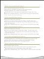
Smooth Movement
Position
Once the servo receives a movement command, it automatically creates a trapezoidal type speed
profile like the diagram below to control the position. With the servo operating according to the
acceleration/deceleration profile, it suppresses vibrations caused by the sudden acceleratiion and
deceleration as found in the square type speed profile and increases the energy efficiency while
leading to smoother movement. The servo chooses the trapezoidal type speed profile as a default
but profile could be changed according to usage to trapezoidal type, square type or triangle type.
Increasing
Accelated Period
Velocity
Time
Increasing
Accelated Period
Time
6
Durability
Manufactured using Super Engineering Plastic, our servos are highly durable, impact resistant
and designed to withstand even the high torque stress levels that go beyond the tolerance
specs of Engineering Plastic Gears.
Communication
Using Multi Drop TTL Full Duplex UART Serial communications protocol with maxium speed
of 0.667Mbps, single command can set the speed, position, LED, operational compliance,
stop and operational status of up to 254 servos simultaneoulsy at once.
54 Operating Parameters
Operational parameters such as speed, calibration, compliance to external force, LED could be
set by writing directly to the register, by using the Servo Manager downloaded from the web site
or by using the Servo Manager Kit sold separately.
Resolution
0.325 degrees resolution provides very accurate smooth control and minimal vibration.
Maximum Operating Angle
Position Control Mode : 0 ~ 320˚ possible but recommended range is within 0 ~ 300˚
Speed Control Mode : Continuous rotation possible with rotation speed control
Compliance Control
By controlling the torque according to the discrepancy between the goal position and the
actual position, Compliance Control provides certain measure of elasticity to absorb the shock
from the external force.
Data Feedback
Data feedback from the internal temperature, position, and overload sensors.
Protection Features
Internal temperature sensor monitors the motor and the circuit temperature and issues Overheating
Protection Error if the temperature moves beyond set value.
Overload Protection Error is issued when the load stress on the servo goes beyond the set value.
These safety features protec the sevo from the potential damage and prolongs the servo life.
7
Self Diagnosis
Servos are capable of diagnosing seven different types of errors which are then indicated by the
LED. Servo UI is used to set the function and timing of the Overload Protection.
( protects the servo when the overload occurs by releasing the torque )
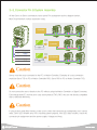
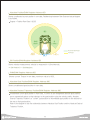
Multi Drop Network
Expandable Multi Drop type Network with 1:n configuration.
(single controller connected to multiple “n” number of servos).
ID : 0
ID : 1
ID : n
ID : 253
Controller
or
232 Gender
Communication
BUS
TXD
RXD
Multi Function LED
User has direct control the three independently controlled LEDs Red/Green/Blue which are used for
diagnostics and decorative purposes. LED commands are sent together with the Operation command.
※ In case of an error, diagnostics function ignores all LED commands and the Red LED starts to blink periodically
according to the setting.
Metal Ball Bearing (DRS-0201)
Ball bearing installed on the 4th gear shaft will prevent wear, sloping and provide protection from external
shocks that can bend the shaft or throw the gear out of mesh.
※ DRS-0101 : Plastic Bushing
※ DRS-0201 : Metal Ball Bearing
8
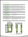
2-3. Specification
Dimension / Weight
Reduction Ratio
Gear Material
45mm(W) x 24.0mm(D) x 31mm(H) / 45g [1.59 oz]
45mm(W) x 24.0mm(D) x 31mm(H) / 60g [2.12 oz] (DRS-0201)
[1.77 in.(W) x 0.94 in.(D) x 1.22 in.(H)]
1 : 266
Super Engineering Plastic, Heavy Duty Metal (DRS-0201)
Input Voltage
Rated Current Motor
Stall Torque /
Maximum Speed
7~12VDC(Optimized 7.4V)
450mA @ 7.4V : 1.7kgf.cm, 670mA @ 7.4V : 2.2kgf.cm (DRS-0201)
Carbon Brush Cored DC, Metal Brush Coreless DC (DRS-0201)
12kgf.cm [166.8 ozf.in.] / 0.166s/60˚@7.4V
24kgf.cm [333.6 ozf.in.] / 0.147s/60˚@7.4V (DRS-0201)
Resolution
0.325˚
Operating Angle
Temperature
320˚, Continuous Rotation
0 ~ 85℃ [32℉~185℉]
Communication Link
ID, Maximum Baud Rate
Feedback
Full Duplex Asynchronous Serial(TTL Level),
Binary Packet, Multi Drop
0 ~ 253, 254(Broadcast only)
0.67Mbps
Position, Speed, Temperature, Load, Voltage etc.
PID, Feedforward, Trapezoidal Velocity Profile, Velocity Override,
Torque Saturator & Offset, Overload Protection,
Neutral Calibration, Dead Zone
54 Selectable Setting Parameters(※ Servo Manager Kit Required)
Control Algorithm
30.0°
24mm [0.94 in.]
Horn
33.6mm [1.32 in.]
29mm [1.14 in.]
Ø14mm [Ø0.55 in.]
9.7mm
[0.38 in.]
Ø19mm [Ø0.75 in.]
28.3mm [1.11 in.]
45mm [1.77 in.]
10.7mm
[0.42 in.]
3mm
[0.11 in.]
18mm [1.42 in.]
31mm [1.22 in.]
※ Refer to Pages 51 and 52 for connector specs.
9
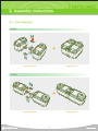
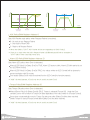
3. Assembly Instructions
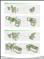
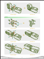
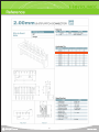
3-1. Joint Assembly
TYPE 1
12
12
12
12
8
8
8
8
12
12
8
12
12
12
Assembly Diagram
Assembled Unit
TYPE 2
12
12
12
12
8
8
8
8
12
12
12
12
Assembly Diagram
Assembled Unit
10
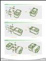
TYPE 3
12
PHM 2X4
(Option)
10
Bracket
(not included)
12
10
10
12
10
Bracket
(not included)
12
Assembly Diagram
Assembled Unit
TYPE 4
12
PHM 2X4 (Option)
12
10
Bracket
(not included)
10
10
10
12
Bracket
(not included)
12
Assembly Diagram
Assembled Unit
TYPE 5
12
12
12
9
12
12
9
9
12
12
9
12
Assembly Diagram
Assembled Unit
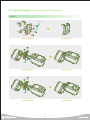
11
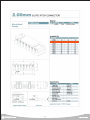
3-2. Joint Assembly (Optional Brcket and Bolt Required)
TYPE 1
10
PHM 2X4 (Option)
10
10
10
별매
Assembly Diagram
Assembled Unit
12
12
11 11
11
12
11
12
Assembly Diagram
Assembled Unit
12
12
11
11
11
12
11
12
Assembly Diagram
Assembled Unit
12
TYPE 2
10
10
10
12
10
12
12
12
Assembly Diagram
Assembled Unit
12
12
11
11
11
12
11
12
Assembly Diagram
Assembled Unit
TYPE 3
10
10
PHM 2X6 (Option)
10
9
10
PHM 2X4 (Option)
10
9
10
Assembly Diagram
12
12
Assembled Unit
12
12
12
12
12
12
Assembly Diagram
Assembled Unit
13
12
12
12
12
12
12
12
12
Assembly Diagram
Assembled Unit
TYPE 4
10
10
9
10
9
9
10
PHM 2X6 (Option)
9
Assembly Diagram
12
12
Assembled Unit
12
12
12
12
12
Assembly Diagram
Assembled Unit
12
12
12
12
12
12
Assembly Diagram
Assembled Unit
14
12
12
12
12
12
12
12
Assembly Diagram
Assembled Unit
TYPE 5
10
10
9
9
PHM 2X6 (Option)
10
9
9
Assembly Diagram
Assembled Unit
12
12
12
12
12
12
12
12
Assembly Diagram
Assembled Unit
15
TYPE 6
10
10
9
PHM 2X6
(Option)
9
10
9
9
Assembly Diagram
Assembled Unit
12
12
12
12
12
12
12
12
Assembly Diagram
Assembled Unit
TYPE 7
9
PHM 2X6
(Option)
9
9
9
Assembly Diagram
Assembled Unit
16
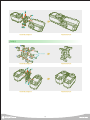
3-3. Connector Pin & System Assembly
All the Servo to Servo connectors have same Pin assingment as the diagram below.
Multi Drop Network makes expansion easy.
Controller
RS232
Cable
Controller
Pin #
Description
1
2
3
4
GND
VDD
TXD
RXD
RS232
Cable
232 Gender
Caution
Servos must be cross connected to the PC or Motion Controller. Examples of cross connection
would be Servo TXD to PC or Motion Controlller RXD, Servo RXD to PC or Motion Controller TXD.
Caution
Do not connect the servo directly to the PC without using the Motion Controller or Signal Converter.
Even though both PC and the servo uses serial protocol (TXD, RXD ) they are not directly compatible
due to electrical difference.
Caution
If using custom made Wire Harness, make sure to check that connector pin assingments are in correct
order. Servo LED will blink once if it is receiving power properly. If the LED does not blink, check the
connector pin assignment and the power supply Voltage and Amp.
17
4. Operation
4-1. Communications Protocol
Introduction
Servo Controller communicates with the servos in the network by sending a Request Packet and
receiving ACK Packet back from the servo. The example below shows the controller sending a
Request Packet to the Servo n and receiving ACK packet back from the Servo n. Regardless
of the number of servos in the network, only the servo with correct ID (n) will acknowledge the
Request Packet and send the ACK Packet to the controller.
TX : Request Packet
Controller
or
PC
ID : n
ID : 0
RX : ACK Packet
Data Bit : 8
Stop Bit : 1
Parity : None
Flow Control : None
Baud Rate : 57,600 / 115,200 / 0.2M / 0.25M / 0.4M / 0.5M / 0.667M
Communication
Protocol
※ The communications speed of the PC communication ports or USB to Serial Cable can be limited by the
hardware or by the device driver. If problem occurs, check the Baud Rate of the involved port of peripheral to
make sure it supports 115,200bps. If the supported Baud Rate can not found, set the Baud Rate to 115,200bps
or 57,600bps and try again. The default factory setting for DRS-0101 and DRS-0201 is 115,200bps.
Packet
Type
Header
Packet Size
pID
CMD
Check Sum1
Check Sum2
Data[n]
Value
0xFF 0xFF
7~223
0~0xFE
1~9
Refer to Detail
Refer to Detail
Refer to Detail
1
1
1
1
1
MAX 216
Byte
1
1
18
Header
Indicates start of the Packet.
Header
Type
Value
0xFF
0xFF
Byte
1
1
Packet Size
Refers to total Packe size ( in Bytes ) from Header to Data. The maximum Packet Size 233, if the
packet size is larger than 223 Bytes, packet may not be recognized. Minimum packet size is 7
which is packet without any data.
pID
Unique pID value can range from 0 ~ 253 which is total number of servos in the network.
Care must be taken when using pID value of “0xFE” which is a special value that affects all the
servos in the network.
※ To avoid confusion with Servo ID, ID within the packet is deonoted pID
Type
pID
Value
0 ~ 0xFE
Byte
1
CMD
CMD is actual instructions for the servo to perfom when packet is received. There are 9 types of
CMD in Request Packet EEP_WRITE(0x01), EEP_READ(0x02), RAM_WRITE(0x03), RAM_READ(0x04),
I_JOG(0x05), S_JOG(0x06), STAT(0x07), ROLLBACK(0x08), REBOOT(0x09). ACK Packet also has
equivalent set of CMD, but to distinquish from the Request CMD, ACK Packet adds 0x40.
For example, ACK Packet CMD for Request Packet EEP_WRITE(0x01)would be 0x41.
Type
CMD
Value
0x01 ~ 0x09 : Request Packet
0x41 ~ 0x49 : ACK Packet
Byte
1
19
Check Sum1
Check Sum1 is used to check for errors in the Packet. Check Sum1 is calculated as follows,
Check Sum1 = (PacketSize ^ pID ^ CMD ^ Data[0] ^ Data[1] ^ …… ^ Data[n]) & 0xFE.
Header, Check Sum1, Check Sum2 are not included in the calculation.
※ ‘A ^ B’ : Bit Exclusive OR Operator, A is different from B 1(True), same 0(False)
Type
Check Sum1
Value
(PacketSize ^ pID ^ CMD ^ Data[0] ^ Data[1] ^ …… ^ Data[n])&0xFE
Byte
1
Check Sum2
Checksum2 is also used to check for errors in the Packet. Check sum2 is calculated as follows,
Check Sum2 = ( ~CheckSum1) & 0xFE
※ ~ A’ : Bit Not Operator, A = 0 1(True), A = 1 0(False)
Type
Check Sum2
Value
(~CheckSum1) & 0xFE
Byte
1
Data[n]
Number of Data depends on CMD and some CMD may not have Data field.
Refer to CMD for details.
Type
Data
Value
Refer to CMD for details
Byte
Max216
20
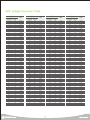
4-2. Register Map
Register Map are values residing within the Servo and contain data pertaining to current servo
status and operation. Registers are either Non-Volatile or Volatile.
Users are able to control the servos by using Request Packet and ACK Packet to either check or
change the data in the Register Map.
Non-Volatile Register Map
Non-Volatile memory retains data without power. Once the power is turned on, data in the Non-Volataile
memory in EEP Register are copied to the RAM Register which is Volatile memory. Data in the Non-Volatile
memory does not have direct affect on the operation of the servo once it has been copied to the RAM
Register. Rebooting the servo will again copy the data from EEP Register to the RAM Register.
Address
Address refers to the address of the Register. To Read/Write to the Register, Register address must be
included in the Packet.
Default
Factory Default Value, Rollback Protocol is used to return all values to Factory Default Value.
Valid Range
Range of valid data values servo can have. Input of data beyond the Valid Range will possibly result
in unpredictable servo behavior.
RO(Read Only), RW (Read Write)
RO refers to read only Registers. Writing to RO Register will result in error.
RO Registers hold fixed values such as Model #, Version or sensor values used for feedback.
RW refers to Registers which be both read and written to.
※ e (Reg_Name) : Refers to Reg_Name in EEP Register.
※ r (Reg_Name) : Refers to Reg_Name in RAM Register.
ADDRESS
Type
Bytes
Default
Valid Range
RW
0
Model No1
1
0x01
-
RO
1
Model No2
1
0x01
-
RO
2
Version1
1
0x00
-
RO
3
Version2
1
0x90
-
RO
21
Description
Shows DRS-0101 model #
(※ For DRS-0201, Model No1 is 0x02)
Firmware Version
ADDRESS
Type
Bytes
Default
Valid Range
RW
4
Baud Rate
1
0x10
Refer to Pg 26
RW
5
Reserved
1
0x00
-
-
6
ID
1
0xFD
0x00 ~ 0xFD
RW
Servo ID(0xFE : Can be used as
Broadcasing ID. ID not assignable)
7
ACK Policy
1
0x01
0x00 ~ 0x2
RW
Refer to Pg 33
8
Alarm LED Policy
1
0x7F
0x00 ~ 0x7F
RW
Activates alarm LED according to policy
9
Torque Policy
1
0x35
0x00 ~ 0x7F
RW
Releases torque according to policy
10
Reserved
1
-
-
-
11
Max. Temperature
1
0xDE
0x00 ~ 0xFE
RW
Maximum allowed temp(0xDF : 85℃)
12
Min. Voltage
1
0x5B
0x00 ~ 0xFE
RW
Minimum allowed voltage(0x5B : 6.714DCV)
13
Max. Voltage
1
0x89
0x00 ~ 0xFE
RW
Maximum allowed voltage(0x89 : 10DCV)
14
Acceleration Ratio
1
0x19
0x00 ~ 0x32(50)
RW
15
Max. Acceleration Time
1
0x2D
0x00 ~ 0xFE
RW
Ratio of time to reach goal position
to acceleration or decceleration
Max acceleration time, 11.2ms interval
Acceleration(0x2D : 504ms)
16
Dead Zone
1
0x00
0x00 ~ 0xFE
RW
Outside control/sensor range
17
Saturator Offset
1
0x00
0x00 ~ 0xFE
RW
Refer to Pg 36
18
Saturator Slope
2
0x0000
0x0000 ~ 0x7FFF
RW
Refer to Pg 36
20
PWM Offset
1
0x00
-128 ~ 127
RW
21
Min. PWM
1
0x00
0x00 ~ 0xFE
RW
22
2
0x03FF
0x0000 ~ 0x03FF
RW
2
0x03FE
0x0000 ~ 0x7FFE
RW
26
Max. PWM
Overload PWM
Threshold
Min. Position
PWM Offset value
Refer to Pg 37
Sets minimum PWM value
Refer to Pg 37
Sets maximum PWM value
Refer to Pg 37
Sets PWM overload treshold range
Refer to Pg 34
2
0x0015
0x0000 ~ 0x03FF
RW
Minimum position value(0~1023)
28
Max. Position
2
0x03EA
0x0000 ~ 0x03FF
RW
Maximum position value(0~1023)
30
Position Kp
2
0x01B8
0x0000 ~ 0x7FFF
RW
Proportional Gain,
32
Position Kd
2
0x1F40
0x0000 ~ 0x7FFF
RW
Derivative Gain,
34
Position Ki
2
0x0000
0x0000 ~ 0x7FFF
RW
Integral Gain,
2
0x0000
0x0000 ~ 0x7FFF
RW
Refer to Pg 35
2
0x0000
0x0000 ~ 0x7FFF
RW
Refer to Pg 35
40
Position Feed forward
1st Gain
Position Feedforward
2nd Gain
Reserved
2
-
-
-
Reserved
42
Reserved
2
-
-
-
Reserved
44
LED Blink Period
1
0x2D
0x00 ~ 0xFE
RW
45
ADC Fault Check Period
1
0x2D
0x00 ~ 0xFE
RW
46
Packet Garbage
Check Period
1
0x12
0x00 ~ 0xFE
RW
47
Stop Detection Period
1
0x1B
0x00 ~ 0xFE
RW
24
36
38
22
Description
Communication Speed
Reserved
Reserved
Alarm LED blink period accoring to policy,
11.2ms/Tick, 0x2D : 504ms
Temp/voltage error check period,
11.2ms/Tick, 0x2D : 504ms
Packet Error check period,
11.2ms/Tick, 0x12 : 201ms
Stop detection check period,
11.2ms/Tick, 0x1B : 302ms
ADDRESS
Type
Bytes
Default
Valid Range
RW
Description
48
Overload Detection Period
1
0x96
0x00 ~ 0xFE
RW
Overload Check Interval
11.2ms/Tick, 0x96 : 1.68s
49
Stop Threshold
1
0x03
0x00 ~ 0xFE
RW
Stop Threshold
50
Inposition Margin
1
0x03
0x00 ~ 0xFE
RW
Offset Threshold
51
Reserved
1
-
-
-
Reserved
52
Reserved
1
-
-
-
Reserved
53
Calibration Difference
1
0
-128 ~ 127
RW
Servo Compensation
※ 2 Byte Variable Byte Order : (Little Endian ) Most significant byte is stored int the higher address.
[ Example ] : e(Position Kp) Address is 30~31. To store 0x1234(4460), store the least significant first
Address(30)= 0x34, and most significant digit last Address(31)=0x12
※ Intel & Alpha Processesors use Little Endian, whereas most of the RISC Processers & Mortorola Processors
use Big Endian.
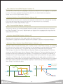
Max. PMW, Dead Zone
PWM is the value representing engergy input to the Servo. When the energy is increased, servo
torque or speed increases.
Max. PWM : Limits maximum PWM, In other words, limits the maximum energy supplied to the Servo.
Energy use is optimized by limiting the maximum torque or speed of the servo.
Dead Zone : Servo moves to reach the exact Goal Position. When the difference (Error) between the
current position and the goal position becomes 0, the force drops to 0 and the servo stops.
Dead Zone provides flexibility to the servo operation by increasing the range where the force drops to 0.
If the difference (Error) is less than the Dead Zone, servo assumes it has reached the goal position and stops.
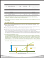
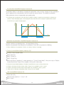
※ “What does operational flexibility” mean?
In the graph below, green line is the PWM level without the Max. PWM and Dead Zone set. The yellow line is
the PWM level with the Max.PWM and the Dead Zone set. The yellow line shows the PWM dropping to 0 within
the Dead Zone even though Goal Position has not been reached. Looking at the right side of the graph, even
though the green line is above (larger) than the Max.PWM, actual PWM value (yellow line) is within the Max.PWM.
PWM
※ Setting the Dead Zone too large will increase the discontinuous PWM section and lead to decreased
controllability. Recommended Dead Zone value is below 10.
Max. PMM
Max. PWM
Before Setting
Goal Position
After Setting
+Position
Dead Zone
Max. PWM, Dead Zone
23
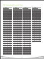
Volatile Register(RAM Register) MAP
Volatile Memory has direct affect on the operation of the Servo and reverts to default (EEP Register)
value when the Servo is reboot even though RAM register value has been changed to change the
servo operating parameters. Read/Write has to be performed to RAM Register value to operate
the Servo, change the operating parameters or to check servo status.
ADDRESS
Type
Bytes
Valid Range
RW
0
ID
1
0x00 ~ 0xFD
RW
Servo ID(0xFE : Can be used as
Broadcasting ID, ID not assignable)
1
ACK Policy
1
0x00 ~ 0x2
RW
Refer to Pg 33
2
Alarm LED Policy
1
0x00 ~ 0x7F
RW
Activates alarm LED according to Policy
3
Torque Policy
1
0x00 ~ 0x7F
RW
Releases Torque according to Plolicy
4
Reserved
1
-
-
5
Max. Temperature
1
0x00 ~ 0xFE
RW
Maximum allowed temp(0xDF : 85℃)
6
Min. Voltage
1
0x00 ~ 0xFE
RW
Minimum allowed voltage(0x5B : 6.714VDC)
7
Max. Voltage
1
0x00 ~ 0xFE
RW
Maximum allowed voltage(0x89 : 10VDC)
8
Acceleration Ratio
1
0x00 ~ 0x32(50)
RW
9
Max. Acceleration
1
0x00 ~ 0xFE
RW
Ratio of time to reach goal position
to acceleration or decceleration
Max acceleration time, 11.2ms interval
Acceleration(0x2D : 504ms)
10
Dead Zone
1
0x00 ~ 0xFE
RW
Outside control range
11
Saturator Offset
1
0x00 ~ 0xFE
RW
Refer to Pg 36
12
Saturator Slope
2
0x0000 ~ 0x7FFF
RW
Refer to Pg 36
14
PWM Offset
1
-128 ~ 127
RW
15
Min. PWM
1
0x00 ~ 0xFE
RW
16
Max. PWM
2
0x0000 ~ 0x03FF
RW
18
Overload PWM Threshold
2
0x0000 ~ 0x7FFE
RW
PWM Offset value
Refer to Pg 37
Set minimum PWM value
Refer to Pg 37
Set maximum PWM value
Refer to Pg 37
Set PWM Overload treshold range
Refer to Pg 34
20
Min. Position
2
0x0000 ~ 0x03FF
RW
Minimum position value(0~1023)
22
Max. Position
2
0x0000 ~ 0x03FF
RW
Maximum position value (0~1023)
24
Position Kp
2
0x0000 ~ 0x7FFF
RW
Proportional Gain
26
Position Kd
2
0x0000 ~ 0x7FFF
RW
Derivative Gain
28
Position Ki
2
0x0000 ~ 0x7FFF
RW
Integral Gain
30
2
0x0000 ~ 0x7FFF
RW
Refer to Pg 35
32
Position
Feedforward 1st Gain
Position
Feedforward 2nd Gain
2
0x0000 ~ 0x7FFF
RW
Refer to Pg 35
34
Reserved
2
-
-
Reserved
36
Reserved
2
-
-
Reserved
38
LED Blink Period
1
0x00 ~ 0xFE
RW
24
Description
Reserved
Alarm LED blink period according to Policy
11.2ms/Tick, 0x2D : 504ms
ADDRESS
Type
Bytes
Valid Range
RW
1
0x00 ~ 0xFE
RW
1
0x00 ~ 0xFE
RW
Description
40
ADC Fault
Detection Period
Packet Garbage
Detection Period
41
Stop Detection Period
1
0x0000 ~ 0x7FFF
RW
42
Overload Detection Period
1
0x00 ~ 0xFE
RW
Temp/Voltage error check interval
11.2ms/Tick, 0x2D : 504ms
Packet Error check interval,
11.2ms/Tick, 0x12 : 201ms
Stop detection check interval,
11.2ms/Tick, 0x1B : 302ms
Overload check interval,
11.2ms/Tick, 0x96 : 1.68s
43
Stop Threshold
1
0x00 ~ 0xFE
RW
Stop Threshold
44
Inposition Margin
1
0x00 ~ 0xFE
RW
Offset Threshold
45
Reserved
1
-
-
Reserved
46
Reserved
1
-
-
Reserved
47
Calibration Difference
1
-128 ~ 127
RW
Servo compersation
48
Status Error
1
0x00 ~ 0x7F
RW
Refer to Pg 39
49
Status Detail
1
0x00 ~ 0x7F
RW
Refer to Pg 39
50
Reserved
1
-
-
Reserved
51
Reserved
2
-
-
Reserved
52
Torque Control
1
MASK : 0x60
RW
Torque enable states (Refer to Pg 28)
53
LED Control
1
0x00 ~ 0x07
RW
0x01:Green, 0x02:Blue, 0x04:Red
54
Voltage
2
0x00 ~ 0xFE
RO
55
Temperature
2
0x00 ~ 0xFE
RO
56
Current Control Mode
2
0~1
RO
Input voltage Raw Data, 8Bit
(Refer to detail in Pg 31)
Current temp Raw Data, 8Bit
(Refer to detail in Pg 31)
0 : Position Control,
1 : Turn / Velocity Control
57
Tick
2
0x00 ~ 0xFF
RO
11.2ms/Tick
58
Calibrated Position
2
-
RO
Calbrated current position Raw Data 10Bit(0~1023)
60
Absolute Position
2
-
RO
Uncalibrated absolute position Raw Data
62
Differential Position
2
-
RO
Position change/11.2ms
64
PWM
2
-
RO
Torque Raw Data
66
Reserved
2
-
-
68
Absolute Goal Position
2
-
RO
Uncalibrated goal position Raw Data
70
Absolute Desired
Trajectory Position
2
-
RO
Current intermediate goal position in trajectory
72
Desired Velocity
1
-
RO
Desired speed based on speed profile Raw Data
39
25
Reserved
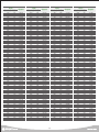
Register Detail
NO
Type
Bytes
EEP ADDR
RAM ADDR
1
Model No1
1
0
-
2
Model No2
1
1
-
3
Version1
1
2
-
4
Version2
1
3
-
RW
RO
Servo Model Name
RO
Firmware Version
5
Baud Rate
1
4
-
RW
6
Reserved
1
5
-
-
7
8
9
ID
ACK Policy
Alarm LED Policy
1
1
1
6
0
7
1
8
2
RW
RW
Sets Alarm LED policy when error. r(LED Policy)
& r(Status Error) TRUE > LED blink
LED blink period set by r(LED Blink Period)
When error LED blink > Ignore r(LED Control) value
Resolve r(Status Error) Error to make
r(LED Control) function normally
r(Servo Policy) & r(Status Error) TRUE >
Torque release(Torque Off)
When Torque released, by errorTorque
On not possible regardless of value in
r(Torque Control)
Servo does not automaticallly revert to Torque
On even after r(Status Error) has been resolved
Enable Toque On using r(Torque Control)
after r(Status Error) has been resolved
9
3
RW
11
Reserved
1
10
4
-
12
Max. Temperature
13
14
Min. Voltage
Max. Voltage
1
1
12
6
13
7
26
Reserved
Sets ACK packet reply policy when
Request packet received
0 : No reply
1 : Only reply to Read CMD
2 : Reply to all Request Packet
※ When CMD is STAT, ACK packe will
be sent regardless of r(ACK Policy)
※ When pID(Boradcast pID)is 254 no reply
(Exception when CMD is STAT)
1
5
Default Baud Rate is 115,200bps
0x02 : 666,666bps
0x03 : 500,000bps
0x04 : 400,000bps
0x07 : 250,000bps
0x09 : 200,000bps
0x10 : 115,200bps
0x22 : 57,600bps
※ Baud Rate error within 3%
RW
Torque Policy
11
(※ for DRS-0201, Model No1 is 0x02)
Servo ID, Error when same ID exists
within the same network.
Range 0 ~ 253
※ pID up to 254
Servo ID maximum 253
10
1
Description
Reserved
RW
Maximum operational temperature
When r(Temperature) is greater than
r(Max. Temperature) r(Status Error) "Exceed
Temperature Limit" activated
RW
Minimum operational voltage
When Servo input voltage r(Voltage) is below
r(Min. Voltage), r(Status Error) "Exceed
Voltage Limit" activated
Voltage = 0.074 X ADC
RW
Maximum operational voltage
When Servo input voltage r(Voltage) is greather
than r(Max. Voltage), r(Status Error) "Exceed
Voltage Limit" activated
Voltage = 0.074 X ADC
NO
15
구분
Acceleration Ratio
Bytes
1
EEP ADDR
RAM ADDR
14
8
RW
RW
Description
Acceleration ratio regarding velocity Profile
Ratio of operation time of Motion command
(I_JOG, S_JOG), %
Acceleration ratio is same as decceleration ratio
Maximum r(Acceleration Ratio) value is 50
Ex) When operating time is 100ms and
r(Acceleration Ratio) is 20 : Acceleration
time is 100 X 0.2 = 20ms
※ When r(Acceleration Ratio)is 0, speed
profile is rectangle
※ When r(Acceleration Ratio) is below 50,
velocity profile is triangle
16
Max. Acceleration Time
1
15
9
RW
Maximum acceleration time(1 : 11.2ms)
When maximum acceleration time r(Max.
Acceleration Time) is 254 = 2.844sec
※ When r(Max. Acceleration Time) is 0 velocity
profile is rectangle
17
Dead Zone
1
16
10
RW
Outside control range
Dead Zone only funtions within position control
18
Saturatior Offset
1
17
11
RW
Select Offset at Saturator curve
※ Not applicapable in nfinite Turn
(continuous turn)
RW
Saturator does not work when
r(Staturation Slop)=0
Actual Saturator Slop = r(Saturator Slop) / 256
※ Not applicapable infinite Turn Mode
(continuous turn)
RW
PWM Offset value
PWM increases by r(PWM Offset) amount
※ When PWM is at maximum value, Servo at
current load outputs maximum Torque and speed
※ When PWM is 0, Servo stopped
※ Maximum PWM value 1023
※ Not applicapable innfinite Turn(continuous turn)
RW
Minimum PWM = Sets Minimum Torque
※ When PWM is at maximum value, Servo at
current load outputs maximum Torque and
speed
※ When PWM is 0, Servo stopped
※ Maximum PWM value 1023
RW
Maximum PWM = Sets Maximum Torque
※ Smaller this value, Maximum Servo Torque decreases
※ When PWM is at maximum value, Servo at
current load outputs maximum Torque and
speed
※ When PWM is 0, Servo stopped
※ Maximum PWM value 1023
RW
Sets overload activation point
External force divided into 0~1023 steps,
Overload error when force > r(Overload PWM
Threshold) is exerted for period longer than
r(Overload Detection Period)
Not activated when This value is > 1023
RW
Minimum operational angle
When requested position angle is less than
r(Min. Position), “Exceed Allowed POT Limit”
activated. Actual operation is limited to
r(Min. Position)
RW
Maximum operational angle
When requested position angle is greater than
r(Max. Position), "Exceed Allowed POT Limit"
activated. Actual operation is limited to
r(Max. Position)
19
20
21
22
23
24
25
Saturator Slope
PWM Offset
Min. PWM
Max. PWM
Overload PWM
Threshold
Min. Position
Max. Position
2
1
1
2
2
2
2
18
12
20
14
21
15
22
16
24
18
26
20
28
22
27
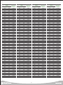
NO
Type
Bytes
EEP ADDR
RAM ADDR
RW
26
Position Kp
2
30
24
RW
Proportional Gain
27
Position Kd
2
32
26
RW
Derivative Gain
28
Position Ki
2
34
28
RW
Integral Gain
29
Position Feedforward 1st Gain
2
36
30
RW
Refer to Pg 35
30
Position Feedforward 2nd Gain
2
38
32
RW
Refer to Pg 35
31
Reserved
2
40
34
-
Reserved
32
Reserved
2
42
36
-
Reserved
33
LED Blink Period
1
44
38
RW
Alarm LED blink period according to
policy 11.2ms
34
ADC Fault Check Period
1
45
39
RW
Temp/Voltage error check interval
1 = 11.2ms
Error activated if Temp/V error lasts longer
than the check interval
35
Packet Garbage
Check Period
RW
Incomplete packet error check interval
1 = 11.2ms
Incomplete packet is deleted if it reamains longer
than the error check interval
1
46
40
Description
36
Stop Detection
Period
1
47
41
RW
Time limit to determine if the servo has
stopped
1 = 11.2ms
Servo confirmed Stopped if stoppage lasts
past set time limit
37
Overload Detection Period
1
48
42
RW
Overload error check interval
38
Stop Threshold
1
49
43
RW
When position change is less than r(Stop Threshold),
Servo seen as having stopped
39
Inposition Margin
1
50
44
RW
Standard value to determine if goal position reached.
If deviation from goal position is less than
r(Inposition Margin) recognized as goal
position reached
40
Reserved
1
51
45
-
Reserved
41
Reserved
2
52
46
-
Reserved
42
Calibration Difference
1
53
47
RW
43
Status Error
1
-
48
RW
44
Status Detail
1
-
49
RW
45
Reserved
1
-
50
-
Reserved
46
Reserved
1
-
51
-
Reserved
47
Torque Control
1
-
52
28
RW
Used to calibrate Newtral point(POS. : 512)
Absolute position = Calibrated position +
r(Calibration Difference)
r(Calibration Difference) = Absolute position Newtral point(512)
Shows 7 different status
Refer to Pg 39
Shows 7 different status
Refer to Pg 39
Torque enable states
0x40 : Break On, 0x60 : Torque On
0x00 : Torque Free
When Torque enabled, Mode depends on
r(Current Control Mode) before Torque On.
※ r(Current Control Mode) defaults to
Position Control(0) when servo powered on
※ Torque On : Operation possible state
※ Break On : Opeation command (I_JOG,
S_JOG) not possible
※ Torque Free : Similar to Break On, Joints
manually movable.
NO
Type
Bytes
EEP ADDR
RAM ADDR
RW
Description
48
LED Control
1
-
53
RW
Servo LED control
When corresponding Bit value 1 = On, 0 = Off
(0x01 : Green, 0x02 : Blue, 0x04 : Red)
※ When alarm LED activated by r(Status Error)
and r(Alarm LED Policy). r(Led Control)
Write value ignored
49
Voltage
1
-
54
RO
Input Voltage = 0.074 X ADC
50
Temperature
1
-
55
RO
Internal Servo Temperature
51
Current Control
Mode
1
-
56
RO
Current time Servo control mode
I_JOG / S_JOG CMD Packet used to
change control mode
When Torque On using r(Torque Control),
Servo refers to r(Current Control Mode)
0 : Position Control
1 : Turn/Velocity Control(Continuous rotation)
52
Tick
1
-
57
RO
Servo operating time, Max setting 2.8672sec
0~255, 1 = 11.2ms
53
Calibrated
Position
2
-
56
RO
Calibrated position Raw Data
Refer to r(Calibration Difference)
54
Absolute Position
2
-
58
RO
Absolute position Raw Data
Angle = r(Absolute Position) X 0.325
55
Differential Position
2
-
60
RO
Shows speed measurement, interval 11.2ms
r(Diff Position)1 = 29.09deg/sec
56
PWM
2
-
62
RO
Current Torque, 1023 = Max Torque
57
Reserved
2
-
64
-
58
Absolute Goal
Position
2
-
66
RO
Absolute Goal position Raw Data
User selected Goal Position
Uncalibrated value
59
Absolute Desired
Trajectory Position
RO
Current Intermediate goal position based
on velocity Profile, Raw Data
r(Absolute Desired Trajectory Position) is
current goal position
RO
Current intermediate goal speed based
on velocity Profile, Raw Data
r(Desired Velocity) velocity required at
current time.
60
Desired Velocity
2
2
-
68
-
70
29
Reserved
Acceleration Ratio(RAM Register Address 8)
Acceleration Ratio is controlled by changing the parameter value and any change in the acceleration
ratio is applied to the decceleration ratio by exactly the same amount. The default Acceleration
Ratio parameter shows a trapezoidal type speed profile.
Velocity
※ Increasing the acceleration ratio will lead to sudden change in speed accompanied by vibration as
shows in blue rectangle graph. Decreasing the ratio will show slow increase in speed with smooth
movement as in green triangle graph.
시간
Play Time
Acceleration Time
Deceleration
Maximum Acceleration Time(RAM Register Address 9)
Controls maximum acceleration time, 1 is equaivalent to11.2ms.
Maximum acceleration time r(Maximum Acceleration Time) 254 is equivalent to 2.844sec.
※ When r(Maximum Acceleration Time) is 0, velocity Profile is rectangle.
Torque Control(RAM Register Address 52)
Controls Torque eanable states
0x40 : Break On
0x60 : Torque On
0x00 : Torque Free
When the torque is enabled, it’s mode depends on "Current Control Mode". If the servo was on Position
Control Mode when Torque ON is enabled, it will remain in that mode.
※ r(Current Control Mode) defaults to Position Control(0) when servo is first powered on
※ Control commands will only function when Torque On is enabled (I_JOG, S_JOG)
※ Control commands will not function when Break On is enabled (I_JOG, S_JOG)
※ Joints can be manually manipulated when Torque Free is enabled
LED Control(RAM Address 53)
Controls the LEDs.
When Bit value below is 1 = On, 0 = Off
0x01 : Green
30
0x02 : Blue
0x04 : Red
※ Whe Alarm LED is activated by the r(Status Error)or r(Alarm LED Policy), value in r(LED Control)
is ignored.
Voltage(RAM Register Address 54)
Shows the ADC(Analog Digital Conversion) value of the input voltage in raw data. The conversion
formula to actual voltage is shown below. Refer to the voltage ADC conversion table in page 49.
Voltage = 0.074 X ADC
Temperature(RAM Register Address 55)
Shows the ADC(Analog Digital Conversion) value of the current temperature in raw data.
Refer to temperature ADC conversion table in page 51.
Current Control Mode(RAM Register Address 56)
Shows the current control mode of the servo, I_JOG / S_JOG CMD Packet is used to change the mode.
When r(Torque Control) is used to change the servo state to Torque On, servo first refers to
r(Current Control Mode). For example, dafault mode of the servo when it is first powered up is
“Position Control Mode” and when the servo state is changed to Torque On, mode remains at
“Position Control Mode”. Servo has to be at Off state to change the control mode to “Turn/Velocity
Control Mode”. With Torque Off, use I_JOG / S_JOG CMD to switch to “Turn/Velocity Control Mode”.
After the switch, use r(Torque Control ) to to turn Torque On and the mode will have switched to
“Turn/Velocity Control Mode”.
0 : Position Control
1 : Turn / Velocity Control
※ Turn / Velocity Control : Infinite Turn(Continuous Rotation) Mode.
Tick(RAM Register Address 57)
Shows actual length of the servo tick time. Tick time can be changed from 0 ~ 255, tick time reverts
back to 0 after 255. 1 is equivalent to 11.2ms, 255 is equivalent to 2.856sec.
Calibrated Position(RAM Register Address 58)
Shows Calibrated Position in raw data. The relationship between Calibrated Position and Absolute
Position is as follows.
Calibrated Position = Absolute Position - r(Calibration Difference, 47 Address)
Degree = Position Raw Data X 0.325
31
Absolute Position(RAM Register Address 60)
Shows uncalibrated current position in raw data. Relationshop between Raw Data and actual degree
is as follows.
Degree = Position Raw Data X 0.325
512
1002
21
(159.8˚)
(-159.8˚)
Recommended Range
1023
(166.7˚)
0
26.7˚
Full Range
(-166.7˚)
Diff Position(RAM Register Address 60)
Shows velocity measurement, velocity is measured in 11.2ms intervals.
※ r(Diff Position) 1 = 29.09deg/sec
PWM(RAM Register Address 62)
Shows current Torque in raw data, maximum value is 1023.
Absolute Goal Position(RAM Register Address 66)
Shows uncalibrated goal position in raw data.
Absolute Desired Trajectory Position(RAM Register Address 68)
Uncalibrated current goal position in Raw Data. To arrive at user designated absolute goal position,
servo automatically plans out the trajectory to the goal position using the velocity profile. Absolute
Desired Trajectory Position is a “current” goal position or intermediate goal position to be reached on
the way to final goal position.
Refer to the diagram to see the relationship between Absolute Goal Position and the Absolute Desired
Trajectory Position.
32
Velocity
Position
Absolute Goal
Position
Play Time
Absolute Desired
Trajectory Position
Desired Velocity
Time
Command
recevied
Time
Command
recevied
Current
Current
ACK Policy(RAM Register Address 1)
Sets ACK Packet reply policy when Request Packet is received.
0 : No reply to any Request Packet
1 : Only reply to Read CMD
2 : Reply to all Request Packet
※ When the CMD is “STAT” ACK Packet will be sent regardless of r(ACK Policy).
※ There is no reply when the pID in Request Packet is 254(Broadcast pID) with an exception of
“STAT” CMD in which case reply will be sent.
Alarm LED Policy(RAM Register Address 2)
Sets Alarm LED policy when Error is detected.
When (r(LED Policy) & r(Status Error)) is TRUE, Alarm LED starts to blink, Alarm LED blink period is set
by r(LED Blink Period).
When (r(LED Policy) & r(Status Error))is TRUE, Any values written to r(LED Control) will be ignored to
prevent confusion with Error state.
Error status r(Status Error) must be resloved first for r(LED Control) to function properly.
※ ’A&B’ : Bit And Operator, 1(True) only whe A and B are both (True)
Torque Policy(RAM Register Address 3)
Sets Torque Off policy when Error is detected.
When (r(Servo Policy) & r(Status Error))is TRUE, Torque is released (Torque Off). Under the Error
condition, servo will not return to Torque ON state regardless of the value written to r(Torque Control).
Servo does not automatically revert to Torque On state even after r(Status Error)has been resolved.
Enable Torque On using r(Torque Control) after r(Status Error) has been resloved.
※ ’A&B’ : Bit And Operator, 1(True) only whe A and B are both (True)
33
Maximum Temperature(RAM Register Address 5)
Maximum operational temperature shown in Raw Data.
When internal servo temperature r(Temperature) exceeds r(Max Temperature),
"Exceeded Temperature Limit" in r(Status Error) becomes active.
Resulting Alarm LED and Torque status can be changed using r(LED Policy), r(Servo Policy).
Default value is 0xDF(approximatley 85℃). Refer to conversion chart (Pg 51) for actual temerature.
※ ’A&B’ : 1(True) only whe A and B are both (True)
Minimum Voltage(RAM Register Address 6)
Mininmum input voltage shown in Raw Data.
When servo input voltage r(Voltage) is below r(Min Voltage), "Exceeded Voltage Limit" in
r(Status Error) becomes active. Resulting Alarm LED and Torque status can be changed using
r(LED Policy), r(Servo Policy).
Default value is 0x5B(approximately 6.74V). Refer to conversion chart (Pg 49) for actual voltage.
Maximum Voltage(RAM Register의 Address 7)
Maximum input voltage shown in Raw Data.
When servo input voltage r(Voltage) is exceeds r(Max Voltage), "Exceeded Voltage Limit" in
r(Status Error) becomes active. Resulting Alarm LED and Torque status can be changed using
r(LED Policy), r(Servo Policy).
Default value is 0x89(approximately 10.14V). Refer to conversion chart (Pg 49) for actual voltage.
Overload PWM Threshold(RAM Register Address 18)
Sets overload activation point. The overload point from external force can set from 0~1023.
Overload activates when external force is greater them r(Overload PWM Threshold).
Overload does not activate when the given value is greater than 1023
Minimum Position(RAM Register Address 20)
Minimum operational angle in Raw Data.
When requested position angle is less than r(Min Position), "Exceed Allowed POT Limit" in
r(Min Position) becomes active and the operation is limited to r(Min Position).
Default value is 0x15(approximately -159.8˚). Refer to conversi on charge in (Pg 53) for actual angle.
34
Maximum Position(RAM Register Address 22)
Maximum operational angle in Raw Data.
When requested position angle is greater than r(Max Position), "Exceed Allowed POT Limit" in
r(Max Position) becomes active and the operation is limited to r(Max Position).
Default value is 0x3EA(approximately 159.8˚). Refer to conversion chart in (Pg 53) for actual angle.
Position Kp(RAM Register Address 24)
Shows the Proportional Gain. Increasing the Position Kp increases, the response time but over
response (vibration, overshoot) will result if the increase is too large.
Position Kd(RAM Register Address 26)
Shows the Derivative Gain. Increasing the Position Kd will suppress the over response (vibration,
overshoot) from Position Kp but unstability may result if the increase is too large.
Position Ki(RAM Register Address 28)
Shows the Intergral Gain. Applied to correct small offset in Steady State. May result in response
lag if the increase is too large.
Position Feedforward Kd(RAM Register Address 30)
Shows Position Feedforward 1st Gain. Applied to increase Servo response time.
Position Feedforward Kdd(RAM Register Address 32)
Shows Position Feedforward 2nd Gain. applied to increase Servo response time.
LED Blink Period(RAM Register Address 38)
Shows the Alarm LED blink period set by the LED Policy when error occurs. 1 is equivalent to 11.2ms.
Default value is 0x2D(Approximately 504ms).
ADC Fault Check Period(RAM Register Address 39)
Temperature / Input voltage error check interval, 1 is equivalent to 11.2ms. Error activated if the
Temerature / Input voltage error lasts longer than the check interval.
Default value is 0x2D(Approximately 504ms).
Packet Garbage Check Period(RAM Register Address 40)
Incomplete Packet error check interval, 1 is equivalent to 11.2ms. Incomplete Packet is deleted if it
remains longer than the check interval. Default value is 0x12(Approximately 201ms)
35
Stop Detection Period(RAM Register Address 41)
Set time limit by which the servo stoppage is measured to determine if it has stopped. 1 is equivalent
to 11.ms. If the servo stoppage lasts beyond the time limit, it is determined to be stopped.
Default value is 0x1B ( Approximately 302ms )
Overload Detection Period(RAM Register Address 42)
Set time limit by which the servo overload is measured to determine if the overload has occured.
If the overload period lasts beyond the time limit, it is determined to be overloaded.
Default value is 0x96 ( Approximately 1.68s )
Stop Threshold(RAM Register Address 43)
The servo is seen as not moving (stopped) when the position movement of the servo is less than
the r(Stop Threshold). The servo is determined to be stopped if the stoppage lasts longer than the
r(Stop Detection Period).
Inposition Margin(RAM Register Address 44)
Standard value to determine if the goal position has been reached.
Goal position is judged to have been reached if the deviation is less than r(Inposition Margin).
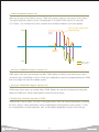
Saturator Offset, Saturator Slope(RAM Register Address 11, 12)
Saturation Offset and Saturation Slope work in similar manner to the PWM. However, by controlling
the limit per given section, accurate Saturator can be designed to provide flexible and elastic
response to the external force. The garph below shows the PWM with several settings.
The thick grey line show the PWM without the Saturator Offset and Slope settings. The red line
shows the actual PWM output with the Saturator Offset & Slope set. The blue dotted line shows the
boundary of the force restrained by the Saturator. The restrain by the Saturator on PWM value
increases when near the goal position and decreases when further away from the goal position.
The effect on PWM is smiliar to having a spring installed near the goal position, resulting in low
strength near the goal position and strength increasing with distance. Assuming the servo is stopped
at the goal position, Saturator allows flexible response to external force, and provides assistance
when trying to hold delicate object.
Before Saturator
Saturator
Slop
Goal
Position
-Position
-PWM
PWM Max
Dead Zone
Saturation Offset
+PWM
PWM Max
+PWM
-Position
+Position
Saturator
Slop
-PWM
36
Goal Position
After Saturator
+Position
PWM Offset(RAM Address 14)
When the 0 point of the PWM is moved, PWM will increase output by the amount of the Offset.
This output could be used to act as a compensator in a system where load is on one side
( Ex: Gravity ). By moving the 0 point, constant force directed towards 0 pont can applied.
+PWM
Force purshing upwards when
position reached.
PWM
Offset
-Position
+Position
Goal
Position
-PWM
Before setting
After setting
Minimum PWM(RAM Register Address 15)
PWM output value does not fall below the r(Min. PWM). Minimum PWM is used when there is jerky
movement due to tight fitting or friction in the servo application system but assigning Minimum PWM
that is too large may lead to unstable system.
Maximum PWM(RAM Register Address 16)
PWM output value does not exceed r(Max. PWM). Battery life could be increased by limiting the
Maximum PWM but it will also decrease the maximum servo torque.
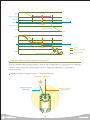
Relationship between Saturator & PWM
PWM results in servo output. As seen in the graph below, there are several parameters controlling
the servo output. These parameters can be manipulated to build optimum servo system. To see
the characteristics of each parameter, refer to the detailed explanation section in the manual.
37
+PWM
Dead Zone
r(Saturator Offset)
r(PWM MIN)
+Position
r(PWM MIN)
Goal Position
r(Saturator Offset)
r(Saturator Slop)/256
-PWM
+PWM
+Position
PWM limited by Dead Zone
Goal Position
Saturator
Saturator output PWM
-PWM
Final output PWM
PWM limited by Saturator
Calibration Difference(RAM Register Address 47)
Used to calibrate newtral point(standard). Used to make adjustments to compensate for assembly
variations when servos are used to build a system. Calibrated Difference is calculated by
following formula
Calibrated Position= Absolute Position - Calibration Difference
Calibration Difference
Calibrated Position
(ADC=512)
Absolute Position
(ADC=512)
38
Status Error, Status Details(RAM Register Address 48, 49)
Status
REG (Status Error)
Bits
7
6
Bits Value
5
4
3
2
REG (Status Error)
1
0
Bits
Comment
7
6
Bits Value
5
4
3
2
1
0
Comment
0
0X01
Exceed Input Voltage limit
0
0X01
Moving flag
1
0X02
Exceed allowed POT limit
1
0X02
Inposition flag
2
0X04
Exceed Temperature limit
2
0X04
Checksum Error
3
0X08
Invalid Packet
3
0X08
Unknown Command
4
0X10
Overload detected
4
0X10
Exceed REG range
5
0X20
Driver fault detected
5
0X20
Garbage detected
6
0X40
EEP REG distorted
6
0X40
MOTOR_ON flag
7
0X80
reserved
7
0X80
reserved
※ LED Policy, Servo Policy : Same as above
※ LED Policy : When Check bit error occurs,
LED(RED) blinks consistently
※ Servo Policy : When Check bit error occurs,
Torque is released to Freerun state
※ When Invalid Packet occurs, detailed
information is record in Status Detail Register
※ Moving/Inposition/MOTOR_ON flag are
Read only.
※ MOTOR_ON : Torque ON
Yellow lines above points to error detail when Status Error shows Invalid Packet(0x08).
Invalid Packet can be divided into 5 different causes, 4 shows in the Status Detail and other.
Portions of Status Detail are Read only but can be Written to by the Protocol.
Read only values are just ignored not actually Written to.
39
5. Command Set
To control the Servo, CMD is sent to the servo from the Controller in Binary
format. Our servos are controlled by 9 different CMDs. Once the Servo receives
Request Packet with included CMD, Servo performs requested operation and returns
the result to the Controller by ACK Packet.
5-1. [To Servo Module] - Request Packet
Type
CMD
Explanation
EEP_WRITE
0x01
Write Length number of values to EEP Register Address
EEP_READ
0x02
Request Length number of values from EEP Register Address
May not reply, depending on r(ACK Policy)
RAM_WRITE
0x03
Write Length number of values to RAM Register Address
RAM_READ
0x04
Request Lenght number of values from RAM Register Address
May not reply, depending on r(ACK Policy)
I_JOG
0x05
Able to send JOG command to maximum 43 servos.
I_JOG can set the operation timing of individual Servo
I_JOG Refer to Pg 48 for details
S_JOG
0x06
Able to send JOG command to maximum 53 servos.
S_JOG All the Servos operate simultaneously at same time
S_JOG Refer to Pg 48 for details
STAT
0x07
Status Error, Status Detail request
Always send reply reagardless of r(ACK Policy)
ROLLBACK
0x08
Change all EEP Regsters to Factory Default value
Apply changes after power reset
ID, and Baud Rate maybe exempt from Factory Default
depending on ID Skip and Baud Skip setting.
REBOOT
0x09
Request Reboot
5-2. [To Controller(ACK)] - ACK Packet
Type
CMD
Meaning
EEP_WRITE
0x41
CMD(0x01) Reply Packet
Default is no reply, Reply possible by changing r(ACK Policy) setting
EEP_READ
0x42
Repy with “n” number of values from EEP Register Address
May not reply depending on r(ACK Policy) setting
40
Type
CMD
Explanation
RAM_WRITE
0x43
CMD(0x03) Reply Packet
Default is no reply, reply possible by changing r(ACK Policy) setting
RAM_READ
0x44
CMD(0x04) Reply Packet
May not reply depending on r(ACK Policy) setting.
I_JOG
0x45
CMD(0x05) Reply Packet
Default is no reply, reply possible by changing r(ACK Policy) setting
S_JOG
0x46
CMD(0x06) Reply Packet
Default is no reply, reply possible by changing r(ACK Policy) setting
STAT
0x47
r(Status Error, Status Detail) Reply, Always Reply regadless of r(Ack Policy)
ROLLBACK
0x48
CMD(0x08) Reply Packet
Default is no reply, reply possible by changing r(ACK Policy) setting
REBOOT
0x49
CMD(0x09) Reply Packet
Default is no reply, reply possible by changing r(ACK Policy) setting
※ ACK option changeable by using r(ACK Policy)
※ ACK Packet CMD is Request Packet CMD + 0x40
※ Last 2 Bytes of the ACK Packet includes r(Status Error, Status Detail)
5-3. CMD(Command) Detailed Explanation
CMD
Explanation
EEP_READ
Request to read Length # of values from EEG Register Address
Optional Data length is 2
RAM_READ
Request to read Length # of values from RAM Register Address
Optional Data length is 2
EEP_WRITE
Request to write Length # of values to EEG Register Address
Optional Data length is Address & Length 1 Byte each + Length Byte
RAM_WRITE
Request to write Length # of values to RAM Register Address
Optional Data length is Address & Length 1 Byte each + Length Byte
I_JOG
Send instructions to multiple servos simultaneously, able to set position/time to each servo
independenltly. Able to set goal position time arrival time to each independently
I_Jog requires 5Bytes of data for each servo. Optional Data length of 50Bytes required
if sending instructions to 10 servos simultaneously
S_JOG
Able to send instructions to multiple servos simultaneousy, All serovs have same
operational timing. All servos arrive at goal position at same time.
S_Jog rquires 1byte for Playtime and 4Bytes for each servo. Optional Data length of
41Bytes required if sending instructions to 10 servos simultaneously
STAT
ROLLBACK
REBOOT
Request Servo Status r(Status Error, Status Detail)
STAT Packet always receive reply
Change all values in EEP_Register to Factory default value.
ID and Baud Rate maybe exempted from Factory Default by using ID Skip, Baud Skip Byte
Reboot Servo
41
6. Command Examples
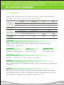
5-1. EEP_READ
Request 4 Bytes of information from EEP Register 0x1E Address of Servo ID(253). 4 Bytes from
EEP Register 0x1E Address are e(Position Kp)and e(Position Kd).
Header
EEP_READ
Example1
Packet Size
pID
CMD
0
1
2
3
4
0xFF
0xFF
9
Servo ID
0x02
0xFF
0xFF
0x09(9)
0xFD
0x02
Check Sum1
Check Sum2
5
6
EEP_READ
(Refer to Checksum formula)
Example1
0XEC
0X12
Data
7
8
Data[0]
Data[1]
0x1E
0x04
(Address)
(Length)
EEP READ
Request to read Length # of values from EEP Register Address. Data length is 2Bytes
( Address 1Byte + Length 1Byte )
Packet Size
7(Standad Size)+2(Data length)
pID
EEP READ CMD
Servo ID 0xFD(253)
0x02 (Refer to Pg 40)
CHECKSUM1 Formula
Checksum1 = (PacketSize ^ pID ^ CMD ^ Data[0] ^ Data[1]) & 0xFE
DATA[0]
Refers to starting address of EEP Register being Read, 0x1E(30) in the example is starting address
of Position Kp.
DATA[1]
Data[1], Refers to number of Bytes to be READ from the starting address, 0x04 in the example
means 4Bytes will be read. In other words, 4Bytes from Position Kp starting address will be read,
Position Kp(2Bytes variable)and Position Kd(2Bytes variable) will be read.
42
ACK Packet
Header
EEP_READ
ACK of Example1
Packet Size
pID
CMD
Check Sum1
Check Sum2
6
0xB2
0
1
2
3
4
5
0xFF
0xFF
0x0F
0xFD
0x42
0x4C
Data
7
8
Data[0]
Data[1]
0x1E
(Address)
9
10
11
12
13
14
(Length)
Data[2]
Data[3]
Data[4]
Data[5]
(Status Error)
(Status Detail)
0x04
0xB8
0x01
0x40
0x1F
0x00
0x00
Data[4]
Data[5]
CMD : Request Packet CMD(0x02) + 0x40, Reply with 0x42
e(Position Kp) : 440(0x1B8)
Position Kd : 8000(0x1F40)
Last 2Bytes of all ACK Packet contain Status Error(1Byte) and Status Detail (1Byte)
6-2. EEP_WRITE
ID(253), e(Position Kp) / Kd(Address 0x1E=30, 4Bytes Register) Kp = 200(0x00C8),
Kd = 1000(0x03E8) Write
Header
EEP_WRITE
Example1
Packet Size
pID
CMD
Check Sum1
Check Sum2
5
6
0
1
2
3
4
0xFF
0xFF
7+(2+Length)
Servo ID
0x01
0xFF
0xFF
0x0D(13)
0xFD
0x01
(Refer to Checksum Formula)
0XC8
0X36
Data
7
8
Data[0]
Data[1]
0x1E
(Address)
9
11
12
13
(Length)
Data[2]
Data[3]
Data[4]
Data[5]
0x04
0XC8
0X00
0XE8
0X03
Data[2] ~ Data[5]
Data[2], Data[3] will be changed to e(Position Kp) and Data[4], Data[5] will be changed to
e(Position Kp). You must input Byte in reverse order by Little Endian rule.
※ Refer to Pages 23 for Little Endian.
EEP Register
To apply changed EEP Register value, Servo has to be reboot first.
43
6-3. RAM_WRITE
Example 1
ID(253), r(LED Control), Address(0x35(53)) Request Green LED On.
Example 2
ID(253), r(Status Error, Status Detail), Request to Clear Address(0x30(48)) to "0".
Example 3
ID(253), r(Torque Control), Request to write 0x60 to Address(0x34(52)) for Torque On.
※ Make sure to haveTorque On before (I_JOG, S_JOG) command to avoid error.
Header
RAM_WRITE
Packet Size
pID
CMD
Check Sum1
Check Sum2
5
6
0
1
2
3
4
0xFF
0xFF
7+(2+Length)
Servo ID
0x03
Example1
0xFF
0xFF
0x0A(10)
0xFD
0x03
0xC0
0x3E
Example2
0xFF
0xFF
0x0B(11)
0xFD
0x03
0xC6
0x38
Example3
0xFF
0xFF
0x0A(10)
0xFD
0x03
0xA0
0x5E
(Refer to Checksum Formula)
Optional Data
7
8
Data[0]
Data[1]
9
10
(Length)
Data[2]
Data[3]
0x35
0x01
0x01
-
0x30
0x02
0x00
0x00
0x34
0x01
0x60
-
(Address)
6-4. RAM_READ
Example 1
ID(253), Read 1 Byte from Address 0x35(53), Addressed Register is r(LED Control)
44
RAM_READ ACK
Reply to RAM_READ(CMD 0x04)with Packet, reply CMD is 0x44, last 2Bytes of All ACK Packet
contain r(Status Error) and r(Status Detail). ACK Packet reply option can be changed by r(ACK Policy)
Data[2]
0x01 is r(LED Control) value, it means Green LED is on.
Data[3]
Data[3] is Status Error: No Error, Data[4] 0x42 means Torque On and Inposition,
Arrived at goal position.
Header
RAM_READ
Packet Size
pID
CMD
Check Sum1
Check Sum2
5
6
0
1
2
3
4
0xFF
0xFF
7+(2+Length)
Servo ID
0x03
Example1
0xFF
0xFF
0x09(9)
0xFD
0x04
0xC4
0x3A
RAM_READ
ACK
0xFF
0xFF
0x0C(12)
0xFD
0x44
0xC2
0x3C
(Refer to Checksum Formula)
Optional Data
7
8
9
10
11
Data[0]
Data[1]
(Length)
Data[2]
Data[3]
Data[4]
0x35
0x01
-
-
-
0x35
0x01
0x01
0x00
0x42
(Address)
6-5. I_JOG
Example 1
ID(253), Position Control, Position Goal 512, Green LED On, Operating Time(60 : 672ms)
Example 2
ID(253), Continuous Rotation, Goal Speed 320, Blue LED On, Operating Time(60 : 672ms)
45
Header
I_JOG
Packet Size
pID
CMD
Check Sum1
Check Sum2
5
6
0
1
2
3
4
0xFF
0xFF
7+(5XI_JOG)
Servo ID
0x05
Example1
0xFF
0xFF
0x0C(12)
0xFD
0x05
0x32
0xCC
Example2
0xFF
0xFF
0x0C(12)
0xFD
0x05
0x7E
0x80
(Refer to Checksum Formula)
Optional Data
7
8
9
10
11
I_JOG_S(0)
JOG(LSB)
JOG(MSB)
SET
ID
playtime
0x00
0x02
0x04
0xFD
0x3C
40
0x01
0x0A
0x0A
0x3C
Refer to Packet structure below for explanation of each Bit in I_JOG
Able to use Structure as below for convenience
LSB(Least Significant Bit) first for Bit value
Example1 SET(0x04) is Position Control, Green LED On
typedef struct
{
int
unsigned int
iJogData
uiReserved1
: 15;
: 1;
unsigned int
unsigned int
unsigned int
unsigned int
unsigned int
uiStop
uiMode
uiLED
uiJogInvalid
uiReserved2
: 1;
: 1; //0 : Position Control
: 3; //Green, Blue, Red
: 1;
: 2;
unsigned int
ucID
: 8;
unsigned char
} IJOG_TAG
ucJogTime_ms;
※ Bit Variable size or bit field may vary depending on the compiler or compiler setting,
The above example uses 16 bit variable. The structure byte alignment of the process may
vary as well. The above example uses 1byte alignment as standard.
6-6. S_JOG
Example 1
ID(253), Position Control, Goal Position 512, Red LED On, Operating Time(60 : 672ms)
Example 2
ID(253), Continuous Rotation, Goal Speed 704, Blue LED On, Operating Time(60 : 672ms)
46
Header
S_JOG
Packet Size
pID
CMD
Check Sum1
Check Sum2
5
6
0
1
2
3
4
0xFF
0xFF
7+(5XI_JOG #)
Servo ID
0x06
Example1
0xFF
0xFF
0x0C(12)
0xFD
0x06
0x30
0xCE
Example2
0xFF
0xFF
0x0C(12)
0xFD
0x06
0xFE
0x00
(Refer to Checksum Formula)
Optional Data
7
8
PLAY TIME
9
10
11
S_JOG_S(0)
JOG(LSB)
JOG(MSB)
SET
ID
0x3C(60)
0x00
0x02
0x04
0xFD
0x3C(60)
40
0x01
0x0A
0x0A
Refer to Packet structure below for explanation of each Bit in S_JOG
Able to use Structure as below for convenience
LSB(Least Significant Bit) first for Bit value
Example1 SET(0x04) is Position Control, Green LED On
typedef struct
{
int
unsigned int
iJogData
uiReserved1
: 15;
: 1;
unsigned int
unsigned int
unsigned int
unsigned int
unsigned int
uiStop
uiMode
uiLED
uiJogInvalid
uiReserved2
: 1;
: 1; //1 : Speed Control
: 3; //Green, Blue, Red
: 1;
: 2;
ucID
: 8;
unsigned int
} SJOG_TAG
※ Bit Variable size or bit field may vary depending on the compiler or compiler setting,
The above example uses 16 bit variable. The structure byte alignment of the process may
vary as well. The above example uses 1byte alignment as standard.
47
I_JOG, S_JOG Packet Structure
I_JOG_TAG
Type
JOG
Information
Bytes Bits
0
1
2
3
4
5
6
7
8
9
10
11
12
13
14
15
0
1
2
3
4
5
6
7
2
S_JOG_TAG
Comments
JOG
ID
1
Playtime
1
Valid Range : 0~0XFE
1
Information
Bytes Bits
Case) JOG
Desired Goal POS
(Calibration applied)
Case) Infinite turn
Desired PWM
※ Infinite turn Sign :
0X4000 MEMS Negative
Sig@Infinite turn
Reserved=0
Stop flag
MODE
LED GREEN
LED BLUE
LED RED
JOG Invalid(No Action)
Reserved=0
Reserved=0
Valid Range : 0~0XFE
SET
Type
SET
0
1
2
3
4
5
6
7
8
9
10
11
12
13
14
15
0
1
2
3
4
5
6
7
2
1
ID
1
MODE
0
1
Case) JOG
Desired Goal POS
(Calibration applied)
Case) Infinite turn
Desired PWM
※ Infinite turn Sign :
0X4000 MEMS Negative
Sig@Infinite turn
Reserved=0
Stop flag
MODE
LED GREEN
LED BLUE
LED RED
JOG Invalid(No Action)
Reserved=0
Reserved=0
Valid Range : 0~0XFE
Comments
Position Control JOG
Infinite turn (Continuous Rotation)
6-7. STAT
ID(253) Resquest Status
ACK Packet Data[0] refers to Status Error and means no Error
Data[1] refers to Status Detail 0x40 Torque On
※ Refer to Page 39 for detailed information on Status Error and Status Detail.
48
Comments
Header
STAT
Packet Size
pID
CMD
Check Sum1
Check Sum2
5
6
0
1
2
3
4
0xFF
0xFF
7
Servo ID
0x07
Example2
0xFF
0xFF
0x07
0xFD
0x07
0xFC
0x02
STAT ACK
0xFF
0xFF
0x09
0xFD
0x47
0xF2
0x0C
(Refer to Pg 20)
Optional Data
7
8
Data[0]
Data[1]
0x00
0x40
0x00
0x40
6-8. ROLLBACK
ID(253) ROLLBACK(Factory Default), ID and Baud Rate excepted
ROLLBACK ACK
When r(ACK Policy) is set to "2" meaning "Always Reply" Send ACK Packet
Header
ROLLBACK
Packet Size
pID
CMD
Check Sum1
Check Sum2
5
6
0
1
2
3
4
0xFF
0xFF
9
Servo ID
0x08
Example1
0xFF
0xFF
0x09
0xFD
0x08
0xFC
0x02
ROLLBACK ACK
0xFF
0xFF
0x09
0xFD
0x48
0xFC
0x02
Optional Data
7
8
Data[0]
Data[1]
ID Skip
Band Skip
1
1
00
0x40
49
(Refer to Pg 20)
6-9. REBOOT
ID(254) Reboot
REBOOT ACK
When r(ACK Policy) is set to "2" meaning "Always Reply" Send ACK Packet
Header
REBOOT
Packet Size
pID
CMD
Check Sum1
Check Sum2
5
6
0
1
2
3
4
0xFF
0xFF
7
Servo ID
0x09
Example1
0xFF
0xFF
0x07
0xFD
0x09
0xF2
0x0C
REBOOT ACK
0xFF
0xFF
0x09
0xFD
0x49
0xBC
0x42
Optional Data
7
8
Data[0]
Data[1]
-
-
0x00
0x00
50
(Refer to Pg 20)
Reference
51
52
ADC Voltage Coversion Chart
ADC
Decimal HEX
0
1
2
3
4
5
6
7
8
9
10
11
12
13
14
15
16
17
18
19
20
21
22
23
24
25
26
27
28
29
30
31
32
33
34
35
36
37
38
39
40
41
42
43
44
45
46
47
48
49
50
51
52
53
54
55
56
57
58
59
60
61
62
63
0
1
2
3
4
5
6
7
8
9
A
B
C
D
E
F
10
11
12
13
14
15
16
17
18
19
1A
1B
1C
1D
1E
1F
20
21
22
23
24
25
26
27
28
29
2A
2B
2C
2D
2E
2F
30
31
32
33
34
35
36
37
38
39
3A
3B
3C
3D
3E
3F
VIN
0.000
0.074
0.148
0.222
0.296
0.370
0.444
0.519
0.593
0.667
0.741
0.815
0.889
0.963
1.037
1.111
1.185
1.259
1.333
1.407
1.481
1.556
1.630
1.704
1.778
1.852
1.926
2.000
2.074
2.148
2.222
2.296
2.370
2.444
2.519
2.593
2.667
2.741
2.815
2.889
2.963
3.037
3.111
3.185
3.259
3.333
3.407
3.481
3.556
3.630
3.704
3.778
3.852
3.926
4.000
4.074
4.148
4.222
4.296
4.370
4.444
4.519
4.593
4.667
ADC
Decimal HEX
64
65
66
67
68
69
70
71
72
73
74
75
76
77
78
79
80
81
82
83
84
85
86
87
88
89
90
91
92
93
94
95
96
97
98
99
100
101
102
103
104
105
106
107
108
109
110
111
112
113
114
115
116
117
118
119
120
121
122
123
124
125
126
127
40
41
42
43
44
45
46
47
48
49
4A
4B
4C
4D
4E
4F
50
51
52
53
54
55
56
57
58
59
5A
5B
5C
5D
5E
5F
60
61
62
63
64
65
66
67
68
69
6A
6B
6C
6D
6E
6F
70
71
72
73
74
75
76
77
78
79
7A
7B
7C
7D
7E
7F
ADC
Decimal HEX
VIN
4.741
4.815
4.889
4.963
5.037
5.111
5.185
5.259
5.333
5.407
5.481
5.556
5.630
5.704
5.778
5.852
5.926
6.000
6.074
6.148
6.222
6.296
6.370
6.444
6.519
6.593
6.667
6.741
6.815
6.889
6.963
7.037
7.111
7.185
7.259
7.333
7.407
7.481
7.556
7.630
7.704
7.778
7.852
7.926
8.000
8.074
8.148
8.222
8.296
8.370
8.444
8.519
8.593
8.667
8.741
8.815
8.889
8.963
9.037
9.111
9.185
9.259
9.333
9.407
128
129
130
131
132
133
134
135
136
137
138
139
140
141
142
143
144
145
146
147
148
149
150
151
152
153
154
155
156
157
158
159
160
161
162
163
164
165
166
167
168
169
170
171
172
173
174
175
176
177
178
179
180
181
182
183
184
185
186
187
188
189
190
191
53
80
81
82
83
84
85
86
87
88
89
8A
8B
8C
8D
8E
8F
90
91
92
93
94
95
96
97
98
99
9A
9B
9C
9D
9E
9F
A0
A1
A2
A3
A4
A5
A6
A7
A8
A9
AA
AB
AC
AD
AE
AF
B0
B1
B2
B3
B4
B5
B6
B7
B8
B9
BA
BB
BC
BD
BE
BF
VIN
9.481
9.556
9.630
9.704
9.778
9.852
9.926
10.000
10.074
10.148
10.222
10.296
10.370
10.444
10.519
10.593
10.667
10.741
10.815
10.889
10.963
11.037
11.111
11.185
11.259
11.333
11.407
11.481
11.556
11.630
11.704
11.778
11.852
11.926
12.000
12.074
12.148
12.222
12.296
12.370
12.444
12.519
12.593
12.667
12.741
12.815
12.889
12.963
13.037
13.111
13.185
13.259
13.333
13.407
13.481
13.556
13.630
13.704
13.778
13.852
13.926
14.000
14.074
14.148
ADC
Decimal HEX
192
193
194
195
196
197
198
199
200
201
202
203
204
205
206
207
208
209
210
211
212
213
214
215
216
217
218
219
220
221
222
223
224
225
226
227
228
229
230
231
232
233
234
235
236
237
238
239
240
241
242
243
244
245
246
247
248
249
250
251
252
253
254
255
C0
C1
C2
C3
C4
C5
C6
C7
C8
C9
CA
CB
CC
CD
CE
CF
D0
D1
D2
D3
D4
D5
D6
D7
D8
D9
DA
DB
DC
DD
DE
DF
E0
E1
E2
E3
E4
E5
E6
E7
E8
E9
EA
EB
EC
ED
EE
EF
F0
F1
F2
F3
F4
F5
F6
F7
F8
F9
FA
FB
FC
FD
FE
FF
VIN
14.222
14.296
14.370
14.444
14.519
14.593
14.667
14.741
14.815
14.889
14.963
15.037
15.111
15.185
15.259
15.333
15.407
15.481
15.556
15.630
15.704
15.778
15.852
15.926
16.000
16.074
16.148
16.222
16.296
16.370
16.444
16.519
16.593
16.667
16.741
16.815
16.889
16.963
17.037
17.111
17.185
17.259
17.333
17.407
17.481
17.556
17.630
17.704
17.778
17.852
17.926
18.000
18.074
18.148
18.222
18.296
18.370
18.444
18.519
18.593
18.667
18.741
18.815
18.889
ADC Temperature Coversion Chart
ADC
Decimal HEX
0
1
2
3
4
5
6
7
8
9
10
11
12
13
14
15
16
17
18
19
20
21
22
23
24
25
26
27
28
29
30
31
32
33
34
35
36
37
38
39
40
41
42
43
44
45
46
47
48
49
50
51
52
53
54
55
56
57
58
59
60
61
62
63
64
65
66
67
68
0
1
2
3
4
5
6
7
8
9
A
B
C
D
E
F
10
11
12
13
14
15
16
17
18
19
1A
1B
1C
1D
1E
1F
20
21
22
23
24
25
26
27
28
29
2A
2B
2C
2D
2E
2F
30
31
32
33
34
35
36
37
38
39
3A
3B
3C
3D
3E
3F
40
41
42
43
44
℃
-79.47
-71.78
-63.20
-57.81
-53.80
-50.58
-47.86
-45.49
-43.40
-41.51
-39.79
-38.20
-36.73
-35.35
-34.06
-32.83
-31.67
-30.57
-29.51
-28.50
-27.53
-26.59
-25.69
-24.82
-23.97
-23.15
-22.36
-21.59
-20.83
-20.10
-19.38
-18.68
-18.00
-17.33
-16.67
-16.03
-15.39
-14.77
-14.17
-13.57
-12.98
-12.40
-11.83
-11.26
-10.71
-10.16
-9.62
-9.09
-8.56
-8.04
-7.53
-7.02
-6.52
-6.02
-5.53
-5.04
-4.56
-4.08
-3.61
-3.14
-2.67
-2.21
-1.75
-1.29
-0.84
-0.39
0.05
0.49
0.93
ADC
Decimal HEX
69
70
71
72
73
74
75
76
77
78
79
80
81
82
83
84
85
86
87
88
89
90
91
92
93
94
95
96
97
98
99
100
101
102
103
104
105
106
107
108
109
110
111
112
113
114
115
116
117
118
119
120
121
122
123
124
125
126
127
128
129
130
131
132
133
134
135
136
137
45
46
47
48
49
4A
4B
4C
4D
4E
4F
50
51
52
53
54
55
56
57
58
59
5A
5B
5C
5D
5E
5F
60
61
62
63
64
65
66
67
68
69
6A
6B
6C
6D
6E
6F
70
71
72
73
74
75
76
77
78
79
7A
7B
7C
7D
7E
7F
80
81
82
83
84
85
86
87
88
89
ADC
Decimal HEX
℃
138
139
140
141
142
143
144
145
146
147
148
149
150
151
152
153
154
155
156
157
158
159
160
161
162
163
164
165
166
167
168
169
170
171
172
173
174
175
176
177
178
179
180
181
182
183
184
185
186
187
188
189
190
191
192
193
194
195
196
197
198
199
200
201
202
203
204
205
206
1.37
1.81
2.24
2.67
3.10
3.52
3.94
4.37
4.78
5.20
5.62
6.03
6.44
6.86
7.27
7.67
8.08
8.49
8.89
9.29
9.70
10.10
10.50
10.90
11.30
11.70
12.09
12.49
12.89
13.28
13.68
14.07
14.47
14.86
15.26
15.65
16.05
16.44
16.84
17.23
17.62
18.02
18.41
18.81
19.20
19.60
19.99
20.39
20.79
21.19
21.58
21.98
22.38
22.78
23.18
23.59
23.99
24.39
24.80
25.20
25.61
26.02
26.43
26.84
27.25
27.66
28.08
28.50
28.91
54
8A
8B
8C
8D
8E
8F
90
91
92
93
94
95
96
97
98
99
9A
9B
9C
9D
9E
9F
A0
A1
A2
A3
A4
A5
A6
A7
A8
A9
AA
AB
AC
AD
AE
AF
B0
B1
B2
B3
B4
B5
B6
B7
B8
B9
BA
BB
BC
BD
BE
BF
C0
C1
C2
C3
C4
C5
C6
C7
C8
C9
CA
CB
CC
CD
CE
℃
29.33
29.76
30.18
30.60
31.03
31.46
31.89
32.32
32.76
33.20
33.64
34.08
34.53
34.97
35.42
35.88
36.33
36.79
37.25
37.72
38.18
38.66
39.13
39.61
40.09
40.57
41.06
41.56
42.05
42.56
43.06
43.57
44.09
44.61
45.13
45.66
46.19
46.73
47.28
47.83
48.39
48.95
49.52
50.09
50.68
51.27
51.86
52.47
53.08
53.70
54.33
54.96
55.61
56.26
56.93
57.60
58.28
58.98
59.68
60.40
61.13
61.87
62.63
63.39
64.17
64.97
65.78
66.61
67.46
ADC
Decimal HEX
207
208
209
210
211
212
213
214
215
216
217
218
219
220
221
222
223
224
225
226
227
228
229
230
231
232
233
234
235
236
237
238
239
240
241
242
243
244
245
246
247
248
249
250
251
252
253
254
255
CF
D0
D1
D2
D3
D4
D5
D6
D7
D8
D9
DA
DB
DC
DD
DE
DF
E0
E1
E2
E3
E4
E5
E6
E7
E8
E9
EA
EB
EC
ED
EE
EF
F0
F1
F2
F3
F4
F5
F6
F7
F8
F9
FA
FB
FC
FD
FE
FF
℃
68.32
69.20
70.10
71.02
4.137
4.157
4.176
4.196
4.216
4.235
4.255
4.275
4.294
4.314
4.333
4.353
4.373
4.392
4.412
4.431
4.451
4.471
4.490
4.510
4.529
4.549
4.569
4.588
4.608
4.627
4.647
4.667
4.686
4.706
4.725
4.745
4.765
4.784
4.804
4.824
4.843
4.863
4.882
4.902
4.922
4.941
4.961
4.980
5.000
ADC Position Coversion Chart
ADC
Decimal HEX
0
1
2
3
4
5
6
7
8
9
10
11
12
13
14
15
16
17
18
19
20
21
22
23
24
25
26
27
28
29
30
31
32
33
34
35
36
37
38
39
40
41
42
43
44
45
46
47
48
49
50
51
52
53
54
55
56
57
58
59
60
61
62
63
64
65
66
67
68
0
1
2
3
4
5
6
7
8
9
A
B
C
D
E
F
10
11
12
13
14
15
16
17
18
19
1A
1B
1C
1D
1E
1F
20
21
22
23
24
25
26
27
28
29
2A
2B
2C
2D
2E
2F
30
31
32
33
34
35
36
37
38
39
3A
3B
3C
3D
3E
3F
40
41
42
43
44
degree
-166.650
-166.324
-165.998
-165.673
-165.347
-165.021
-164.695
-164.369
-164.044
-163.718
-163.392
-163.066
-162.740
-162.415
-162.089
-161.763
-161.437
-161.111
-160.785
-160.460
-160.134
-159.808
-159.482
-159.156
-158.831
-158.505
-158.179
-157.853
-157.527
-157.202
-156.876
-156.550
-156.224
-155.898
-155.573
-155.247
-154.921
-154.595
-154.269
-153.944
-153.618
-153.292
-152.966
-152.640
-152.315
-151.989
-151.663
-151.337
-151.011
-150.685
-150.360
-150.034
-149.708
-149.382
-149.056
-148.731
-148.405
-148.079
-147.753
-147.427
-147.102
-146.776
-146.450
-146.124
-145.798
-145.473
-145.147
-144.821
-144.495
ADC
Decimal HEX
69
70
71
72
73
74
75
76
77
78
79
80
81
82
83
84
85
86
87
88
89
90
91
92
93
94
95
96
97
98
99
100
101
102
103
104
105
106
107
108
109
110
111
112
113
114
115
116
117
118
119
120
121
122
123
124
125
126
127
128
129
130
131
132
133
134
135
136
137
45
46
47
48
49
4A
4B
4C
4D
4E
4F
50
51
52
53
54
55
56
57
58
59
5A
5B
5C
5D
5E
5F
60
61
62
63
64
65
66
67
68
69
6A
6B
6C
6D
6E
6F
70
71
72
73
74
75
76
77
78
79
7A
7B
7C
7D
7E
7F
80
81
82
83
84
85
86
87
88
89
ADC
Decimal HEX
degree
-144.169
-143.844
-143.518
-143.192
-142.866
-142.540
-142.215
-141.889
-141.563
-141.237
-140.911
-140.585
-140.260
-139.934
-139.608
-139.282
-138.956
-138.631
-138.305
-137.979
-137.653
-137.327
-137.002
-136.676
-136.350
-136.024
-135.698
-135.373
-135.047
-134.721
-134.395
-134.069
-133.744
-133.418
-133.092
-132.766
-132.440
-132.115
-131.789
-131.463
-131.137
-130.811
-130.485
-130.160
-129.834
-129.508
-129.182
-128.856
-128.531
-128.205
-127.879
-127.553
-127.227
-126.902
-126.576
-126.250
-125.924
-125.598
-125.273
-124.947
-124.621
-124.295
-123.969
-123.644
-123.318
-122.992
-122.666
-122.340
-122.015
138
139
140
141
142
143
144
145
146
147
148
149
150
151
152
153
154
155
156
157
158
159
160
161
162
163
164
165
166
167
168
169
170
171
172
173
174
175
176
177
178
179
180
181
182
183
184
185
186
187
188
189
190
191
192
193
194
195
196
197
198
199
200
201
202
203
204
205
206
55
8A
8B
8C
8D
8E
8F
90
91
92
93
94
95
96
97
98
99
9A
9B
9C
9D
9E
9F
A0
A1
A2
A3
A4
A5
A6
A7
A8
A9
AA
AB
AC
AD
AE
AF
B0
B1
B2
B3
B4
B5
B6
B7
B8
B9
BA
BB
BC
BD
BE
BF
C0
C1
C2
C3
C4
C5
C6
C7
C8
C9
CA
CB
CC
CD
CE
degree
-121.689
-121.363
-121.037
-120.711
-120.385
-120.060
-119.734
-119.408
-119.082
-118.756
-118.431
-118.105
-117.779
-117.453
-117.127
-116.802
-116.476
-116.150
-115.824
-115.498
-115.173
-114.847
-114.521
-114.195
-113.869
-113.544
-113.218
-112.892
-112.566
-112.240
-111.915
-111.589
-111.263
-110.937
-110.611
-110.285
-109.960
-109.634
-109.308
-108.982
-108.656
-108.331
-108.005
-107.679
-107.353
-107.027
-106.702
-106.376
-106.050
-105.724
-105.398
-105.073
-104.747
-104.421
-104.095
-103.769
-103.444
-103.118
-102.792
-102.466
-102.140
-101.815
-101.489
-101.163
-100.837
-100.511
-100.185
-99.860
-99.534
ADC
Decimal HEX
207
208
209
210
211
212
213
214
215
216
217
218
219
220
221
222
223
224
225
226
227
228
229
230
231
232
233
234
235
236
237
238
239
240
241
242
243
244
245
246
247
248
249
250
251
252
253
254
255
256
257
258
259
260
261
262
263
264
265
266
267
268
269
270
271
272
273
274
275
CF
D0
D1
D2
D3
D4
D5
D6
D7
D8
D9
DA
DB
DC
DD
DE
DF
E0
E1
E2
E3
E4
E5
E6
E7
E8
E9
EA
EB
EC
ED
EE
EF
F0
F1
F2
F3
F4
F5
F6
F7
F8
F9
FA
FB
FC
FD
FE
FF
100
101
102
103
104
105
106
107
108
109
10A
10B
10C
10D
10E
10F
110
111
112
113
degree
-99.208
-98.882
-98.556
-98.231
-97.905
-97.579
-97.253
-96.927
-96.602
-96.276
-95.950
-95.624
-95.298
-94.973
-94.647
-94.321
-93.995
-93.669
-93.344
-93.018
-92.692
-92.366
-92.040
-91.715
-91.389
-91.063
-90.737
-90.411
-90.085
-89.760
-89.434
-89.108
-88.782
-88.456
-88.131
-87.805
-87.479
-87.153
-86.827
-86.502
-86.176
-85.850
-85.524
-85.198
-84.873
-84.547
-84.221
-83.895
-83.569
-83.244
-82.918
-82.592
-82.266
-81.940
-81.615
-81.289
-80.963
-80.637
-80.311
-79.985
-79.660
-79.334
-79.008
-78.682
-78.356
-78.031
-77.705
-77.379
-77.053
ADC
Decimal HEX
276
277
278
279
280
281
282
283
284
285
286
287
288
289
290
291
292
293
294
295
296
297
298
299
300
301
302
303
304
305
306
307
308
309
310
311
312
313
314
315
316
317
318
319
320
321
322
323
324
325
326
327
328
329
330
331
332
333
334
335
336
337
338
339
340
341
342
343
344
345
346
347
348
349
114
115
116
117
118
119
11A
11B
11C
11D
11E
11F
120
121
122
123
124
125
126
127
128
129
12A
12B
12C
12D
12E
12F
130
131
132
133
134
135
136
137
138
139
13A
13B
13C
13D
13E
13F
140
141
142
143
144
145
146
147
148
149
14A
14B
14C
14D
14E
14F
150
151
152
153
154
155
156
157
158
159
15A
15B
15C
15D
degree
-76.727
-76.402
-76.076
-75.750
-75.424
-75.098
-74.773
-74.447
-74.121
-73.795
-73.469
-73.144
-72.818
-72.492
-72.166
-71.840
-71.515
-71.189
-70.863
-70.537
-70.211
-69.885
-69.560
-69.234
-68.908
-68.582
-68.256
-67.931
-67.605
-67.279
-66.953
-66.627
-66.302
-65.976
-65.650
-65.324
-64.998
-64.673
-64.347
-64.021
-63.695
-63.369
-63.044
-62.718
-62.392
-62.066
-61.740
-61.415
-61.089
-60.763
-60.437
-60.111
-59.785
-59.460
-59.134
-58.808
-58.482
-58.156
-57.831
-57.505
-57.179
-56.853
-56.527
-56.202
-55.876
-55.550
-55.224
-54.898
-54.573
-54.247
-53.921
-53.595
-53.269
-52.944
ADC
Decimal HEX
350
351
352
353
354
355
356
357
358
359
360
361
362
363
364
365
366
367
368
369
370
371
372
373
374
375
376
377
378
379
380
381
382
383
384
385
386
387
388
389
390
391
392
393
394
395
396
397
398
399
400
401
402
403
404
405
406
407
408
409
410
411
412
413
414
415
416
417
418
419
420
421
422
423
15E
15F
160
161
162
163
164
165
166
167
168
169
16A
16B
16C
16D
16E
16F
170
171
172
173
174
175
176
177
178
179
17A
17B
17C
17D
17E
17F
180
181
182
183
184
185
186
187
188
189
18A
18B
18C
18D
18E
18F
190
191
192
193
194
195
196
197
198
199
19A
19B
19C
19D
19E
19F
1A0
1A1
1A2
1A3
1A4
1A5
1A6
1A7
ADC
Decimal HEX
degree
-52.618
-52.292
-51.966
-51.640
-51.315
-50.989
-50.663
-50.337
-50.011
-49.685
-49.360
-49.034
-48.708
-48.382
-48.056
-47.731
-47.405
-47.079
-46.753
-46.427
-46.102
-45.776
-45.450
-45.124
-44.798
-44.473
-44.147
-43.821
-43.495
-43.169
-42.844
-42.518
-42.192
-41.866
-41.540
-41.215
-40.889
-40.563
-40.237
-39.911
-39.585
-39.260
-38.934
-38.608
-38.282
-37.956
-37.631
-37.305
-36.979
-36.653
-36.327
-36.002
-35.676
-35.350
-35.024
-34.698
-34.373
-34.047
-33.721
-33.395
-33.069
-32.744
-32.418
-32.092
-31.766
-31.440
-31.115
-30.789
-30.463
-30.137
-29.811
-29.485
-29.160
-28.834
424
425
426
427
428
429
430
431
432
433
434
435
436
437
438
439
440
441
442
443
444
445
446
447
448
449
450
451
452
453
454
455
456
457
458
459
460
461
462
463
464
465
466
467
468
469
470
471
472
473
474
475
476
477
478
479
480
481
482
483
484
485
486
487
488
489
490
491
492
493
494
495
496
497
56
1A8
1A9
1AA
1AB
1AC
1AD
1AE
1AF
1B0
1B1
1B2
1B3
1B4
1B5
1B6
1B7
1B8
1B9
1BA
1BB
1BC
1BD
1BE
1BF
1C0
1C1
1C2
1C3
1C4
1C5
1C6
1C7
1C8
1C9
1CA
1CB
1CC
1CD
1CE
1CF
1D0
1D1
1D2
1D3
1D4
1D5
1D6
1D7
1D8
1D9
1DA
1DB
1DC
1DD
1DE
1DF
1E0
1E1
1E2
1E3
1E4
1E5
1E6
1E7
1E8
1E9
1EA
1EB
1EC
1ED
1EE
1EF
1F0
1F1
degree
-5.376
-5.050
-4.724
-28.508
-28.182
-27.856
-27.531
-27.205
-26.879
-26.553
-26.227
-25.902
-25.576
-25.250
-24.924
-24.598
-24.273
-23.947
-23.621
-23.295
-22.969
-22.644
-22.318
-21.992
-21.666
-21.340
-21.015
-20.689
-20.363
-20.037
-19.711
-19.385
-19.060
-18.734
-18.408
-18.082
-17.756
-17.431
-17.105
-16.779
-16.453
-16.127
-15.802
-15.476
-15.150
-14.824
-14.498
-14.173
-13.847
-13.521
-13.195
-12.869
-12.544
-12.218
-11.892
-11.566
-11.240
-10.915
-10.589
-10.263
-9.937
-9.611
-9.285
-8.960
-8.634
-8.308
-7.982
-7.656
-7.331
-7.005
-6.679
-6.353
-6.027
-5.702
ADC
Decimal HEX
498
499
500
501
502
503
504
505
506
507
508
509
510
511
512
513
514
515
516
517
518
519
520
521
522
523
524
525
526
527
528
529
530
531
532
533
534
535
536
537
538
539
540
541
542
543
544
545
546
547
548
549
550
551
552
553
554
555
556
557
558
559
560
561
562
563
564
565
566
567
568
569
570
571
1F2
1F3
1F4
1F5
1F6
1F7
1F8
1F9
1FA
1FB
1FC
1FD
1FE
1FF
200
201
202
203
204
205
206
207
208
209
20A
20B
20C
20D
20E
20F
210
211
212
213
214
215
216
217
218
219
21A
21B
21C
21D
21E
21F
220
221
222
223
224
225
226
227
228
229
22A
22B
22C
22D
22E
22F
230
231
232
233
234
235
236
237
238
239
23A
23B
degree
-4.398
-4.073
-3.747
-3.421
-3.095
-2.769
-2.444
-2.118
-1.792
-1.466
-1.140
-0.815
-0.489
-0.163
0.163
0.489
0.815
1.140
1.466
1.792
2.118
2.444
2.769
3.095
3.421
3.747
4.073
4.398
4.724
5.050
5.376
5.702
6.027
6.353
6.679
7.005
7.331
7.656
7.982
8.308
8.634
8.960
9.285
9.611
9.937
10.263
10.589
10.915
11.240
11.566
11.892
12.218
12.544
12.869
13.195
13.521
13.847
14.173
14.498
14.824
15.150
15.476
15.802
16.127
16.453
16.779
17.105
17.431
17.756
18.082
18.408
18.734
19.060
19.385
ADC
Decimal HEX
572
573
574
575
576
577
578
579
580
581
582
583
584
585
586
587
588
589
590
591
592
593
594
595
596
597
598
599
600
601
602
603
604
605
606
607
608
609
610
611
612
613
614
615
616
617
618
619
620
621
622
623
624
625
626
627
628
629
630
631
632
633
634
635
636
637
638
639
640
641
642
643
644
645
23C
23D
23E
23F
240
241
242
243
244
245
246
247
248
249
24A
24B
24C
24D
24E
24F
250
251
252
253
254
255
256
257
258
259
25A
25B
25C
25D
25E
25F
260
261
262
263
264
265
266
267
268
269
26A
26B
26C
26D
26E
26F
270
271
272
273
274
275
276
277
278
279
27A
27B
27C
27D
27E
27F
280
281
282
283
284
285
degree
19.711
20.037
20.363
20.689
21.015
21.340
21.666
21.992
22.318
22.644
22.969
23.295
23.621
23.947
24.273
24.598
24.924
25.250
25.576
25.902
26.227
26.553
26.879
27.205
27.531
27.856
28.182
28.508
28.834
29.160
29.485
29.811
30.137
30.463
30.789
31.115
31.440
31.766
32.092
32.418
32.744
33.069
33.395
33.721
34.047
34.373
34.698
35.024
35.350
35.676
36.002
36.327
36.653
36.979
37.305
37.631
37.956
38.282
38.608
38.934
39.260
39.585
39.911
40.237
40.563
40.889
41.215
41.540
41.866
42.192
42.518
42.844
43.169
43.495
ADC
Decimal HEX
646
647
648
649
650
651
652
653
654
655
656
657
658
659
660
661
662
663
664
665
666
667
668
669
670
671
672
673
674
675
676
677
678
679
680
681
682
683
684
685
686
687
688
689
690
691
692
693
694
695
696
697
698
699
700
701
702
703
704
705
706
707
708
709
710
711
712
713
714
715
716
717
718
719
286
287
288
289
28A
28B
28C
28D
28E
28F
290
291
292
293
294
295
296
297
298
299
29A
29B
29C
29D
29E
29F
2A0
2A1
2A2
2A3
2A4
2A5
2A6
2A7
2A8
2A9
2AA
2AB
2AC
2AD
2AE
2AF
2B0
2B1
2B2
2B3
2B4
2B5
2B6
2B7
2B8
2B9
2BA
2BB
2BC
2BD
2BE
2BF
2C0
2C1
2C2
2C3
2C4
2C5
2C6
2C7
2C8
2C9
2CA
2CB
2CC
2CD
2CE
2CF
ADC
Decimal HEX
degree
43.821
44.147
44.473
44.798
45.124
45.450
45.776
46.102
46.427
46.753
47.079
47.405
47.731
48.056
48.382
48.708
49.034
49.360
49.685
50.011
50.337
50.663
50.989
51.315
51.640
51.966
52.292
52.618
52.944
53.269
53.595
53.921
54.247
54.573
54.898
55.224
55.550
55.876
56.202
56.527
56.853
57.179
57.505
57.831
58.156
58.482
58.808
59.134
59.460
59.785
60.111
60.437
60.763
61.089
61.415
61.740
62.066
62.392
62.718
63.044
63.369
63.695
64.021
64.347
64.673
64.998
65.324
65.650
65.976
66.302
66.627
66.953
67.279
67.605
720
721
722
723
724
725
726
727
728
729
730
731
732
733
734
735
736
737
738
739
740
741
742
743
744
745
746
747
748
749
750
751
752
753
754
755
756
757
758
759
760
761
762
763
764
765
766
767
768
769
770
771
772
773
774
775
776
777
778
779
780
781
782
783
784
785
786
787
788
789
790
791
792
793
57
2D0
2D1
2D2
2D3
2D4
2D5
2D6
2D7
2D8
2D9
2DA
2DB
2DC
2DD
2DE
2DF
2E0
2E1
2E2
2E3
2E4
2E5
2E6
2E7
2E8
2E9
2EA
2EB
2EC
2ED
2EE
2EF
2F0
2F1
2F2
2F3
2F4
2F5
2F6
2F7
2F8
2F9
2FA
2FB
2FC
2FD
2FE
2FF
300
301
302
303
304
305
306
307
308
309
30A
30B
30C
30D
30E
30F
310
311
312
313
314
315
316
317
318
319
degree
67.931
68.256
68.582
68.908
69.234
69.560
69.885
70.211
70.537
70.863
71.189
71.515
71.840
72.166
72.492
72.818
73.144
73.469
73.795
74.121
74.447
74.773
75.098
75.424
75.750
76.076
76.402
76.727
77.053
77.379
77.705
78.031
78.356
78.682
79.008
79.334
79.660
79.985
80.311
80.637
80.963
81.289
81.615
81.940
82.266
82.592
82.918
83.244
83.569
83.895
84.221
84.547
84.873
85.198
85.524
85.850
86.176
86.502
86.827
87.153
87.479
87.805
88.131
88.456
88.782
89.108
89.434
89.760
90.085
90.411
90.737
91.063
91.389
91.715
ADC
Decimal HEX
794
795
796
797
798
799
800
801
802
803
804
805
806
807
808
809
810
811
812
813
814
815
816
817
818
819
820
821
822
823
824
825
826
827
828
829
830
831
832
833
834
835
836
837
838
839
840
841
842
843
844
845
846
847
848
849
850
851
852
853
854
855
856
857
858
859
860
861
862
863
864
865
866
867
31A
31B
31C
31D
31E
31F
320
321
322
323
324
325
326
327
328
329
32A
32B
32C
32D
32E
32F
330
331
332
333
334
335
336
337
338
339
33A
33B
33C
33D
33E
33F
340
341
342
343
344
345
346
347
348
349
34A
34B
34C
34D
34E
34F
350
351
352
353
354
355
356
357
358
359
35A
35B
35C
35D
35E
35F
360
361
362
363
degree
92.040
92.366
92.692
93.018
93.344
93.669
93.995
94.321
94.647
94.973
95.298
95.624
95.950
96.276
96.602
96.927
97.253
97.579
97.905
98.231
98.556
98.882
99.208
99.534
99.860
100.185
100.511
100.837
101.163
101.489
101.815
102.140
102.466
102.792
103.118
103.444
103.769
104.095
104.421
104.747
105.073
105.398
105.724
106.050
106.376
106.702
107.027
107.353
107.679
108.005
108.331
108.656
108.982
109.308
109.634
109.960
110.285
110.611
110.937
111.263
111.589
111.915
112.240
112.566
112.892
113.218
113.544
113.869
114.195
114.521
114.847
115.173
115.498
115.824
ADC
Decimal HEX
868
869
870
871
872
873
874
875
876
877
878
879
880
881
882
883
884
885
886
887
888
889
890
891
892
893
894
895
896
897
898
899
900
901
902
903
904
905
906
907
908
909
910
911
912
913
914
915
916
917
918
919
920
921
922
923
924
925
926
927
928
929
930
931
932
933
934
935
936
937
938
939
940
941
364
365
366
367
368
369
36A
36B
36C
36D
36E
36F
370
371
372
373
374
375
376
377
378
379
37A
37B
37C
37D
37E
37F
380
381
382
383
384
385
386
387
388
389
38A
38B
38C
38D
38E
38F
390
391
392
393
394
395
396
397
398
399
39A
39B
39C
39D
39E
39F
3A0
3A1
3A2
3A3
3A4
3A5
3A6
3A7
3A8
3A9
3AA
3AB
3AC
3AD
degree
116.150
116.476
116.802
117.127
117.453
117.779
118.105
118.431
118.756
119.082
119.408
119.734
120.060
120.385
120.711
121.037
121.363
121.689
122.015
122.340
122.666
122.992
123.318
123.644
123.969
124.295
124.621
124.947
125.273
125.598
125.924
126.250
126.576
126.902
127.227
127.553
127.879
128.205
128.531
128.856
129.182
129.508
129.834
130.160
130.485
130.811
131.137
131.463
131.789
132.115
132.440
132.766
133.092
133.418
133.744
134.069
134.395
134.721
135.047
135.373
135.698
136.024
136.350
136.676
137.002
137.327
137.653
137.979
138.305
138.631
138.956
139.282
139.608
139.934
ADC
Decimal HEX
942
943
944
945
946
947
948
949
950
951
952
953
954
955
956
957
958
959
960
961
962
963
964
965
966
967
968
969
970
971
972
973
974
975
976
977
978
979
980
981
982
983
984
985
986
987
988
989
990
991
992
993
994
995
996
997
998
999
1000
1001
1002
1003
1004
1005
1006
1007
1008
1009
1010
1011
1012
1013
1014
1015
3AE
3AF
3B0
3B1
3B2
3B3
3B4
3B5
3B6
3B7
3B8
3B9
3BA
3BB
3BC
3BD
3BE
3BF
3C0
3C1
3C2
3C3
3C4
3C5
3C6
3C7
3C8
3C9
3CA
3CB
3CC
3CD
3CE
3CF
3D0
3D1
3D2
3D3
3D4
3D5
3D6
3D7
3D8
3D9
3DA
3DB
3DC
3DD
3DE
3DF
3E0
3E1
3E2
3E3
3E4
3E5
3E6
3E7
3E8
3E9
3EA
3EB
3EC
3ED
3EE
3EF
3F0
3F1
3F2
3F3
3F4
3F5
3F6
3F7
ADC
Decimal HEX
degree
140.260
140.585
140.911
141.237
141.563
141.889
142.215
142.540
142.866
143.192
143.518
143.844
144.169
144.495
144.821
145.147
145.473
145.798
146.124
146.450
146.776
147.102
147.427
147.753
148.079
148.405
148.731
149.056
149.382
149.708
150.034
150.360
150.685
151.011
151.337
151.663
151.989
152.315
152.640
152.966
153.292
153.618
153.944
154.269
154.595
154.921
155.247
155.573
155.898
156.224
156.550
156.876
157.202
157.527
157.853
158.179
158.505
158.831
159.156
159.482
159.808
160.134
160.460
160.785
161.111
161.437
161.763
162.089
162.415
162.740
163.066
163.392
163.718
164.044
1016
1017
1018
1019
1020
1021
1022
1023
58
3F8
3F9
3FA
3FB
3FC
3FD
3FE
3FF
degree
164.369
164.695
165.021
165.347
165.673
165.998
166.324
166.650