1
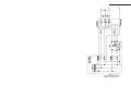
BPS Series Bypass Switch
BPT Series Bypass Transformer
FOR CFR UNINTERRUPTIBLE POWER SUPPLIES
CANADA
Alpha Technologies
5700 Sidley Street
Burnaby, B.C. V5J 5E5
Tel: (604) 430-1476
FAX: (604) 430-8908
TECHNOLOGIES
UNITED STATES
Alpha Technologies
3767 Alpha Way
Bellingham, WA 98226
Tel: (360) 647-2360
FAX: (360) 671-4936
ALPHA
Operator's Manual
UNITED KINGDOM
Alpha Technologies
Cartel Business Estate
Edinburgh Way
Harlow, Essex CM20 2DU
Tel: +44-1279-422110
FAX: +44-21279-423355
FROM ALPHA TECHNOLOGIES
GERMANY
Alpha Technologies
Hansastrasse 8
D-91126 Schwabach
Tel: 49-9122-997303
FAX: 49-9122-997321
MIDDLE EAST
Alphatec
P.O. Box 6468
3307 Limassol, Cyprus
Tel: +357-5-375675
FAX: +357-5-359595
TECHNOLOGIES
ALPHA
Operator's Manual
BPS Series Bypass Switch
BPT Series Bypass Transformer
FOR CFR UNINTERRUPTIBLE POWER SUPPLIES
©1995 Alpha Technologies
020-133-B0 03/95
THE ALPHA BPS SERIES
6. MAINTENANCE
IMPORTANT SAFETY PRECAUTIONS
CAUTION: Before attempting to install either the Bypass Switch or the Bypass Transformer please read the instructions contained in this manual. It provides information on
how to install and test bypass switches in North America and some foreign countries. If in
doubt, contact Alpha Technologies for assistance.
Since there are many possible voltages, voltage combinations and configurations
possible throughout the world, only the more common ones are described in this
manual.
6.1
Repair Instructions
Before returning a unit to Alpha Technologies for repair, a Return Material Authorization (RMA) should first be obtained from Alpha's Customer Service Department. The
RMA number should be clearly marked on the unit’s original shipping container. If the
original container is no longer available, the UPS should be packed with at least 3 inches
of shock-absorbent material. Note: Do not use popcorn-type packing material. Returns
should be prepaid and insured (COD and freight collect can not be accepted).
ALPHA TECHNOLOGIES DOES NOT ASSUME RESPONSIBILITY FOR DAMAGE
CAUSED BY THE IMPROPER PACKAGING OF RETURNED UNITS.
If you have an installation configuration that is not described in this manual
contact Alpha for assistance.
Before proceeding, you should read this manual and be sure you understand its
intent.
For parts and service, contact the Alpha Technologies Customer Service Department at:
For safety reasons the installation must be carried out by qualified personnel.
Do not discard this manual. It should be kept with the UPS and the Bypass
Switch. Should the UPS ever need to be removed or physically disconnected for
service, or relocated, the installation testing procedure (section 3.1) MUST be
performed again BEFORE the bypass switch is operated.
United States
Canada
United Kingdom
Germany
Middle East
(360) 647-2360
(604) 430-1476
44-1279-422110
49-9122- 997303
357-5-375675
* Effective 1/95, area code 206 was changed to 360.
TO OBTAIN COMPLETE TECHNICAL SUPPORT
(7 DAYS / WEEK, 24 HOURS / DAY)
CALL
1-800-322-5742
(USA)
1-800-667-8743
(Canada)
23
6. MAINTENANCE
6.2
Warranty
IMPORTANT SAFETY INSTRUCTIONS
CONTAINED IN THIS MANUAL
LIMITED WARRANTY
Alpha Technologies warrants its equipment to be free of manufacturing defects in material
and workmanship for a period of 24 months from the date of manufacture. The liability of
Alpha Technologies under this warranty is solely limited to repairing, replacing, or issuing
credit (at the discretion of Alpha Technologies) provided that:
1.
2.
3.
4.
Alpha Technologies is promptly notified in writing, or by telephone, that a failure
or defect has occurred;
A Return Authorization number is obtained and clearly marked on the outside
of the shipping container;
Customer is responsible for all shipping and handling charges (COD and freight
collect will not be accepted without prior approval from Alpha Technologies);
The service engineer’s examination of the returned unit shall disclose, to his
satisfaction, that such defects have not been caused by misuse, neglect,
improper installation, repair, alteration, or accident. If Alpha Technologies does
determine that the unit has been damaged due to one of these causes, or if the
unit is free of defects, a handling or repair fee will be necessary prior to returning
the unit.
THIS ONE-YEAR WARRANTY IS IN LIEU OF ALL OTHER WARRANTIES, EXPRESSED
OR IMPLIED, INCLUDING, BUT NOT LIMITED TO, IMPLIED WARRANTIES OF
MERCHANTABILITY AND FITNESS FOR A PARTICULAR PURPOSE.
IN NO CASE SHALL ALPHA TECHNOLOGIES BE LIABLE FOR ANY CONSEQUENTIAL
DAMAGES FOR BREACH OF THIS OR ANY OTHER WARRANTY, EXPRESSED OR
IMPLIED, WHATSOEVER.
ANY ACTION FOR BREACH OF THIS LIMITED ONE-YEAR WARRANTY MUST BE
BROUGHT WITHIN A PERIOD OF 12 MONTHS FROM DATE OF PURCHASE.
CAUTION
RISK OF ELECTRICAL SHOCK
CAUTION: TO REDUCE THE RISK OF ELECTRICAL
SHOCK, AND ENSURE THE SAFE OPERATION OF THIS
UNIT, THE FOLLOWING SYMBOLS HAVE BEEN PLACED
THROUGHOUT THE MANUAL. WHERE THESE SYMBOLS
APPEAR, SERVICING SHOULD BE PERFORMED ONLY BY
QUALIFIED PERSONNEL.
DANGEROUS VOLTAGE
A DANGEROUS VOLTAGE EXISTS IN THIS AREA OF THE
POWER SUPPLY. USE EXTREME CAUTION.
ATTENTION
IMPORTANT OPERATING INSTRUCTIONS. THIS PROCEDURE SHOULD BE PERFORMED ONLY BY QUALIFIED SERVICE PERSONNEL.
Alpha Technologies reserves the right to discontinue particular models and to make
modifications in design and/or function at any time, without notice and without incurring
obligations to modify previously purchased units.
U.S.A.
3767 Alpha Way
Bellingham, WA 98226
(360) 647-2360
FAX: (360) 671-4936
ALPHA
TECHNOLOGIES
24
Canada
5700 Sidley Street
Burnaby, B.C. V5J 5E5
(604) 430-1476
FAX: (604) 430-8908
SAVE THESE INSTRUCTIONS
5. SCHEMATIC DIAGRAMS
The Alpha BPS SERIES
Table of Contents
The Alpha Bypass Switch and Bypass Transformer
1.
INTRODUCTION
1.1
1.2
1.3
1.4
The Alpha Bypass Switch
The Alpha Bypass Transformer
Bypass Switch Terminology
Bypass Selection Guide
2.
INSTALLATION
2.2
2.1 Unpacking and Inspection
Bypass Switch Installation
2.3 Circuit Breaker Rating and Wire Gauge
3.
OPERATION
3.2
3.1 Testing Bypass Switch Operation
Bypass Switch Operating Procedure
4.
SPECIFICATIONS
4.1
4.2
5.
6.
BPS Specifications
BPT Specifications
4
5
6
7
8
9
10
SCHEMATIC DIAGRAMS
120V IN, 120V OUT (Figure 1)
120V IN, 120V/208V OUT (Figure 2)
120V IN, 120V/240V OUT (Figure 3)
208V IN, 120V OUT (Figure 4)
208V IN, 120V OUT (Figure 5)
208V IN, 120V/208V OUT (Figure 6)
208V IN, 120V/208V OUT (Figure 7)
208V IN, 110V/240V OUT (Figure 8)
240V IN, 120V OUT (Figure 9)
240V IN, 120V/208V OUT (Figure 10)
240V IN, 120V/240V OUT (Figure 11)
230V IN, 230V OUT (Figure 12)
11
12
13
14
15
16
17
18
19
20
21
22
MAINTENANCE
6.1 Repair Instructions
6.2 Warranty
23
24
Figure 12.
System Bypass Schematic
230V IN - 230V OUT
22
1
1
1
3
i
1. INTRODUCTION
5. SCHEMATIC DIAGRAMS
1.1 The Alpha Bypass Switch (BPS)
The Bypass Switch is a manually operated mechanical switch which is used to select
an alternate source of power for critical loads should the UPS require service or maintenance. Normally the output to the critical load is powered by the UPS and the Bypass
Switch is in the UPS position. If however, the UPS is taken off-line for service or maintenance, the Bypass Switch can be switched to the Bypass position and the critical loads
can still receive power directly from the utility supply. There are two types of Bypass
Switches available: Make Before Break (MBB) and Break Before Make (BBM). These will
be described later in this manual.
1.2 The Alpha Bypass Transformer (BPT)
Number of Poles
The number of poles in a given switch refers to the number of sets of contacts
available. A 2-pole switch, for example, has two sets of contacts and can therefore be
used to break or make each side of a single voltage system. A single pole type switch is
shown in Illustration 1.
Each set of contacts (poles) in the bypass switch will pass 1 of 2 signals through to a
common line (COM). The contacts on each pole change positions together since they
share a common operating shaft connected to the switch knob (Indicated schematically by
a dotted line through the switch contacts. See figures 1 through 10 at the end of this
manual.
Changeover Contacts
Each pole in the bypass switch comprises a set of changeover contacts. These
contacts selects one of two signals (Bypass or UPS) and passes it through to a common
line (COM). Refer to Illustration 1 below, the mechanical arm connects the bypass line
(contact A) to the common side of the switch.
When the switch position is changed to select the UPS output, the mechanical arm
switches over to the UPS side of the switch. With contact B now connected to the
common, the UPS supply appears on the LOAD side of the switch.
Mechanical arm
2.
3.
NOTES:
1.
NOTE 1
The UPS will be internally configured for either 208V or 240V output.
Check the nameplate rating of the UPS to verify the correct voltage.
Omit this connection if 120V output is not required or available.
Terminal designations are shown for Standard VBPT Series.
If BPT -S Series transformer is used, refer to label on
transformer for actual terminal designations.
1.3 Bypass Switch Terminology
NOTE 3
NOTE 2
NOTE 2
The Bypass Transformer contains an Isolation transformer and is used in combination
with the Bypass Switch to provide utility isolation when the UPS is taken out of service.
Using the BPT the critical load is isolated from the utility power.
Bypass
UPS
A
COM
B
Load side of switch
Figure 10.
System Bypass Schematic
240V IN - 120V/208V OUT
Illustration 1.
Single Pole Switchover Diagram
20
1
1. INTRODUCTION
5. SCHEMATIC DIAGRAMS
1.3 Bypass Switch Terminology, continued
Make-Before-Break
Make-Before-Break Bypass Switches provide continuous power to the load during
switching. The bypass supply and the UPS output supply are momentarily connected in
parallel to ensure that power to the load is not interrupted when switching. The duration of
time the two supplies remain in parallel is determined by how quickly the switch is
operated. The switch should always be operated in a quick continuous motion to ensure
reliable operation of the switch and continuous undisturbed power to the load.
Break-Before-Make
Break-Before-Make Bypass Switches ensures a break in power to the loads during
switching. The bypass supply and the UPS output supply are never connected in parallel
during the switching process. This ensures there is a break in supply voltage to the
output side of the switch. The duration of the break is determined by how quickly the
switch is operated. Operation of the switch should be quick and decisive to ensure safe
and reliable operation of the switch while minimizing the duration of the break to the load.
The break-before-make type of Bypass Switch ensures for safe operation, especially if the
UPS output voltage and the Bypass supply are out of phase.
CAUTION: Please consult Table 1 Bypass Switch Selection Guide and the schematic
diagrams at the end of the manual for selecting the proper type of Bypass Switch for your
application. The model type number designation is derived according to the definition
below.
Bypass Switch
B P S 2M 3 P
Maximum Current Rating
1 - 40 Amps
2 - 80 Amps
Type of Switch
M - Make Before Break
B - Break Before Make
Number of poles
Bypass Transformer
B P T 3000 - S
VA rating
Provides only 208V Input and
240V Output. The S models
cannot be used for 208V Output, but delivery may be available on short notice.
Model Number Identification
Figure 9.
System Bypass Schematic
240V IN - 120V OUT
2
19
18
Figure 8.
System Bypass Schematic
208V IN - 120V/240V OUT
3
120V
120V / 208V
120V /240V
120V
120 / 208V
120 / 240V
120V
120 / 208V
120 / 240V
230V 50 Hz
120V
120V
120V
208V
208V
208V
240V
240V
240V
230V
BPS 2M3P
Fig. 12
BPS 2M3P
Fig. 11
BPS 2B3P
Fig. 12
BPS 2B3P
Fig. 11
BPS 2B3P
BPT 3000
Fig. 7
BPT 3000
Fig. 7
BPS 2B3P
Fig. 9
BPS 2M3P
BPS 2M3P
Fig. 9
BPS 2B3P
BPT 3000-S or
BPT 3000
Fig. 8
Fig. 6
BPT 3000
Fig. 7
BPS 2M3P
BPT 3000-S or
BPT 3000
Fig. 8
BPS 2B3P
Fig. 4
BPS 2B3P
BPS2B3P
Fig. 3
BPS 2B3P
Fig. 2
BPS 2M3P
BPS 2M3P
BPT 3000-S or
BPT 3000
Fig. 5
BPS2M3P
Fig. 3
BPS 2M3P
Fig. 2
BPS 2B3P
Fig. 1
BPS 2M3P
BBM
Fig. 1
MBB
CFR 3000
or smaller
Bypass Switches
BPS 2M3P 020-135-21
BPS2B3P 020-136-21
BPT
BPT
BPT
BPT
BPT
3000-S
5000-S
7500-S
10K-S
15K-S
242-129-10
242-130-10
242-131-10
242-135-10
242-205-10
Bypass Transformers
BPT 3000
242-152-10
BPT 5000
242-153-10
BPT 7500
242-154-10
BPT 10K
242-155-10
BPT 15K
242-156-10
BPS 2M3P
Fig. 12
BPS 2M3P
Fig. 11
BPT 7500
Fig. 7
BPS 2M3P
BPS 2M3P
Fig. 9
BPS 2M3P
BPT 7500-S or
BPT 7500
Fig. 8
BPT 7500
Fig. 7
BPS 2M3P
N/A
N/A
N/A
N/A
MBB
BPS 2B3P
Fig. 12
BPS 2B3P
Fig. 11
BPT 7500
Fig. 7
BPS 2B3P
BPS 2B3P
Fig. 9
BPS 2B3P
BPT 7500-S or
BPT 7500
Fig. 8
Fig. 6
BPS 2B3P
BBM
BPS 2M3P
Fig. 12
BPS 2M3P
Fig. 11
BPT 10K
Fig. 7
BPS 2M3P
BPS 2M3P
Fig. 9
BPS 2M3P
BPT 10K-S or
BPT 10K
Fig. 8
BPT 10K
Fig. 7
BPS 2M3P
Fig. 12
BPS 2B3P
Fig. 11
BPT 10K
Fig. 7
BPS 2B3P
BPS 2B3P
Fig. 9
BPS 2B3P
BPT 10K-S or
BPT 10K
Fig. 8
Fig. 6
BPS 2B3P
BBM
CFR 10K
BPS 2M3P
N/A
N/A
N/A
N/A
MBB
2
2
BPS 2M3P
Fig. 12
BPS 2M3P
Fig. 11
BPT 15K
Fig. 7
BPS 2M3P
BPS 2M3P
Fig. 9
BPS 2M3P
BPT 15K-S or
BPT 15K
Fig. 8
BPT 15K
Fig. 7
BPS 2M3P
N/A
N/A
N/A
N/A
MBB
BPS 2M3P
Fig. 12
BPS 2B3P
Fig. 11
BPT 15K
Fig. 7
BPS 2B3P
BPS 2B3P
Fig. 9
BPS 2B3P
BPT 15K-S or
BPT 15K
Fig. 8
Fig. 6
BPS 2B3P
BBM
CFR 15K
Explanation of bypass Switch ordering code:
BPS xyzz
x = 1 : 40 Amp contact rating
x = 2 : 80 Amp contact rating
y = M : Make-Before-Break contacts
y = B : Break-Before-Make contacts
zz = 3P : 3 pole switch
Reference to Figure indicated applicable connection diagram
N/A
indicates the configuration is not available for this model of UPS
MBB
Make Before Break Switch (Provides uninterrupted transfer)
BBM
Break Before Make Switch (Output will be interrupted for at least 30 milliseconds)
Selection guide for Bypass Switch systems
The bypass system consists of the bypass switch (BPS) and bypass transformer if required (BPT)
BPS 2B3P
Fig. 12
BPS 2B3P
Fig. 11
BPT 5000
Fig. 7
BPS 2B3P
BPS 2B3P
Fig. 9
BPS 2B3P
BPT 5000-S or
BPT 5000
Fig. 8
Fig. 6
BPS 2B3P
Fig. 4
BPS 2B3P
BPS2B3P
Fig . 3
BPS 2B3P
Fig. 2
Fig. 1
BPS 2B3P
BBM
CFR 7.5K
Table 1. Bypass Model Selection Guide
BPS 1M2P
Fig. 12
BPS 2M3P
Fig. 11
BPT 5000
Fig. 7
BPS 2M3P
BPS 2M3P
Fig. 9
BPS 2M3P
BPT 5000-S or
BPT 5000
Fig. 8
BPT 5000
Fig. 7
BPS 2M3P
BPS 2M3P
BPT5000-S or
BPT 5000
Fig. 5
BPS2M3P
Fig. 3
BPS 2M3P
Fig. 2
Fig. 1
BPS 2M3P
MBB
CFR 5000
or CFR 4000
The UPS will be internally configured for either 208V or 240V output.
Check the nameplate rating of the UPS to verify the correct voltage.
Omit this connection if 120V output is not required or available.
Terminal designations are shown for Standard BPT Series.
If BPT -S Series transformer is used, refer to label on
transformer for actual terminal designations.
Alpha part numbers for components listed above:
Output
Input
Configuration
2.
3.
NOTES:
1.
1
NOTE 3
5. SCHEMATIC DIAGRAMS
1. INTRODUCTION
1.4 Bypass Model Selection Guide
2. INSTALLATION
5. SCHEMATIC DIAGRAMS
2.1 Unpacking and Inspection
Carefully inspect the contents while removing them from the shipping container. If
items appear damaged or are missing, contact Alpha Technologies and the shipping
company immediately. Most shipping companies have only a short claim period. Make
sure the following items have been included:
1. Bypass Switch and/or a Bypass Transformer
2. Operator’s Manual
3. Any other ordered options
1
Options
Purchase Date
THIS UNIT WAS PURCHASED FROM:
NOTES:
1.
Dealer Name
City
State / Province
ZIP / Postal Code
Country
Telephone #
Figure 7.
System Bypass Schematic
208V IN - 120V/208V OUT
4
17
2.
3.
2
Model
Serial #
The UPS will be internally configured for either 208V or 240V output.
Check the nameplate rating of the UPS to verify the correct voltage.
Omit this connection if 120V output is not required or available.
Terminal designations are shown for Standard VBPT Series.
If BPT -S Series transformer is used, refer to label on
transformer for actual terminal designations.
COMPLETE THE FOLLOWING FOR YOUR RECORDS:
NOTE 3
PLEASE READ THE OPERATOR'S MANUAL.
Become familiar with the BPS and/or BPT and its components. Review the drawings
and illustrations contained in this manual before proceeding with the installation. If you
have questions regarding the safe installation or operation of this system, contact Alpha
Technologies.
2
SAVE THE ORIGINAL SHIPPING CONTAINER.
In the event a component needs to be returned for service, it should be packaged in
its original shipping container. If the original container is not available, make sure the unit
is packed with at least three inches of shock-absorbing material to prevent shipping
damage. Note: Do not use popcorn-type material. Alpha Technologies is not responsible
for damage caused by improper packaging on returned units.
5. SCHEMATIC DIAGRAMS
2. INSTALLATION
2.2 Bypass Switch Installation
CAUTION: The installation and testing of the Bypass Switch must be performed only by
qualified personnel familiar with installing electrical equipment. This must be done in
accordance with the rules and regulations of local and national electrical codes.
The installation of a bypass circuit breaker is required. To select the proper size
circuit breaker refer to Table 2.
Procedure:
1. Select an appropriate location for the Bypass Switch (and Bypass Transformer if
required). The Bypass Switch can be mounted to a wall close to the UPS. The Bypass
Transformer can be either wall or floor mounted.
2. Connect the BPS (and BPT if required) to the UPS and utility following the schematic wiring diagram applicapable to your configuration as specified in Table 1. Refer
also to Table 2 to select the proper size circuit breaker and wire gauge.
2.
NOTES:
1.
The UPS will be internally configured for either 208V or 240V.
Check the nameplate rating of the UPS to verify the correct voltage.
Omit this connection if 120V output is not required or available.
3. Before placing the BPS-UPS into service, perform the test procedure outlined in
section 3.1 of this manual. It is important that both sources of power are “in phase” to
provide trouble free Bypass Switch operation.
SYSTEMS WITHOUT
BYPASS
TRANSFORMER
UPS
MODEL
Max. UPS Bypass
Output
CB
Current
Rating
CFR 1500
(or smaller)
CFR 2000
CFR 2500
CFR 3000
CFR 4000
CFR 5000
CFR 7.5K
CFR 10K
CFR 15K
Wire Size
SYSTEMS WITH
BYPASS TRANSFORMER
Input
Bypass Wire Size for
Rating
CB
208VAC or
of BPT Rating 240VAC Load
at
208VAC
12.5A
15A
#14 AWG
8A
15A
#14 AWG
#14 AWG
17A
21A
25A
33A
41A
36A
48A
72A
20A
30A
40A
50A
60A
50A
60A
90A
#12 AWG
#10 AWG
#8 AWG
#6 AWG
#6 AWG
#6 AWG
#6 AWG
#3 AWG
11A
13A
16A
21A
27A
40A
53A
80A
15A
15A
20A
30A
40A
50A
70A
100A
#14 AWG
#14 AWG
#12 AWG
#10 AWG
#8 AWG
#6 AWG
#4 AWG
#3 AWG
#12 AWG
#10 AWG
#8 AWG
#6 AWG
#6 AWG
n/a
n/a
n/a
Table 2.
Bypass Circuit Breaker current rating.
Current ratings for CFR 5000 and smaller units are based on 120V rated output.
This is because the rated output of L1 is capable of supplying the full 120V current.
Current ratings for CFR 7.5K - 15K are based on the maximum current rating for L1 and
L2 combined (refer to the appropriate Operator’s Manual for further details).
Wire sizes are based on three current carrying copper conductors rated at 75 deg. C and
are guidelines only. Always follow your local electrical code.
Figure 6.
System Bypass Schematic
208V IN - 120V/208V OUT
16
Wire Size for
120VAC Load
5
2. INSTALLATION
5. SCHEMATIC DIAGRAMS
2.3 Circuit Breaker Rating and Wire Gauge
Systems with a Bypass Isolation Transformer Installed:
Install a Bypass Circuit Breaker with the current rating specified in Table 2. Use the
wire gauge, as specified, for all connections to the Bypass Switch, especially if there is
208V or 240V supplied to the load.
CAUTION: For UPS output configurations which supply both 120V and 208 / 240V loads,
care must be taken not to overload either of the output windings of the Bypass Transformer. The maximum current of each output winding is limited to the current rating at
208V (i.e., the maximum current rating for L1 or L2 is the VA rating of the transformer
divided by 208). Although CFR models up to 5000 VA are capable of supplying the full
rated power at 120V from L1, systems with a bypass transformer must have the 120V
loads split between L1 and L2. For CFR models 7.5K and greater the Bypass Transformer
rating is the same as the UPS output rating. Refer to the CFR Operator’s Manual for a
complete description on Load Sharing.
NOTES:
1.
Terminal designatioons are shown for Standard BPT Series
Bypass transformers.
If BPT -S Series trandformers are used, refer to label on
transformer for actual terminal designations.
NOTE 1
Without Bypass Isolation Transformer Installed:
Install a Bypass Circuit Breaker with a current rating shown in Table 2. Use the wire
size specified for all connections to the Bypass Switch.
Figure 5.
System Bypass Schematic
208V IN - 120V OUT
6
15
5. SCHEMATIC DIAGRAMS
3. OPERATION
3.1 Testing Bypass Switch Operation
CAUTION: This test must first be performed with all power to the Bypass Switch turned
OFF.
To test that all connections are made correctly, with all power to the bypass switch
turned off, measure the resistance between pin 2 & 3, 5 & 7, and between 9 & 11 to
ensure that there is no connection between the two sources of power (UPS and BYPASS). Then turn the switch to the BYPASS position and turn the UPS and the bypass
circuit breaker ON so that power from both sources is available at the bypass switch.
Verify the following voltages shown in the Table below.
Voltage Check:
Measuring Points
Ground to Neutral
Ground to L1
Ground to L2
(GND to pin 5/7 of BPS )
(GND to pin 1/3 of BPS )
(GND to pin 9/11 of BPS )
Phase Check:
L1, UPS - BYPASS
N, UPS - BYPASS
L2, UPS - BYPASS
Measured Voltages
Measuring Points
<5V
110 - 125 V
110 - 130 V if 240 V system
75 - 95 V if 208 V system
Make-BeforeBreak Bypass
Switch
(pin 2 to pin 4 of BPS)
(pin 6 to pin 8 of BPS)
(pin 10 to pin 12 of BPS)
< 20 V
< 20 V
< 20 V
Break-BeforeMake Bypass
Switch
< 100 V
< 20 V
< 100 V
Table 3.
BPS Voltages Phase Checks
DO NOT OPERATE THE SWITCH IF THE MEASURED VOLTAGES ARE GREATER
THAN SHOWN IN THE TABLE ABOVE.
If you cannot obtain the indicated voltages, check your wire connections. For example, is L1 of the UPS input connected to the same phase as L1 of the bypass line? Also
check the input and output voltages of the UPS and / or the Bypass Transformer as
shown in Table 4. Contact ALPHA if the phasing is not correct or if you need further
assistance.
UPS or BPT
Figure 4.
System Bypass Schematic
208V IN - 120V OUT
14
Measuring Points
Correct
Phasing
Out of Phase
CFR with 120 Volt input
input L1 to output L1
input L2 to output L1
< 30 V
> 180 V
> 180 V
< 30 V
CFR with 208 or 240 V input
input L1 to output L1
input L2 to output L1
< 100 V
> 180 V
> 180 V
< 100 V
Bypass Transformer
H1 to X1
H1 to X5
< 100 V
> 200 V
> 200 V
< 100 V
Table 4.
UPS / BPT Voltage and Phase Checks
(All measurements are at no load)
7
5. SCHEMATIC DIAGRAMS
3. OPERATION
Always operate the switch with a quick continuous motion, do not hold it in midposition.
•
DO NOT operate the bypass switch while the UPS is in inverter mode (LINE FAILURE light on the front panel will be ON).
NOTES:
1.
Bypass Switch - Closed
Bypass Switch - Open
Figure 3.
System Bypass Schematic
120V IN - 120V/240V OUT
8
13
2.
•
The UPS will be internally configured for either 208V or 240V.
Check the nameplate rating of the UPS to verify the correct voltage.
Omit this connection if 120V output is not required or available.
3.2 Bypass Switch Operating Procedure
5. SCHEMATIC DIAGRAMS
4.0 SPECIFICATIONS
MODEL
A
B
C
D
E
F
G
2M3P, 2B3P (inches)
(mm)
10.5
266
12
304
9.1
231
2
50
2
50
2
50
1.5
38
Bypass Switch Dimensions
NOTES:
1.
The UPS will be internally configured for either 208V or 240V.
Check the nameplate rating of the UPS to verify the correct voltage.
4.1 BPS Specifications
Figure 2.
System Bypass Schematic
120V IN - 120V/208V OUT
12
9
KNOCK
OUT
5. SCHEMATIC DIAGRAMS
4.0 SPECIFICATIONS
4.2 MBT Specifications
Bypass Transformer - Closed
Bypass Transformer - Open
BYPASS TRANSFORMER MECHANICAL AND ELECTRICAL SPECIFICATIONS
MODEL
HxWxD
BPT
BPT
BPT
BPT
BPT
10”x14”x10”
15”x16”x12”
15”x16”x12”
24”x24”x18”
24”x24”x18”
3000
5000
7500
10K
15K
Regulation:
Frequency:
Approval:
Ambient Temperature:
Insulation Class:
Acoustic noise:
Mounting:
(254x356x254mm)
(381x406x284mm)
(381x406x305mm)
(610x610x457mm)
(610x610x457mm)
Weight
Eff.
Heat Output
62 lbs (28kg)
80 lbs (36kg)
100 lbs (45kg)
120 lbs (54kg)
160 lbs (73kg)
91%
91%
92%
93%
94%
255W,
490W,
615W,
770W,
910W,
approximately 7% (depending on model)
60Hz
UL listed, CSA
0-40oC
220oC
<45 dBa
Floor or wall
NOTE: Size and dimensions are approximate.
Specifications are subject to change without notice.
10
870 BTU/hr
1670 BTU/hr
2100 BTU/hr
2630 BTU/hr
3100 BTU/hr
Figure 1.
System Bypass Schematic
120V IN - 120V OUT
11
5. SCHEMATIC DIAGRAMS
4.0 SPECIFICATIONS
MODEL
A
B
C
D
E
F
G
2M3P, 2B3P (inches)
(mm)
10.5
266
12
304
9.1
231
2
50
2
50
2
50
1.5
38
Bypass Switch Dimensions
NOTES:
1.
The UPS will be internally configured for either 208V or 240V.
Check the nameplate rating of the UPS to verify the correct voltage.
4.1 BPS Specifications
Figure 2.
System Bypass Schematic
120V IN - 120V/208V OUT
12
9
KNOCK
OUT
5. SCHEMATIC DIAGRAMS
3. OPERATION
Always operate the switch with a quick continuous motion, do not hold it in midposition.
•
DO NOT operate the bypass switch while the UPS is in inverter mode (LINE FAILURE light on the front panel will be ON).
NOTES:
1.
Bypass Switch - Closed
Bypass Switch - Open
Figure 3.
System Bypass Schematic
120V IN - 120V/240V OUT
8
13
2.
•
The UPS will be internally configured for either 208V or 240V.
Check the nameplate rating of the UPS to verify the correct voltage.
Omit this connection if 120V output is not required or available.
3.2 Bypass Switch Operating Procedure
5. SCHEMATIC DIAGRAMS
3. OPERATION
3.1 Testing Bypass Switch Operation
CAUTION: This test must first be performed with all power to the Bypass Switch turned
OFF.
To test that all connections are made correctly, with all power to the bypass switch
turned off, measure the resistance between pin 2 & 3, 5 & 7, and between 9 & 11 to
ensure that there is no connection between the two sources of power (UPS and BYPASS). Then turn the switch to the BYPASS position and turn the UPS and the bypass
circuit breaker ON so that power from both sources is available at the bypass switch.
Verify the following voltages shown in the Table below.
Voltage Check:
Measuring Points
Ground to Neutral
Ground to L1
Ground to L2
(GND to pin 5/7 of BPS )
(GND to pin 1/3 of BPS )
(GND to pin 9/11 of BPS )
Phase Check:
L1, UPS - BYPASS
N, UPS - BYPASS
L2, UPS - BYPASS
Measured Voltages
Measuring Points
<5V
110 - 125 V
110 - 130 V if 240 V system
75 - 95 V if 208 V system
Make-BeforeBreak Bypass
Switch
(pin 2 to pin 4 of BPS)
(pin 6 to pin 8 of BPS)
(pin 10 to pin 12 of BPS)
< 20 V
< 20 V
< 20 V
Break-BeforeMake Bypass
Switch
< 100 V
< 20 V
< 100 V
Table 3.
BPS Voltages Phase Checks
DO NOT OPERATE THE SWITCH IF THE MEASURED VOLTAGES ARE GREATER
THAN SHOWN IN THE TABLE ABOVE.
If you cannot obtain the indicated voltages, check your wire connections. For example, is L1 of the UPS input connected to the same phase as L1 of the bypass line? Also
check the input and output voltages of the UPS and / or the Bypass Transformer as
shown in Table 4. Contact ALPHA if the phasing is not correct or if you need further
assistance.
UPS or BPT
Figure 4.
System Bypass Schematic
208V IN - 120V OUT
14
Measuring Points
Correct
Phasing
Out of Phase
CFR with 120 Volt input
input L1 to output L1
input L2 to output L1
< 30 V
> 180 V
> 180 V
< 30 V
CFR with 208 or 240 V input
input L1 to output L1
input L2 to output L1
< 100 V
> 180 V
> 180 V
< 100 V
Bypass Transformer
H1 to X1
H1 to X5
< 100 V
> 200 V
> 200 V
< 100 V
Table 4.
UPS / BPT Voltage and Phase Checks
(All measurements are at no load)
7
2. INSTALLATION
5. SCHEMATIC DIAGRAMS
2.3 Circuit Breaker Rating and Wire Gauge
Systems with a Bypass Isolation Transformer Installed:
Install a Bypass Circuit Breaker with the current rating specified in Table 2. Use the
wire gauge, as specified, for all connections to the Bypass Switch, especially if there is
208V or 240V supplied to the load.
CAUTION: For UPS output configurations which supply both 120V and 208 / 240V loads,
care must be taken not to overload either of the output windings of the Bypass Transformer. The maximum current of each output winding is limited to the current rating at
208V (i.e., the maximum current rating for L1 or L2 is the VA rating of the transformer
divided by 208). Although CFR models up to 5000 VA are capable of supplying the full
rated power at 120V from L1, systems with a bypass transformer must have the 120V
loads split between L1 and L2. For CFR models 7.5K and greater the Bypass Transformer
rating is the same as the UPS output rating. Refer to the CFR Operator’s Manual for a
complete description on Load Sharing.
NOTES:
1.
Terminal designatioons are shown for Standard BPT Series
Bypass transformers.
If BPT -S Series trandformers are used, refer to label on
transformer for actual terminal designations.
NOTE 1
Without Bypass Isolation Transformer Installed:
Install a Bypass Circuit Breaker with a current rating shown in Table 2. Use the wire
size specified for all connections to the Bypass Switch.
Figure 5.
System Bypass Schematic
208V IN - 120V OUT
6
15
5. SCHEMATIC DIAGRAMS
2. INSTALLATION
2.2 Bypass Switch Installation
CAUTION: The installation and testing of the Bypass Switch must be performed only by
qualified personnel familiar with installing electrical equipment. This must be done in
accordance with the rules and regulations of local and national electrical codes.
The installation of a bypass circuit breaker is required. To select the proper size
circuit breaker refer to Table 2.
Procedure:
1. Select an appropriate location for the Bypass Switch (and Bypass Transformer if
required). The Bypass Switch can be mounted to a wall close to the UPS. The Bypass
Transformer can be either wall or floor mounted.
2. Connect the BPS (and BPT if required) to the UPS and utility following the schematic wiring diagram applicapable to your configuration as specified in Table 1. Refer
also to Table 2 to select the proper size circuit breaker and wire gauge.
2.
NOTES:
1.
The UPS will be internally configured for either 208V or 240V.
Check the nameplate rating of the UPS to verify the correct voltage.
Omit this connection if 120V output is not required or available.
3. Before placing the BPS-UPS into service, perform the test procedure outlined in
section 3.1 of this manual. It is important that both sources of power are “in phase” to
provide trouble free Bypass Switch operation.
SYSTEMS WITHOUT
BYPASS
TRANSFORMER
UPS
MODEL
Max. UPS Bypass
Output
CB
Current
Rating
CFR 1500
(or smaller)
CFR 2000
CFR 2500
CFR 3000
CFR 4000
CFR 5000
CFR 7.5K
CFR 10K
CFR 15K
Wire Size
SYSTEMS WITH
BYPASS TRANSFORMER
Input
Bypass Wire Size for
Rating
CB
208VAC or
of BPT Rating 240VAC Load
at
208VAC
12.5A
15A
#14 AWG
8A
15A
#14 AWG
#14 AWG
17A
21A
25A
33A
41A
36A
48A
72A
20A
30A
40A
50A
60A
50A
60A
90A
#12 AWG
#10 AWG
#8 AWG
#6 AWG
#6 AWG
#6 AWG
#6 AWG
#3 AWG
11A
13A
16A
21A
27A
40A
53A
80A
15A
15A
20A
30A
40A
50A
70A
100A
#14 AWG
#14 AWG
#12 AWG
#10 AWG
#8 AWG
#6 AWG
#4 AWG
#3 AWG
#12 AWG
#10 AWG
#8 AWG
#6 AWG
#6 AWG
n/a
n/a
n/a
Table 2.
Bypass Circuit Breaker current rating.
Current ratings for CFR 5000 and smaller units are based on 120V rated output.
This is because the rated output of L1 is capable of supplying the full 120V current.
Current ratings for CFR 7.5K - 15K are based on the maximum current rating for L1 and
L2 combined (refer to the appropriate Operator’s Manual for further details).
Wire sizes are based on three current carrying copper conductors rated at 75 deg. C and
are guidelines only. Always follow your local electrical code.
Figure 6.
System Bypass Schematic
208V IN - 120V/208V OUT
16
Wire Size for
120VAC Load
5
2. INSTALLATION
5. SCHEMATIC DIAGRAMS
2.1 Unpacking and Inspection
Carefully inspect the contents while removing them from the shipping container. If
items appear damaged or are missing, contact Alpha Technologies and the shipping
company immediately. Most shipping companies have only a short claim period. Make
sure the following items have been included:
1. Bypass Switch and/or a Bypass Transformer
2. Operator’s Manual
3. Any other ordered options
1
Options
Purchase Date
THIS UNIT WAS PURCHASED FROM:
NOTES:
1.
Dealer Name
City
State / Province
ZIP / Postal Code
Country
Telephone #
Figure 7.
System Bypass Schematic
208V IN - 120V/208V OUT
4
17
2.
3.
2
Model
Serial #
The UPS will be internally configured for either 208V or 240V output.
Check the nameplate rating of the UPS to verify the correct voltage.
Omit this connection if 120V output is not required or available.
Terminal designations are shown for Standard VBPT Series.
If BPT -S Series transformer is used, refer to label on
transformer for actual terminal designations.
COMPLETE THE FOLLOWING FOR YOUR RECORDS:
NOTE 3
PLEASE READ THE OPERATOR'S MANUAL.
Become familiar with the BPS and/or BPT and its components. Review the drawings
and illustrations contained in this manual before proceeding with the installation. If you
have questions regarding the safe installation or operation of this system, contact Alpha
Technologies.
2
SAVE THE ORIGINAL SHIPPING CONTAINER.
In the event a component needs to be returned for service, it should be packaged in
its original shipping container. If the original container is not available, make sure the unit
is packed with at least three inches of shock-absorbing material to prevent shipping
damage. Note: Do not use popcorn-type material. Alpha Technologies is not responsible
for damage caused by improper packaging on returned units.
18
Figure 8.
System Bypass Schematic
208V IN - 120V/240V OUT
3
120V
120V / 208V
120V /240V
120V
120 / 208V
120 / 240V
120V
120 / 208V
120 / 240V
230V 50 Hz
120V
120V
120V
208V
208V
208V
240V
240V
240V
230V
BPS 2M3P
Fig. 12
BPS 2M3P
Fig. 11
BPS 2B3P
Fig. 12
BPS 2B3P
Fig. 11
BPS 2B3P
BPT 3000
Fig. 7
BPT 3000
Fig. 7
BPS 2B3P
Fig. 9
BPS 2M3P
BPS 2M3P
Fig. 9
BPS 2B3P
BPT 3000-S or
BPT 3000
Fig. 8
Fig. 6
BPT 3000
Fig. 7
BPS 2M3P
BPT 3000-S or
BPT 3000
Fig. 8
BPS 2B3P
Fig. 4
BPS 2B3P
BPS2B3P
Fig. 3
BPS 2B3P
Fig. 2
BPS 2M3P
BPS 2M3P
BPT 3000-S or
BPT 3000
Fig. 5
BPS2M3P
Fig. 3
BPS 2M3P
Fig. 2
BPS 2B3P
Fig. 1
BPS 2M3P
BBM
Fig. 1
MBB
CFR 3000
or smaller
Bypass Switches
BPS 2M3P 020-135-21
BPS2B3P 020-136-21
BPT
BPT
BPT
BPT
BPT
3000-S
5000-S
7500-S
10K-S
15K-S
242-129-10
242-130-10
242-131-10
242-135-10
242-205-10
Bypass Transformers
BPT 3000
242-152-10
BPT 5000
242-153-10
BPT 7500
242-154-10
BPT 10K
242-155-10
BPT 15K
242-156-10
BPS 2M3P
Fig. 12
BPS 2M3P
Fig. 11
BPT 7500
Fig. 7
BPS 2M3P
BPS 2M3P
Fig. 9
BPS 2M3P
BPT 7500-S or
BPT 7500
Fig. 8
BPT 7500
Fig. 7
BPS 2M3P
N/A
N/A
N/A
N/A
MBB
BPS 2B3P
Fig. 12
BPS 2B3P
Fig. 11
BPT 7500
Fig. 7
BPS 2B3P
BPS 2B3P
Fig. 9
BPS 2B3P
BPT 7500-S or
BPT 7500
Fig. 8
Fig. 6
BPS 2B3P
BBM
BPS 2M3P
Fig. 12
BPS 2M3P
Fig. 11
BPT 10K
Fig. 7
BPS 2M3P
BPS 2M3P
Fig. 9
BPS 2M3P
BPT 10K-S or
BPT 10K
Fig. 8
BPT 10K
Fig. 7
BPS 2M3P
Fig. 12
BPS 2B3P
Fig. 11
BPT 10K
Fig. 7
BPS 2B3P
BPS 2B3P
Fig. 9
BPS 2B3P
BPT 10K-S or
BPT 10K
Fig. 8
Fig. 6
BPS 2B3P
BBM
CFR 10K
BPS 2M3P
N/A
N/A
N/A
N/A
MBB
2
2
BPS 2M3P
Fig. 12
BPS 2M3P
Fig. 11
BPT 15K
Fig. 7
BPS 2M3P
BPS 2M3P
Fig. 9
BPS 2M3P
BPT 15K-S or
BPT 15K
Fig. 8
BPT 15K
Fig. 7
BPS 2M3P
N/A
N/A
N/A
N/A
MBB
BPS 2M3P
Fig. 12
BPS 2B3P
Fig. 11
BPT 15K
Fig. 7
BPS 2B3P
BPS 2B3P
Fig. 9
BPS 2B3P
BPT 15K-S or
BPT 15K
Fig. 8
Fig. 6
BPS 2B3P
BBM
CFR 15K
Explanation of bypass Switch ordering code:
BPS xyzz
x = 1 : 40 Amp contact rating
x = 2 : 80 Amp contact rating
y = M : Make-Before-Break contacts
y = B : Break-Before-Make contacts
zz = 3P : 3 pole switch
Reference to Figure indicated applicable connection diagram
N/A
indicates the configuration is not available for this model of UPS
MBB
Make Before Break Switch (Provides uninterrupted transfer)
BBM
Break Before Make Switch (Output will be interrupted for at least 30 milliseconds)
Selection guide for Bypass Switch systems
The bypass system consists of the bypass switch (BPS) and bypass transformer if required (BPT)
BPS 2B3P
Fig. 12
BPS 2B3P
Fig. 11
BPT 5000
Fig. 7
BPS 2B3P
BPS 2B3P
Fig. 9
BPS 2B3P
BPT 5000-S or
BPT 5000
Fig. 8
Fig. 6
BPS 2B3P
Fig. 4
BPS 2B3P
BPS2B3P
Fig . 3
BPS 2B3P
Fig. 2
Fig. 1
BPS 2B3P
BBM
CFR 7.5K
Table 1. Bypass Model Selection Guide
BPS 1M2P
Fig. 12
BPS 2M3P
Fig. 11
BPT 5000
Fig. 7
BPS 2M3P
BPS 2M3P
Fig. 9
BPS 2M3P
BPT 5000-S or
BPT 5000
Fig. 8
BPT 5000
Fig. 7
BPS 2M3P
BPS 2M3P
BPT5000-S or
BPT 5000
Fig. 5
BPS2M3P
Fig. 3
BPS 2M3P
Fig. 2
Fig. 1
BPS 2M3P
MBB
CFR 5000
or CFR 4000
The UPS will be internally configured for either 208V or 240V output.
Check the nameplate rating of the UPS to verify the correct voltage.
Omit this connection if 120V output is not required or available.
Terminal designations are shown for Standard BPT Series.
If BPT -S Series transformer is used, refer to label on
transformer for actual terminal designations.
Alpha part numbers for components listed above:
Output
Input
Configuration
2.
3.
NOTES:
1.
1
NOTE 3
5. SCHEMATIC DIAGRAMS
1. INTRODUCTION
1.4 Bypass Model Selection Guide
1. INTRODUCTION
5. SCHEMATIC DIAGRAMS
1.3 Bypass Switch Terminology, continued
Make-Before-Break
Make-Before-Break Bypass Switches provide continuous power to the load during
switching. The bypass supply and the UPS output supply are momentarily connected in
parallel to ensure that power to the load is not interrupted when switching. The duration of
time the two supplies remain in parallel is determined by how quickly the switch is
operated. The switch should always be operated in a quick continuous motion to ensure
reliable operation of the switch and continuous undisturbed power to the load.
Break-Before-Make
Break-Before-Make Bypass Switches ensures a break in power to the loads during
switching. The bypass supply and the UPS output supply are never connected in parallel
during the switching process. This ensures there is a break in supply voltage to the
output side of the switch. The duration of the break is determined by how quickly the
switch is operated. Operation of the switch should be quick and decisive to ensure safe
and reliable operation of the switch while minimizing the duration of the break to the load.
The break-before-make type of Bypass Switch ensures for safe operation, especially if the
UPS output voltage and the Bypass supply are out of phase.
CAUTION: Please consult Table 1 Bypass Switch Selection Guide and the schematic
diagrams at the end of the manual for selecting the proper type of Bypass Switch for your
application. The model type number designation is derived according to the definition
below.
Bypass Switch
B P S 2M 3 P
Maximum Current Rating
1 - 40 Amps
2 - 80 Amps
Type of Switch
M - Make Before Break
B - Break Before Make
Number of poles
Bypass Transformer
B P T 3000 - S
VA rating
Provides only 208V Input and
240V Output. The S models
cannot be used for 208V Output, but delivery may be available on short notice.
Model Number Identification
Figure 9.
System Bypass Schematic
240V IN - 120V OUT
2
19
1. INTRODUCTION
5. SCHEMATIC DIAGRAMS
1.1 The Alpha Bypass Switch (BPS)
The Bypass Switch is a manually operated mechanical switch which is used to select
an alternate source of power for critical loads should the UPS require service or maintenance. Normally the output to the critical load is powered by the UPS and the Bypass
Switch is in the UPS position. If however, the UPS is taken off-line for service or maintenance, the Bypass Switch can be switched to the Bypass position and the critical loads
can still receive power directly from the utility supply. There are two types of Bypass
Switches available: Make Before Break (MBB) and Break Before Make (BBM). These will
be described later in this manual.
1.2 The Alpha Bypass Transformer (BPT)
Number of Poles
The number of poles in a given switch refers to the number of sets of contacts
available. A 2-pole switch, for example, has two sets of contacts and can therefore be
used to break or make each side of a single voltage system. A single pole type switch is
shown in Illustration 1.
Each set of contacts (poles) in the bypass switch will pass 1 of 2 signals through to a
common line (COM). The contacts on each pole change positions together since they
share a common operating shaft connected to the switch knob (Indicated schematically by
a dotted line through the switch contacts. See figures 1 through 10 at the end of this
manual.
Changeover Contacts
Each pole in the bypass switch comprises a set of changeover contacts. These
contacts selects one of two signals (Bypass or UPS) and passes it through to a common
line (COM). Refer to Illustration 1 below, the mechanical arm connects the bypass line
(contact A) to the common side of the switch.
When the switch position is changed to select the UPS output, the mechanical arm
switches over to the UPS side of the switch. With contact B now connected to the
common, the UPS supply appears on the LOAD side of the switch.
Mechanical arm
2.
3.
NOTES:
1.
NOTE 1
The UPS will be internally configured for either 208V or 240V output.
Check the nameplate rating of the UPS to verify the correct voltage.
Omit this connection if 120V output is not required or available.
Terminal designations are shown for Standard VBPT Series.
If BPT -S Series transformer is used, refer to label on
transformer for actual terminal designations.
1.3 Bypass Switch Terminology
NOTE 3
NOTE 2
NOTE 2
The Bypass Transformer contains an Isolation transformer and is used in combination
with the Bypass Switch to provide utility isolation when the UPS is taken out of service.
Using the BPT the critical load is isolated from the utility power.
Bypass
UPS
A
COM
B
Load side of switch
Figure 10.
System Bypass Schematic
240V IN - 120V/208V OUT
Illustration 1.
Single Pole Switchover Diagram
20
1
Figure 11.
System Bypass Schematic
240V IN - 120V/240V OUT
21
2.
NOTES:
1.
The UPS will be internally configured for either 208V or 240V.
Check the nameplate rating of the UPS to verify the correct voltage.
Omit this connection if 120V output is not required or available.
5. SCHEMATIC DIAGRAMS
5. SCHEMATIC DIAGRAMS
The Alpha BPS SERIES
Table of Contents
The Alpha Bypass Switch and Bypass Transformer
1.
INTRODUCTION
1.1
1.2
1.3
1.4
The Alpha Bypass Switch
The Alpha Bypass Transformer
Bypass Switch Terminology
Bypass Selection Guide
2.
INSTALLATION
2.2
2.1 Unpacking and Inspection
Bypass Switch Installation
2.3 Circuit Breaker Rating and Wire Gauge
3.
OPERATION
3.2
3.1 Testing Bypass Switch Operation
Bypass Switch Operating Procedure
4.
SPECIFICATIONS
4.1
4.2
5.
6.
BPS Specifications
BPT Specifications
4
5
6
7
8
9
10
SCHEMATIC DIAGRAMS
120V IN, 120V OUT (Figure 1)
120V IN, 120V/208V OUT (Figure 2)
120V IN, 120V/240V OUT (Figure 3)
208V IN, 120V OUT (Figure 4)
208V IN, 120V OUT (Figure 5)
208V IN, 120V/208V OUT (Figure 6)
208V IN, 120V/208V OUT (Figure 7)
208V IN, 110V/240V OUT (Figure 8)
240V IN, 120V OUT (Figure 9)
240V IN, 120V/208V OUT (Figure 10)
240V IN, 120V/240V OUT (Figure 11)
230V IN, 230V OUT (Figure 12)
11
12
13
14
15
16
17
18
19
20
21
22
MAINTENANCE
6.1 Repair Instructions
6.2 Warranty
23
24
Figure 12.
System Bypass Schematic
230V IN - 230V OUT
22
1
1
1
3
i
THE ALPHA BPS SERIES
6. MAINTENANCE
IMPORTANT SAFETY PRECAUTIONS
CAUTION: Before attempting to install either the Bypass Switch or the Bypass Transformer please read the instructions contained in this manual. It provides information on
how to install and test bypass switches in North America and some foreign countries. If in
doubt, contact Alpha Technologies for assistance.
Since there are many possible voltages, voltage combinations and configurations
possible throughout the world, only the more common ones are described in this
manual.
6.1
Repair Instructions
Before returning a unit to Alpha Technologies for repair, a Return Material Authorization (RMA) should first be obtained from Alpha's Customer Service Department. The
RMA number should be clearly marked on the unit’s original shipping container. If the
original container is no longer available, the UPS should be packed with at least 3 inches
of shock-absorbent material. Note: Do not use popcorn-type packing material. Returns
should be prepaid and insured (COD and freight collect can not be accepted).
ALPHA TECHNOLOGIES DOES NOT ASSUME RESPONSIBILITY FOR DAMAGE
CAUSED BY THE IMPROPER PACKAGING OF RETURNED UNITS.
If you have an installation configuration that is not described in this manual
contact Alpha for assistance.
Before proceeding, you should read this manual and be sure you understand its
intent.
For parts and service, contact the Alpha Technologies Customer Service Department at:
For safety reasons the installation must be carried out by qualified personnel.
Do not discard this manual. It should be kept with the UPS and the Bypass
Switch. Should the UPS ever need to be removed or physically disconnected for
service, or relocated, the installation testing procedure (section 3.1) MUST be
performed again BEFORE the bypass switch is operated.
United States
Canada
United Kingdom
Germany
Middle East
(360) 647-2360
(604) 430-1476
44-1279-422110
49-9122- 997303
357-5-375675
* Effective 1/95, area code 206 was changed to 360.
TO OBTAIN COMPLETE TECHNICAL SUPPORT
(7 DAYS / WEEK, 24 HOURS / DAY)
CALL
1-800-322-5742
(USA)
1-800-667-8743
(Canada)
23
6. MAINTENANCE
6.2
Warranty
IMPORTANT SAFETY INSTRUCTIONS
CONTAINED IN THIS MANUAL
LIMITED WARRANTY
Alpha Technologies warrants its equipment to be free of manufacturing defects in material
and workmanship for a period of 24 months from the date of manufacture. The liability of
Alpha Technologies under this warranty is solely limited to repairing, replacing, or issuing
credit (at the discretion of Alpha Technologies) provided that:
1.
2.
3.
4.
Alpha Technologies is promptly notified in writing, or by telephone, that a failure
or defect has occurred;
A Return Authorization number is obtained and clearly marked on the outside
of the shipping container;
Customer is responsible for all shipping and handling charges (COD and freight
collect will not be accepted without prior approval from Alpha Technologies);
The service engineer’s examination of the returned unit shall disclose, to his
satisfaction, that such defects have not been caused by misuse, neglect,
improper installation, repair, alteration, or accident. If Alpha Technologies does
determine that the unit has been damaged due to one of these causes, or if the
unit is free of defects, a handling or repair fee will be necessary prior to returning
the unit.
THIS ONE-YEAR WARRANTY IS IN LIEU OF ALL OTHER WARRANTIES, EXPRESSED
OR IMPLIED, INCLUDING, BUT NOT LIMITED TO, IMPLIED WARRANTIES OF
MERCHANTABILITY AND FITNESS FOR A PARTICULAR PURPOSE.
IN NO CASE SHALL ALPHA TECHNOLOGIES BE LIABLE FOR ANY CONSEQUENTIAL
DAMAGES FOR BREACH OF THIS OR ANY OTHER WARRANTY, EXPRESSED OR
IMPLIED, WHATSOEVER.
ANY ACTION FOR BREACH OF THIS LIMITED ONE-YEAR WARRANTY MUST BE
BROUGHT WITHIN A PERIOD OF 12 MONTHS FROM DATE OF PURCHASE.
CAUTION
RISK OF ELECTRICAL SHOCK
CAUTION: TO REDUCE THE RISK OF ELECTRICAL
SHOCK, AND ENSURE THE SAFE OPERATION OF THIS
UNIT, THE FOLLOWING SYMBOLS HAVE BEEN PLACED
THROUGHOUT THE MANUAL. WHERE THESE SYMBOLS
APPEAR, SERVICING SHOULD BE PERFORMED ONLY BY
QUALIFIED PERSONNEL.
DANGEROUS VOLTAGE
A DANGEROUS VOLTAGE EXISTS IN THIS AREA OF THE
POWER SUPPLY. USE EXTREME CAUTION.
ATTENTION
IMPORTANT OPERATING INSTRUCTIONS. THIS PROCEDURE SHOULD BE PERFORMED ONLY BY QUALIFIED SERVICE PERSONNEL.
Alpha Technologies reserves the right to discontinue particular models and to make
modifications in design and/or function at any time, without notice and without incurring
obligations to modify previously purchased units.
U.S.A.
3767 Alpha Way
Bellingham, WA 98226
(360) 647-2360
FAX: (360) 671-4936
ALPHA
TECHNOLOGIES
24
Canada
5700 Sidley Street
Burnaby, B.C. V5J 5E5
(604) 430-1476
FAX: (604) 430-8908
SAVE THESE INSTRUCTIONS
BPS Series Bypass Switch
BPT Series Bypass Transformer
FOR CFR UNINTERRUPTIBLE POWER SUPPLIES
CANADA
Alpha Technologies
5700 Sidley Street
Burnaby, B.C. V5J 5E5
Tel: (604) 430-1476
FAX: (604) 430-8908
TECHNOLOGIES
UNITED STATES
Alpha Technologies
3767 Alpha Way
Bellingham, WA 98226
Tel: (360) 647-2360
FAX: (360) 671-4936
ALPHA
Operator's Manual
UNITED KINGDOM
Alpha Technologies
Cartel Business Estate
Edinburgh Way
Harlow, Essex CM20 2DU
Tel: +44-1279-422110
FAX: +44-21279-423355
FROM ALPHA TECHNOLOGIES
GERMANY
Alpha Technologies
Hansastrasse 8
D-91126 Schwabach
Tel: 49-9122-997303
FAX: 49-9122-997321
MIDDLE EAST
Alphatec
P.O. Box 6468
3307 Limassol, Cyprus
Tel: +357-5-375675
FAX: +357-5-359595
TECHNOLOGIES
ALPHA