1
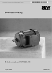
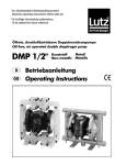
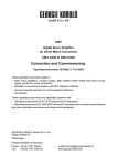
Bedienungsanleitung
Instruction manual
Prescriptions de Service
Istruzioni per l'uso
Dauermagnetbremse MB für Motoren und Drehfeldmagnete
Permanent magnet brake MB for three-phase motors, torque motors
Frein MB à aimant permanent pour des moteurs
et des électro-aimants à champ tournant
Freno magnetico permanente MB per motori e magneti a campo rotante
Art.-Nr. 221008-01
Ver. 03.03
GEORGII KOBOLD GmbH & Co. KG
Ihlinger Strasse 57
72160 Horb
Bundesrepublik Deutschland
Tel. +49 (0) 7451 5394-0
Fax +49 (0) 7451 5394-53
e-Mail [email protected]
www.georgii-kobold.de
Bedienungsanleitung
221008 03/03
Dauermagnetbremse MB für Motoren und Drehfeldmagnete
Allgemeines
Die Dauermagnet-Einscheibenbremsen MB sind für den direkten Anbau an GEORGII KOBOLD Motoren und
Drehfeldmagnete konstruiert. Abmessungen, Formgebung, Luftführung, Wärmekoppelung, automatischer
Verschleißausgleich und die erreichten technischen Daten machen die Antriebseinheit zu einem hochwertigen
Produkt.
Durch die Wirkung des Dauermagneten hat die Bremse im spannungslosen Zustand ihr volles Bremsmoment.
Das Anlegen von Gleichspannung bewirkt in der Bremslüftspule ein dem Dauermagnetfeld entgegengerichtetes
Elektromagnetfeld und kompensiert dieses. Eine im Teil 11 eingebaute Tellerfeder stützt sich an einem
Schleppring ab und sorgt für eine vollkommene Aufhebung des Reibungsschlusses.
Anschlussspannung
Steht Wechselspannung zur Verfügung, erhält der Motor im Klemmenkasten einen Brückengleichrichter mit
Überspannungsschutz, Teile-Nr. 044070.... Der angelegten sinusförmigen Wechselspannung entspricht eine
ca. 0,9-fache Gleichspannung. Beispiel : 230V Wechselspannung ergeben ca. 200V Gleichspannung am
Gleichrichterausgang. Der Gleichspannungswert ist an der Bremse aufgestempelt, während das
Motorleistungsschild die Wechselspannungsangabe enthält.
Steht Gleichspannung zur Verfügung, erhält der Motor im Klemmenkasten lediglich einen Überspannungsschutz
je nach den Platzverhältnissen in Form einer Anschlussgarnitur 0440872.. oder eines Bauteiles 021043...
Die Stempelung des Leistungsschildes entspricht der Gleichspannungsangabe auf der Bremse.
Spannungstoleranz
Die Bremse ist funktionsfähig, wenn die angelegte Gleichspannung innerhalb des 0,85- bis 1,1-fachen der
Nenngleichspannung liegt.
Schutzart
Bremse MB
Bremse MB../S5
Bremse MBZ
lP 40
IP 40 mit nichtrostenden Ankersegmenten
IP 55
Verunreinigungen an den Bremsflächen, besonders durch Fette und Öle, reduzieren das Bremsmoment. Bei
Verwendung im Freien empfiehlt sich ein Schutzdach.
Anbaulage
Die Bremse kann in allen Lagen betrieben werden. Sehr starke Vibration und senkrechte Lage des Motors mit
Abtrieb nach oben (Bauformen IM V6, IM V9 oder IM V19) können Sondermaßnahmen notwendig machen.
Bitte nehmen Sie in solchen Fällen unsere Beratung in Anspruch.
Anschluss
Im Klemmenkasten des Motors oder Drehfeldmagneten befindet sich ein Schaltbild.
Wartung
Die Bremse verlangt während ihrer langen Lebensdauer keine Nachstellung. Durch die Konstruktion bedingt
(luftspaltenloses Magnetsystem) reiben auch die metallischen Polflächen aufeinander und verschleißen
zusammen mit dem Reibbelag. Der Verschleiß wird automatisch ausgeglichen, dadurch bleiben Lüftung und
Nachlauf konstant. Der Verschleißzustand kann nach dem Abnehmen der Lüfterhaube 7 gemessen werden.
Das Maß A im neuen Zustand und bei abgenütztem Bremsbelag ist in der nachfolgenden Tabelle festgehalten.
Wenn aus irgendwelchen Gründen der unter »Allgemein« erwähnte Schleppring so stark auf der Welle sitzt, dass
sich das Bremsmoment auffallend verringert, empfiehlt sich folgendes Vorgehen :
Lüfterhaube 7 und Anschlagscheibe 5 entfernen, umlaufendes Bremsenteil 4 mittels Abziehvorrichtung abziehen
bzw. durch Anlegen von Spannung die Bremse lüften und das umlaufende Bremsenteil abnehmen. Verzahnung
und Welle mit Optimoly PL bestreichen und die Montage der Teile 4, 5 und 7 wieder vornehmen.
Das gesamte Lüfterteil mit Nachführelement ist ein begrenzt lagerfähiges Produkt. Bei längerem Stillstand oder
Einlagerung des Motors ist bei nicht nachstellendem Lüfterteil analog zu verfahren.
Type
K2407
KOD 3.. MB
KOD 4.. MB
KOD 5 MB
KOD 6.. MB
KOD 7.. MB
KOD 8.. MB
KOD 5.. MB 54
KOD 6.. MB 65
KOD 7.. MB 76
PO 5.. MB
PO 6.. MB
PO 7.. MB
Maß A
neu
abgenützt
9,1
9,1
9
10,7
12,9
12,9
9,1
9
10,7
9,1
9
10,7
6
6
6
7
8
8
6
6
7
6
6
7
1
K2406
Austausch der
MB-Bremse
a) Lüfterhaube 7 abnehmen.
b) Anschlagscheibe 5 abschrauben.
c) Anschlüsse der Bremslüftspule im Klemmenkasten am Gleichrichter abklemmen. Auf Polarität (Farbe der
Anschlüsse) achten !
d) Mittels Abziehvorrichtung, deren Klauen hinter dem am Lüfter befestigten Nachführelement 11 angesetzt
werden, das umlaufende Bremsenteil 4 abziehen bzw. durch Anlegen von Spannung die Bremse lüften und
das umlaufende Bremsenteil abnehmen.
e) Befestigungsschrauben 8 lösen und das feststehende Bremsenteil abnehmen.
Soll der Motor weiter demontiert werden :
f) 4 Gewindebolzen bzw. Schrauben 1 (ggf. vorher Zwischenring 10) entfernen.
g) Läufer 6 mit Lagerschild 2 herausnehmen.
h) Nach dem Lösen des Kugellagerdeckels 9 kann das Lagerschild abgenommen werden.
i) Bei der Montage in umgekehrter Reihenfolge vorgehen. Verzahnung und Wellenende - in den Schnittzeichnungen durch strichpunktierte Linien gekennzeichnet - mit Optimoly PL bestreichen !
Bitte beachten!
In der Kerbverzahnung der Lüfterbohrung ist ein doppeltbreiter Zahn.
Der Lüfter kann daher nur in einer Stellung auf die Welle aufgeschoben werden.
Gewaltanwendung vermeiden !
Bis das volle Bremsmoment wirksam wird, können ca. 50 -100 Schaltzyklen des Bremsmotors notwendig sein.
Abgenutzte Bremsen sind komplett auszutauschen. Beim Ersatz einer MA- durch eine MB-Bremse ist u. a. der Austausch des
Lagerschildes erforderlich.
Bitte bestellen Sie gegebenenfalls den gesamten Umbausatz.
2
Instruction manual
221008E 03/03
Permanent magnet brake MB for three-phase motors, torque motors
General
The permanent magnet single disc brakes MB are designed for direct mounting to GEORGII KOBOLD motors.
Dimensions, shaping, cooling and heat dissipation, automatic abrasion compensation and the achieved technical
data make the drive unit a superior product.
For effect of the permanent magnet at the state of dead, the brake has its full braking couple. Switching on d.c. to
the brake lifting coil causes a field vs. the field of the permanent magnet and is compensating it. A cup spring
mounted in part 11, supported by a drag ring fully eliminates the friction contact.
Connection
voltage
If a.c. voltage is available the terminal box of the motor is equipped with a bridge rectifier with overvoltage
protection, part no. 044070... An approx. 0,9-times d.c. voltage corresponds to the applied sinusoidal a.c. voltage.
Example: 230 V a.c, voltage results in approx. 200 V d.c. voltage at the rectifier output. The d.c. voltage value is
stamped on the brake, while the motor type plate shows the a.c. voltage value.
If d.c. voltage is available the terminal box of the motor is only equipped with an overvoltage protection according
to the space available either in the form of a connection kit 044087Z.. or a component 021043.. The stamping of
the type plate corresponds to the indication of the d.c. voltage shown on the brake.
Voltage
tolerance
The brake operates when the applied d.c. voltage is within the range of the 0,85 to 1,1-times rated d.c. voltage.
Protection
Brake MB
Brake MB 55
Brake MBZ
IP 40
IP 40 with rust resisting armature Segments
IP 55
Dirty oiled-up brake faces reduce the brake torque. If the motor operates in exposed positions, a protective cover
should be fitted, but without impairing the flow of cooling air to the motor.
Mounting
position
The brake can be operated in all mounting positions. Very strong vibration and vertical position of the motor with
shaft end upwards (mounting types IM V6, IM V9 or IM V19) may require special arrangements. Please consult
us in such cases.
Connection
See wiring diagram in the terminal box of the motor.
Maintenance
According to its long duration of life the brake does not need any readjustment. Since it is a gapless magnet
system, the metallic pole faces rub one against the other and thus wear together with the brake lining. The wear
is automatically compensated thus ensuring that the brake fully maintains its efficiency. The brake wear can be
measured after removal of fan hood 7. Dimension "A" in new and worn out condition of the brake lining is shown
in the table below.
If for any reasons the drag ring mentioned under "general" adheres so much to the shaft that the brake torque
decreases remarkably, proceed as follows: Remove fan hood 7 and stop disc 5 as well as the rotating part of the
brake 4 by using a pulley extracting tool, resp. lift the brake by applying voltage and remove the rotating part of
the brake, apply "0ptimoly PL" grease to the splined shaft end and mount parts 4, 5 and 7 again.
The entire fan section with follow-up element is a product that can be stocked for a limited period only. Proceed
analogously for a non-regulating fan section in the case of longer standstill or storage of the motor.
Type
KOD 3.. MB
KOD 4.. MB
KOD 5 MB
KOD 6.. MB
KOD 7.. MB
KOD 8.. MB
KOD 5.. MB 54
KOD 6.. MB 65
KOD 7.. MB 76
PO 5.. MB
PO 6.. MB
PO 7.. MB
Dimension "A"
new
worn out
9,1
9,1
9
10,7
12,9
12,9
9,1
9
10,7
9,1
9
10,7
6
6
6
7
8
8
6
6
7
6
6
7
K2407
3
K2406
Replacement of the
MB-brake
a) Remove fan hood 7
b) Unscrew stop disc 5
c) Disconnect brake lift coil terminals in the terminal box from the rectifier. Watch polarity (lead colours)!
d) Remove the rotating Part of the brake 4 by using a pulley extracting tool, the claws of which should be applied
behind the adjusting device 11 fixed to the fan, resp. lift the brake by applying voltage and remove the rotating
part of the brake.
e) Unscrew fixing screws 8 and remove stationary part of the brake.
If the motor is required to be dismantled further, proceed as follows:
f) Remove 4 threaded bolts, resp. screws 1 (at first possibly intermediate ring 10).
g) Remove rotor 6 with endshield 2.
h) Remove endshield after removal of bearing retaining plate 9.
i) Assemble in reverse order, apply before "Optimoly PL" grease to the splined shaft end as shown in the above
sectional drawing!
Please note!
There is only one position for pushing the fan back on the shaft as the double tooth has to be carefully engaged into
the double space on the serrated shaft. - Avoid to employ any force! Approx. 50 to 100 switching cycles of the brake motor are necessary until the full brake torque becomes efficient.
Worn brakes should be replaced by a complete new assembly. When a MA-brake is replaced by a MB-brake the endshield has to be
exchanged too!
Please possibly order the whole conversion kit.
4
Prescriptions de Service
221008F 03/03
Frein MB à aimant permanent pour des moteurs
et des électro-aimants à champ tournant
Généralités
Tension de
raccordement
Tolérance de
tension
Protection
Position de
montage
Raccordement
Entretien
Les freins monodisques MB actionnés par aimant permanent ont été conçus pour montage directe à des moteurs
et des électro-aimants à champ tournant GEORGII KOBOLD. Dimensions, façonnage, ventilation et dissipation
de chaleur, compensation automatique de l'usure et les données techniques rendent l'unité d'entraînement un
produit supérieur.
Par attraction de l'aimant permanent, le frein est toujours serré quand le moteur est déclenché. Pour libérer le
frein, il suffit d'appliquer la tension fournie par un redresseur sur la bobine dans la partie fixe du frein. Cette
dernière produit ou champ magnétique opposé à celui de l'aimant permanent, se trouvant aussi dans la partie
fixe du frein derrière la bobine, et le neutralise. Un ressort de dégagement qui s'appuie sur une bague adhérente
située sur l'arbre du moteur repousse la partie rotative du frein, joint avec l'arbre par une cannelure, de telle sorte,
que tout frottement soit éliminé et permet ainsi du moteur de démarrer librement. Il est admissible de déserrer le
frein en permanence, lorsque le moteur est arrêté.
Si tension alternative est disponible, la boîte à bornes du moteur est équipée d'un redresseur en pont, pièce no.
044070.... avec protection contre les surtensions. Une tension continue d'environ 0,9 fois autant correspond à la
tension alternative sinusoidale appliquée. Exemple: 230 V tension alternative résultent en env. 200 V tension
continue à la sortie du redresseur. La valeur de la tension continue est marquée sur le frein, tandis que la plaque
signalétique du moteur montre la tension alternative.
Si tension continue est disponible, la boîte à bornes du moteur est seulement équipée d'une protection contre les
surtensions selon l'espace disponible sous forme d'une garniture de raccordement 044087Z.. ou d'une pièce
021043... La plaque signalétique du moteur montre la tension continue indiquée sur le frein.
Le frein fonctionne, si la tension continue appliquée est dans la gamme de 0,85 à 1,1 fois autant la tension
continue nominale.
frein MB
IP40
frein MB..S5
IP40 avec des segments d'induit inoxydables
frein MBZ
IP55
Des pollutions, spécialement de graisse ou d'huile, sur les garnitures du frein réduisent le couple de freinage.
Lors de montage en plein-air, prévoir ou toît de protection.
Le frein est indifférent à son position de montage. Très forte vibration et position verticale du moteur avec bout
d'arbre vers le haut (formes de fixation IM V6, IM V9) peuvent rendre nécessaire des mesures spéciales. Veuillez
nous consulter dans de tels cas.
Voir schémas de connexion dans la boîte à bornes du moteur ou de l'électro-aimant à champ tournant.
Le frein ne nécessite aucun réglage pendant sa très longue durée de vie. Sa construction spéciale (sans
entrefer) nécessite un frottement et une usure des anneaux de pôles créant ainsi des rainures dans les
garnitures du frein. L'usure est compensée automatiquement, de sorte que les caractéristiques de freinage
restent constantes pendant toute sa durée de vie. Après avoir enlevé le capot de ventilateur 7, l'état d'usure peut
être mesuré. La dimension A en état neuf et avec garniture de frein usé est indiquée dans la tabelle ci-dessous.
Si, pour des raisons quelconques, la bague adhérente décrite sous "Généralités" adhère à l'arbre tellement que
le couple de freinage diminue d'une manière frappante, procéder comme suit: Enlever le capot de ventilateur 7 et
la rondelle butée 5, retirer la partie rotative du frein 4 au moyen d'un extracteur, resp. libérer le frein par
application de tension et retirer la partie rotative du frein. Graisser la cannelure et l'arbre à 0ptimoly PL et
remonter les pièces 4, 5 et 7.
L’unité de ventilateur complète avec élément d’asservissement est un produit entreposable pour une durée
limitée. En cas d’immobilisation prolongée ou d’emmagasinage du moteur, procéder de façon analogue pour
l’unité de ventilateur non compensatrice.
Type
K2407
KOD 3.. MB
KOD 4.. MB
KOD 5 MB
KOD 6.. MB
KOD 7.. MB
KOD 8.. MB
KOD 5.. MB 54
KOD 6.. MB 65
KOD 7.. MB 76
PO 5.. MB
PO 6.. MB
PO 7.. MB
Dimension A
neuf
usé
9,1
9,1
9
10,7
12,9
12,9
9,1
9
10,7
9,1
9
10,7
6
6
6
7
8
8
6
6
7
6
6
7
5
K2406
Remplacement
du frein MB
a) Enlever le capot de ventilateur 7.
b) Dévisser la rondelle butée 5.
c) Déconnecter la bobine de frein dans la boîte à bornes du redresseur. Faire attention à la polarité (couleur des
raccordements)!
d) Retirer la partie rotative du frein 4 au moyen d'un extracteur dont les griffes sont à placer derrière l'élément
d'ajustage 11, vissé au ventilateur, ou libérer le frein par application de tension et retirer la partie rotative du frein.
e) Dévisser les vis de fixation 8 et enlever la partie fixe du frein.
f) Enlever les 4 tiges filetées 1 (le cas échéant enlever l'anneau intermédiaire 10 au préalable).
g) Retirer le rotor 6 avec la flasque-palier 2.
h) Après avoir libéré le couvercle de roulement á billes 9, le flasque-palier peut être enlevé.
i) Lors du montage procéder en ordre inverse. Graisser la cannelure et le bout d'arbre - marqués dans les vues en
coupe par des traits mixtes - à Optimoly PL.
Attention!
Dans la cannelure du forage de ventilateur se trouve une dent a largeur double de telle sorte que le ventilateur ne
peut être glissé sur l'arbre que dans une seule position. Eviter l'emploi de la force!
Env. 50 à 100 cycles d'opération sont nécessaires jusqu'à le couple de freinage plein devient efficace.
Des freins usés doivent être remplacés complètement. Si un frein du type MA est remplacé par un frein du type MB, le flasque-palier doit
être reimlacé entre autres.
Le cas échéant commander le jeu de modification complet s.v.p.
6
Istruzioni per l'uso
221008I 03/03
Freno magnetico permanente MB per motori e magneti a campo rotante
In generale
I freni monodisco a magnete permanente MB sono costruiti per il montaggio diretto su motori e magneti a campo
rotante GEORGII KOBOLD. Dimensioni, foggiatura, conduzione d'aria, accoppiamento termico, compensazione
automatica dell'usura e i dati tecnici raggiunti fanno di questo gruppo azionatore un prodotto di elevato pregio.
In assenza di tensione il freno possiede la sua piena coppia di frenatura mediante l'azione del magnete
permanente. Applicando tensione continua si provoca nell'avvolgimento d'allentamento del freno un controcampo
elettromagnetico nei confronti del campo magnetico permanente, compensandolo. Un molla a tazza incorporata
nel pezzo 11 va ad appoggiarsi su un anello di trascinamento, provocando un completo annullamento del blocco
da attrito.
Tensione di
allacciamento
Se vi è a disposizione una tensione alternata, al motore si applicherà nella scatola dei morsetti un raddrizzatore a
ponte con protezione di sovratensione, Nr. del pezzo 044070....La tensione alternata sinusoidale applicata
corrisponde a 0,9 volte la tensione continua risultante. Esempio : 230V di tensione alternata forniscono ca. 200V
di tensione continua. Il valore di tensione continua è timbrato sul freno, mentre la targhetta di potenza del motore
riporta il valore della tensione alternata.
Se vi è a disposizione tensione continua , il motore verrà corredato nella scatola dei morsetti solamente di una
protezione contro le sovratensioni, a seconda dello spazio a disposizione, sotto forma della componente da
attaccarsi 0440872.. oppure del pezzo d'accessorio 021043... La timbratura sulla targhetta di potenza
corrisponde all'indicazione di tensione continua sul freno.
Tolleranza di
tensione
Il freno è funzionante quando la tensione continua applicata si venga a trovare tra le 0,85 e le 1,1 volte la
tensione continua nominale.
Tipo di protezione
freno MB
freno MB../S5
freno MBZ
lP 40
IP 40 con segmenti d'indotto inossidabili
IP 55
Imbrattamenti sulle superfici frenanti, in particolare da grasso e da olio, riducono la coppia di frenatura.
Nell'impiego all'aperto si consiglia una tettoia di protezione.
Posizione di
montaggio
Il freno può venir fatto funzionare in tutte le posizioni. Un'elevata vibrazione e la posizione verticale del motore
con la presa di forza in alto (modelli IM V6, IM V9 e IM V19) possono rendere necessarie misure speciali. In
casi del genere si prega di usufruire della ns. consulenza.
Attacco
Nella scatola dei morsetti del motore o dei magneti a campo rotante si trova uno schema dei circuiti.
Manutenzione
Il freno non richiede post-registrazioni nel corso della sua lunga durata di vita. In dipendenza dalla sua
costruzione (sistema magnetico senza intraferro) sfregano tra loro anche le superfici metalliche dei poli,
consumandosi assieme con lo strato di attrito. Il logorio viene compensato automaticamente, con ciò rimangono
costanti sia allentamento che incidenza. Lo stato di usura può venir misurato, togliendo la calotta del ventilatore
7. La misura A a freno nuovo e a ferodo del freno consumato viene fissata nella seguente tabella.
Quando, per una qualsiasi ragione, l'anello di trascinamento menzionato al punto "In generale" vada ad
appoggiarsi sull'albero in maniera così forte, che la coppia di frenatura si riduca in modo molto evidente, si
consiglia il seguente procedimento:
togliere la vite del ventilatore 7 e il disco di battuta 5, mediante un dispositivo di estrazione cavare la parte
rotante del freno 4 oppure, applicando la tensione, allentare il freno, togliendone la parte rotante dello stesso.
Spalmare con Optimoly PL sia la dentatura che l'albero, rimontando, indi, i pezzi 4, 5 e 7.
L'intera unità di ventilazione con elemento di allineamento può restare inutilizzata soltanto per un periodo di
tempo limitato. In caso di soste più lunghe o immagazzinaggio del motore, procedere come in precedenza se
l'unità di ventilazione non si registra.
Tipo
Misura “A”
nuovo
K2407
KOD 3.. MB
KOD 4.. MB
KOD 5 MB
KOD 6.. MB
KOD 7.. MB
KOD 8.. MB
KOD 5.. MB 54
KOD 6.. MB 65
KOD 7.. MB 76
PO 5.. MB
PO 6.. MB
PO 7.. MB
9,1
9,1
9
10,7
12,9
12,9
9,1
9
10,7
9,1
9
10,7
consumato
6
6
6
7
8
8
6
6
7
6
6
7
7
K2406
Sostituzione del
freno MB
a) Togliere la calotta del ventilatore 7.
b) Svitare il disco di battuta 5.
c) Staccare gli attacchi dell'avvolgimento di allentamento del freno sul raddrizzatore nella scatola die
morsetti. Fare attenzione alla polarità (colore degli attacchi) !
d) Mediante l'estrattore, i denti del quale vanno innestati sull'elemento di guida 11 fissato dietro il
ventilatore, togliere la parte rotante del freno 4 e, applicando la corrente, allentare il freno per estrarne
la parte rotante dello stesso.
e) Allentare le viti di fissaggio 8 , togliendo, indi, la parte fissa del freno.
Se si deve smontare il motore:
f) Togliere i 4 bulloni o le viti 1 (nei dovuti casi va tolto prima l'anello intermedio 10).
g) Togliere il rotore 6 con lo scudo del cuscinetto 2.
h) Dopo aver allentato il cappello del cuscinetto a sfere 9, può venir tolto lo scudo dello stesso.
i) Nel montaggio procedere nella sequenza inversa. Spalmare con Optimoly PL sia la dentatura che
l'estremità dell'albero - contrassegnate nel disegno in sezione mediante una linea tratteggiata - !
Si prega di osservare!
Nel profilo a denti triangolari del foro del ventilatore vi è un dente doppio.
Pertanto il ventilatore potrà venire inserito sull'albero solo in una determinata posizione.
Evitare un innesto forzato !
Fino alla completa attività della coppia di frenatura, sono necessari ca. 50 - 100 cicli del motore con
freno.
Freni consumati vanno sostituiti completi. Nella sostituzione di un freno MA con un freno MB è necesseria anche la sostituzione dello
scudo del cuscinetto.
Nei dovuti casi si prega di ordinare l'intera serie del ricambio.
8