1
1 (46)
Page
CMO Operations & Logistics
Training and Vendor Development
Multimedia Creation & Support
Approved 10.0
MGR
15.Oct.2007
CONFIDENTIAL
SERVICE MANUAL
Level 1&2
RM-260
RM-198
RM-188
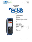
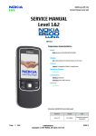
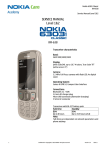
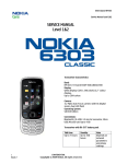
Transceiver characteristics:
Band: Quad-band GSM/EDGE phone 850/900/1800/1900MHz
Camera: VGA camera with 4x digital post zoom
Display:
- Main display: 128 x 160-pixel, 1.8” CSTN passive LCD with
262,144 colors
- C over display: 96 x 68-pixel, FSTN, black/ white with blue LEDs
Bluetooth
FM stereo radio
Connector: Pop-Port™ Connector
Memory: microSD™
Transceiver with BL-5C Li-Ion battery pack
Talk time
Standby
Note
up to 5h
up to 10days
Depends on network
parameters
Environmental characteristics:
•
Service Manual 6085 RM-198 / 6086 RM-188/RM-260
Lead-free soldered
Copyright © 2006-2007 NOKIA Corporation. All rights reserved.
Page
CMO Operations & Logistics
Training and Vendor Development
Multimedia Creation & Support
2 (46)
Approved 10.0
MGR
15.Oct.2007
CONFIDENTIAL
TABLE OF CONTENTS
1.
2.
3.
4.
5.
6.
7.
8.
9.
10.
11.
12.
13.
14.
15.
16.
17.
18.
19.
20.
21.
22.
23.
24.
25.
26.
Page
INTRODUCTION
EXPLODED VIEW
SPARE PARTS OVERVIEW
LEVEL 2 SOLDER COMPONENTS
SERVICE DEVICES
SW-UPDATE
UPPER BLOCK DISASSEMBLY
UPPER BLOCK ASSEMBLY
LOWER BLOCK DISASSEMBLY
LOWER BLOCK ASSEMBLY
LEGEND FOR QUICK TROUBLE SHOOTER
QUICK TROUBLE SHOOTER - POWER ON
QUICK TROUBLE SHOOTER - CHARGING
QUICK TROUBLE SHOOTER - NO SERVICE
QUICK TROUBLE SHOOTER - SIM
QUICK TROUBLE SHOOTER - EARPIECE
QUICK TROUBLE SHOOTER - IHF SPEAKER QUICK TROUBLE SHOOTER - DISPLAY SMALL QUICK TROUBLE SHOOTER - DISPLAY QUICK TROUBLE SHOOTER - MICROPHONE QUICK TROUBLE SHOOTER - KEYMAT QUICK TROUBLE SHOOTER - VIBRA QUICK TROUBLE SHOOTER - VOLUME KEYS QUICK TROUBLE SHOOTER - CAMERA KEY
QUICK TROUBLE SHOOTER - MEMORY CARD READER QUICK TROUBLE SHOOTER - CAMERA
3
4
5
6
7
9
10
15
23
27
31
32
33
34
35
36
37
38
39
40
41
42
43
44
45
46
CHANGE HISTORY
Status
Version No.
Date
Comments
Draft
0.1
09.OKT.2006
Initial draft
Approved
1.0
23.Okt.2006
Approval
Approved
2.0
24.Okt.2006
SS-6 added to the Tools chapter
Approved
3.0
25.Okt.2006
Spare Parts overview added
Approved
4.0
22.Nov.2006
6086 RM-188 added
Approved
5.0
21.Feb.2007
Exploded view & Spare Parts overview update; General Recycling
recommendation added
Approved
6.0
14.Mrz.2007
Exploded view & Spare Parts overview update, Page Battery Test and
GONOGO Test removed
Approved
7.0
20.Mrz.2007
RM-260 added
Approved
8.0
29.May.2007
Exploded view & Spare Parts overview update
Approved
9.0
28.Sept.2007
Exploded view & Spare Parts overview update
Approved
10.0
15.Oct.2007
Exploded view & Spare Parts overview update
Service Manual 6085 RM-198 / 6086 RM-188/RM-260
Copyright © 2006-2007 NOKIA Corporation. All rights reserved.
Page
CMO Operations & Logistics
Training and Vendor Development
Multimedia Creation & Support
3 (46)
Approved 10.0
MGR
CONFIDENTIAL
15.Oct.2007
1. INTRODUCTION
The purpose of this document is to help NOKIA service levels 1 and 2 workshop technicians to carry out service to
NOKIA products. This Service Manual is to be used only by authorized NOKIA service suppliers, and the content of it is
confidential. Please note that NOKIA provides also other guidance documents (e.g. Service Bulletins) for service suppliers, follow these regularly and comply with the given instructions.
While every endeavor has been made to ensure the accuracy of this document, some errors may exist.
If you find any errors or if you have further suggestions, please notify NOKIA using the address below:
mailto:[email protected]
Please keep in mind also that this documentation is continuously being updated and modified, so watch always out
for the newest version.
Warnings and Cautions
Please refer to the phone’s user guide for instructions relating to operation, care and maintenance including important safety information. Note also the following:
Warnings:
1. CARE MUST BE TAKEN ON INSTALLATION IN VEHICLES FITTED WITH ELECTRONIC ENGINE MANAGEMENT SYSTEMS
AND ANTI–SKID BRAKING SYSTEMS. UNDER CERTAIN FAULT CONDITIONS, EMITTED RF ENERGY CAN AFFECT THEIR
OPERATION. IF NECESSARY, CONSULT THE VEHICLE DEALER/MANUFACTURER TO DETERMINE THE IMMUNITY OF VEHICLE ELECTRONIC SYSTEMS TO RF ENERGY.
2. THE HANDPORTABLE TELEPHONE MUST NOT BE OPERATED IN AREAS LIKELY TO CONTAIN POTENTIALLY EXPLOSIVE
ATMOSPHERES, EG PETROL STATIONS (SERVICE STATIONS), BLASTING AREAS ETC.
3. OPERATION OF ANY RADIO TRANSMITTING EQUIPMENT, INCLUDING CELLULAR TELEPHONES, MAY INTERFERE WITH
THE FUNCTIONALITY OF INADEQUATELY PROTECTED MEDICAL DEVICES. CONSULT A PHYSICIAN OR THE MANUFACTURER OF THE MEDICAL DEVICE IF YOU HAVE ANY QUESTIONS. OTHER ELECTRONIC EQUIPMENT MAY ALSO BE SUBJECT TO
INTERFERENCE.
Cautions:
1. Servicing and alignment must be undertaken by qualified personnel only.
2. Ensure all work is carried out at an anti–static workstation and that an anti–static wrist strap is worn.
3. Use only approved components as specified in the parts list.
4. Ensure all components, modules screws and insulators are correctly re–fitted after servicing and alignment.
5. Ensure all cables and wires are repositioned correctly.
Electrostatic discharge can easily damage the sensitive components of electronic products.
Therefore every Service Supplier has to take care of all precautions, which are mentioned in the
service level related “Service Partner Requirements”, available on NOKIA Online. Also see ESD
Protection Requirements in this Service Manual.
Service Manual 6085 RM-198 / 6086 RM-188/RM-260
Copyright © 2006-2007 NOKIA Corporation. All rights reserved.
Page
CMO Operations & Logistics
Training and Vendor Development
Multimedia Creation & Support
4 (46)
Approved 10.0
MGR
CONFIDENTIAL
15.Oct.2007
2. EXPLODED VIEW
See corresponding ITEM/CIRCUIT REF in the Spare Parts Service Bulletins on NOL.
Service Manual 6085 RM-198 / 6086 RM-188/RM-260
Copyright © 2006-2007 NOKIA Corporation. All rights reserved.
Page
CMO Operations & Logistics
Training and Vendor Development
Multimedia Creation & Support
5 (46)
Approved 10.0
MGR
CONFIDENTIAL
15.Oct.2007
3. SPARE PARTS OVERVIEW
Service Manual 6085 RM-198 / 6086 RM-188/RM-260
Copyright © 2006-2007 NOKIA Corporation. All rights reserved.
Page
CMO Operations & Logistics
Training and Vendor Development
Multimedia Creation & Support
6 (46)
Approved 10.0
MGR
CONFIDENTIAL
15.Oct.2007
4. LEVEL 2 SOLDER COMPONENTS
Service Manual 6085 RM-198 / 6086 RM-188/RM-260
Copyright © 2006-2007 NOKIA Corporation. All rights reserved.
Page
CMO Operations & Logistics
Training and Vendor Development
Multimedia Creation & Support
7 (46)
Approved 10.0
MGR
CONFIDENTIAL
15.Oct.2007
5. SERVICE DEVICES
FLS-4S incl. ACF-8, Driver and User Guide
Dongle and flash device incorporated into one package, developed specifically for POS use.
ACF-8
Universal Power Supply is used to power FLS-4S.
Travel Charger AC-4
Small and lightweight charger for fast charging of your phone
battery.
Internal Battery BL-5C
Inserted under the back cover, this Li-Ion battery provides
power in a lightweight package.
SS-104
Domesheet & Display alignment jig
SS-88
Camera removal tool.
CA-53
Service Cable to connect the PC with the Pop-Port™ connector.
Service Manual 6085 RM-198 / 6086 RM-188/RM-260
Copyright © 2006-2007 NOKIA Corporation. All rights reserved.
Page
CMO Operations & Logistics
Training and Vendor Development
Multimedia Creation & Support
8 (46)
Approved 10.0
MGR
15.Oct.2007
CONFIDENTIAL
SS-6
Hinge opening tool.
RJ-154
Soldering Jig
Lead-free Solder Wire
Mandatory for lead-free products (Level 2 only).
0772040
NMP Standard Toolkit (V2)
For more informations refer to the Service Bulletin (SB-011) on
NOKIA Online.
Supplier or manufacturer contacts for tool re-order can be
found in “Recommended service equipment” document on
NOKIA Online.
Service Manual 6085 RM-198 / 6086 RM-188/RM-260
Copyright © 2006-2007 NOKIA Corporation. All rights reserved.
Page
CMO Operations & Logistics
Training and Vendor Development
Multimedia Creation & Support
9 (46)
Approved 10.0
MGR
CONFIDENTIAL
15.Oct.2007
6. SW-UPDATE
Flash Concept – (Point of Sales)
To use FLS-4S Flash Dongle you have to follow the user guide inside the sales package. Please check always for the
latest version of flash software, which is available on
NOKIA Online.
Service Manual 6085 RM-198 / 6086 RM-188/RM-260
Copyright © 2006-2007 NOKIA Corporation. All rights reserved.
Page 10 (46)
CMO Operations & Logistics
Training and Vendor Development
Multimedia Creation & Support
Approved 10.0
MGR
CONFIDENTIAL
15.Oct.2007
7. UPPER BLOCK DISASSEMBLY
1. Needed tools: SS-88 camera removal tool, the SS-6, the SS93, metal tweezers, a bit holder with a Torx Plus size 6 bit, a
torque driver...
2. ... and the SS-104 for fitting the adhesives and displays.
3. Always cover the windows with a protective film.
4. Remove the battery if it is still inserted.
5. Use the SS-93 to pry open the B-COVER UPPER ASSEMBLY,
starting at the top.
6. Release the clips shown, on both sides.
Service Manual 6085 RM-198 / 6086 RM-188/RM-260
Copyright © 2006-2007 NOKIA Corporation. All rights reserved.
Page 11 (46)
CMO Operations & Logistics
Training and Vendor Development
Multimedia Creation & Support
Approved 10.0
MGR
CONFIDENTIAL
7. Shift the B-Cover Assy to the hinge direction and lift it up.
8. Cover the LCD PM with a protective film.
9. Carefully release and remove the CAMERA MODULE with the
SS-88 Camera removal tool.
10. Disconnect the flex connector.
15.Oct.2007
11. Carefully release the adhesive of the LCD PM with the SS-93. 12. Remove the LCD PM.
Service Manual 6085 RM-198 / 6086 RM-188/RM-260
Copyright © 2006-2007 NOKIA Corporation. All rights reserved.
Page 12 (46)
CMO Operations & Logistics
Training and Vendor Development
Multimedia Creation & Support
Approved 10.0
MGR
CONFIDENTIAL
15.Oct.2007
13. Disconnect the flex connector.
14. Fit the Torx Plus size 6 bit.
15. Unscrew the four screws and remove them.
16. Lift out the PWB 1WJ.
17. Cover the innerside window with a plastic film.
18. Carefully lift out the EARPIECE. Note that the Speaker Gasket
will be destroyed during the removal, and must be replaced
when reassemble.
Service Manual 6085 RM-198 / 6086 RM-188/RM-260
Copyright © 2006-2007 NOKIA Corporation. All rights reserved.
Page 13 (46)
CMO Operations & Logistics
Training and Vendor Development
Multimedia Creation & Support
MGR
CONFIDENTIAL
19. Cover the display with a plastic film.
20. Release the flex connector.
21. Release the LCD BACK ADHESIVE with the SS-93.
22. Carefully remove the LCD CSDN.
23. Push out the glued in LCD WINDOW.
24. Unlock the clips of the ANTENNA CAP.
Service Manual 6085 RM-198 / 6086 RM-188/RM-260
Approved 10.0
15.Oct.2007
Copyright © 2006-2007 NOKIA Corporation. All rights reserved.
Page 14 (46)
CMO Operations & Logistics
Training and Vendor Development
Multimedia Creation & Support
Approved 10.0
MGR
CONFIDENTIAL
15.Oct.2007
25. Remove the cap as shown.
26. Bend down the hinge module with the SS-6 first. Note that
the SS-6 is very delicate and can be break easily.
27. Now lock the HINGE with a torx bit size 6 or similar.
28. Now, the A-COVER UPPER ASSEMBLY can be removed easily.
Mind the flex foil. The Hinge can be pulled out after the spring
expanding carefully if needed.
29. The disassembly procedure is now completed.
Service Manual 6085 RM-198 / 6086 RM-188/RM-260
Copyright © 2006-2007 NOKIA Corporation. All rights reserved.
Page 15 (46)
CMO Operations & Logistics
Training and Vendor Development
Multimedia Creation & Support
Approved 10.0
MGR
CONFIDENTIAL
15.Oct.2007
8. UPPER BLOCK ASSEMBLY
1. Assembly
2. Place the A-COVER UPPER ASSEMBLY. After locking the HINGE is shown.
3. Mind the flex foil.
4. Now expand the HINGE MODULE by removing the tool.
5. Ensure that the hinge expands completely before going on. 6. Place the ANTENNA CAP and click it into its place.
Service Manual 6085 RM-198 / 6086 RM-188/RM-260
Copyright © 2006-2007 NOKIA Corporation. All rights reserved.
Page 16 (46)
CMO Operations & Logistics
Training and Vendor Development
Multimedia Creation & Support
Approved 10.0
MGR
CONFIDENTIAL
15.Oct.2007
7. Use the SS-104 jig for positioning the displays and gasket
correctly.
8. Peel up the protective films from the displays.
9. Place the displays into their compartments as shown.
10. Fit new gaskets on the PWB 1WJ for both displays.
11. Now position the PWB to the guides of the jig.
12. Both guides must be fitted correctly.
Service Manual 6085 RM-198 / 6086 RM-188/RM-260
Copyright © 2006-2007 NOKIA Corporation. All rights reserved.
Page 17 (46)
CMO Operations & Logistics
Training and Vendor Development
Multimedia Creation & Support
MGR
CONFIDENTIAL
13. Place the PWB over the LCD PM first.
14. Mind the guides.
15. Push it down evenly.
16. Release the lever and remove the PWB.
17. Position the PWB to the LCD CSTN.
18. Again - mind the guides.
Service Manual 6085 RM-198 / 6086 RM-188/RM-260
Approved 10.0
15.Oct.2007
Copyright © 2006-2007 NOKIA Corporation. All rights reserved.
Page 18 (46)
CMO Operations & Logistics
Training and Vendor Development
Multimedia Creation & Support
Approved 10.0
MGR
CONFIDENTIAL
15.Oct.2007
19. Close the flex connector.
20. Cover the LCD with a protective film.
21. Smooth down the PWB evenly.
22. Cover the LCD CSTN with a protective film, too.
23. Close the flex connector.
24. Insert the EARPIECE into ist recess. Note that a new speaker
gasket must be fitted first.
Service Manual 6085 RM-198 / 6086 RM-188/RM-260
Copyright © 2006-2007 NOKIA Corporation. All rights reserved.
Page 19 (46)
CMO Operations & Logistics
Training and Vendor Development
Multimedia Creation & Support
MGR
CONFIDENTIAL
25. Push it down evenly.
26. Remove the protective film.
27. Place the PWB into the A-COVER ASSEMBLY.
28. Mind the guides.
29. Insert the screws.
30. Set the correct torque.
Service Manual 6085 RM-198 / 6086 RM-188/RM-260
Approved 10.0
15.Oct.2007
Copyright © 2006-2007 NOKIA Corporation. All rights reserved.
Page 20 (46)
CMO Operations & Logistics
Training and Vendor Development
Multimedia Creation & Support
MGR
CONFIDENTIAL
31. Tighten all screws.
32. Close this connector.
33. Insert the CAMERA MODULE with the SS-88.
34. Note the alignment tab.
35. Push it down evenly.
36. Remove the protective film.
Service Manual 6085 RM-198 / 6086 RM-188/RM-260
Approved 10.0
15.Oct.2007
Copyright © 2006-2007 NOKIA Corporation. All rights reserved.
Page 21 (46)
CMO Operations & Logistics
Training and Vendor Development
Multimedia Creation & Support
Approved 10.0
MGR
CONFIDENTIAL
15.Oct.2007
37. Fit a new SECONDARY GASKET to the B-COVER ASSEMBLY if
not already done.
38. Place the B-COVER at the shown side first and shift it into the
correct position.
39. Click all snaps into their places.
40. Note the correct positioning of the rear clips.
41. Open the unit, check the display and window for
cleanness.
42. Fit the new LCD WINDOW, beginning at the hinge side.
Service Manual 6085 RM-198 / 6086 RM-188/RM-260
Copyright © 2006-2007 NOKIA Corporation. All rights reserved.
Page 22 (46)
CMO Operations & Logistics
Training and Vendor Development
Multimedia Creation & Support
Approved 10.0
MGR
CONFIDENTIAL
15.Oct.2007
43. Smooth it down evenly.
Service Manual 6085 RM-198 / 6086 RM-188/RM-260
Copyright © 2006-2007 NOKIA Corporation. All rights reserved.
Page 23 (46)
CMO Operations & Logistics
Training and Vendor Development
Multimedia Creation & Support
Approved 10.0
MGR
CONFIDENTIAL
15.Oct.2007
9. LOWER BLOCK DISASSEMBLY
1. Needed tools: The SS-93, metall tweezers, a dental pick, a
bitholder, a Torx Plus size 6 bit and a torque driver.
2. Cover the windows with a protective film.
3. Unlock both latches of the ANTENNA CAP.
4. Open the assembly, release both upper clips of the ANTENNA
CAP.
5. Now, the cap can be removed easily.
6. Fit the Torx Plus size 6 bit.
Service Manual 6085 RM-198 / 6086 RM-188/RM-260
Copyright © 2006-2007 NOKIA Corporation. All rights reserved.
Page 24 (46)
CMO Operations & Logistics
Training and Vendor Development
Multimedia Creation & Support
MGR
CONFIDENTIAL
7. Unscrew the four screws.
8. Remove the screws.
9. Gently pry open the C-COVER with the SS-93.
10. Carefully lift up the cover.
11. Lift up the ENGINE MODULE, keep in mind that the flex foil
is still connected.
12. Open the connector with the SS-93.
Service Manual 6085 RM-198 / 6086 RM-188/RM-260
Approved 10.0
15.Oct.2007
Copyright © 2006-2007 NOKIA Corporation. All rights reserved.
Page 25 (46)
CMO Operations & Logistics
Training and Vendor Development
Multimedia Creation & Support
Approved 10.0
MGR
CONFIDENTIAL
15.Oct.2007
13. Push out the KEYMAT.
14. Remove the DC JACK with the DC PLUG.
15. Ease the MICROPHONE with the dental pick.
16. Carefully bend the C-COVER as shown to release the clips
holding the ANTENNA COVER.
17. Lever out the VIBRA MOTOR.
18. Release one clip of the SIM LID and remove it.
Service Manual 6085 RM-198 / 6086 RM-188/RM-260
Copyright © 2006-2007 NOKIA Corporation. All rights reserved.
Page 26 (46)
CMO Operations & Logistics
Training and Vendor Development
Multimedia Creation & Support
19. Lever out the IHF SPEAKER with the SS-93 first.
Approved 10.0
MGR
CONFIDENTIAL
15.Oct.2007
20. Remove it with tweezers now. Bear in mind that the IHF
GASKET will be destroyed during the removal and must be
renewed when reassembly.
21. The disassembly procedure is now finished.
Service Manual 6085 RM-198 / 6086 RM-188/RM-260
Copyright © 2006-2007 NOKIA Corporation. All rights reserved.
Page 27 (46)
CMO Operations & Logistics
Training and Vendor Development
Multimedia Creation & Support
Approved 10.0
MGR
CONFIDENTIAL
15.Oct.2007
10.LOWER BLOCK ASSEMBLY
1. Assembly
3. Insert the SIM LID and close it.
5. Click the ANTENNA MODULE into the C-COVER.
Service Manual 6085 RM-198 / 6086 RM-188/RM-260
2. Fit a new IHF GASKET and place the IHF SPEAKER into the
ANTENNA MODULE. Mind the correct positioning of the spring
contacts. Smooth it down evenly.
4. Place the VIBRA MOTOR. Do not bend the spring contacts.
6. Ensure ist correct positioning.
Copyright © 2006-2007 NOKIA Corporation. All rights reserved.
Page 28 (46)
CMO Operations & Logistics
Training and Vendor Development
Multimedia Creation & Support
MGR
CONFIDENTIAL
7. Insert the MICROPHONE.
8. And the DC JACK.
9. Place the KEYMAT.
10. Mind the correct positioning.
11. Bring the ENGINE MODULE into position near the hinge.
12. Close the flex connector.
Service Manual 6085 RM-198 / 6086 RM-188/RM-260
Approved 10.0
15.Oct.2007
Copyright © 2006-2007 NOKIA Corporation. All rights reserved.
Page 29 (46)
CMO Operations & Logistics
Training and Vendor Development
Multimedia Creation & Support
Approved 10.0
MGR
CONFIDENTIAL
15.Oct.2007
13. Position the ENGINE MODULE into the cover.
14. Now align the C-COVER above the A-COVER and push it down
evenly.
15. Insert the screws.
16. Set the correct torque.
17. Apply the torque to all screws.
18. Fit the ANTENNA CAP.
Service Manual 6085 RM-198 / 6086 RM-188/RM-260
Copyright © 2006-2007 NOKIA Corporation. All rights reserved.
Page 30 (46)
CMO Operations & Logistics
Training and Vendor Development
Multimedia Creation & Support
Approved 10.0
MGR
CONFIDENTIAL
15.Oct.2007
19. Click the snaps into their places, beginning from the upper 20. Note the correct positioning of the snaps gefore going on.
side of the ANTENNA CAP.
21. Complete the assembly with the BATTERY COVER.
Service Manual 6085 RM-198 / 6086 RM-188/RM-260
Copyright © 2006-2007 NOKIA Corporation. All rights reserved.
Page 31 (46)
CMO Operations & Logistics
Training and Vendor Development
Multimedia Creation & Support
Approved 10.0
MGR
CONFIDENTIAL
15.Oct.2007
11.LEGEND FOR QUICK TROUBLE SHOOTER
Service Manual 6085 RM-198 / 6086 RM-188/RM-260
Copyright © 2006-2007 NOKIA Corporation. All rights reserved.
Page 32 (46)
CMO Operations & Logistics
Training and Vendor Development
Multimedia Creation & Support
Approved 10.0
MGR
CONFIDENTIAL
15.Oct.2007
12.QUICK TROUBLE SHOOTER - POWER ON
Service Manual 6085 RM-198 / 6086 RM-188/RM-260
Copyright © 2006-2007 NOKIA Corporation. All rights reserved.
Page 33 (46)
CMO Operations & Logistics
Training and Vendor Development
Multimedia Creation & Support
Approved 10.0
MGR
CONFIDENTIAL
15.Oct.2007
13.QUICK TROUBLE SHOOTER - CHARGING
Service Manual 6085 RM-198 / 6086 RM-188/RM-260
Copyright © 2006-2007 NOKIA Corporation. All rights reserved.
Page 34 (46)
CMO Operations & Logistics
Training and Vendor Development
Multimedia Creation & Support
Approved 10.0
MGR
CONFIDENTIAL
15.Oct.2007
14.QUICK TROUBLE SHOOTER - NO SERVICE
Service Manual 6085 RM-198 / 6086 RM-188/RM-260
Copyright © 2006-2007 NOKIA Corporation. All rights reserved.
Page 35 (46)
CMO Operations & Logistics
Training and Vendor Development
Multimedia Creation & Support
Approved 10.0
MGR
CONFIDENTIAL
15.Oct.2007
15.QUICK TROUBLE SHOOTER - SIM
Service Manual 6085 RM-198 / 6086 RM-188/RM-260
Copyright © 2006-2007 NOKIA Corporation. All rights reserved.
Page 36 (46)
CMO Operations & Logistics
Training and Vendor Development
Multimedia Creation & Support
Approved 10.0
MGR
CONFIDENTIAL
15.Oct.2007
16.QUICK TROUBLE SHOOTER - EARPIECE
Service Manual 6085 RM-198 / 6086 RM-188/RM-260
Copyright © 2006-2007 NOKIA Corporation. All rights reserved.
Page 37 (46)
CMO Operations & Logistics
Training and Vendor Development
Multimedia Creation & Support
Approved 10.0
MGR
CONFIDENTIAL
15.Oct.2007
17.QUICK TROUBLE SHOOTER - IHF SPEAKER
Service Manual 6085 RM-198 / 6086 RM-188/RM-260
Copyright © 2006-2007 NOKIA Corporation. All rights reserved.
Page 38 (46)
CMO Operations & Logistics
Training and Vendor Development
Multimedia Creation & Support
Approved 10.0
MGR
CONFIDENTIAL
15.Oct.2007
18.QUICK TROUBLE SHOOTER - DISPLAY SMALL
Service Manual 6085 RM-198 / 6086 RM-188/RM-260
Copyright © 2006-2007 NOKIA Corporation. All rights reserved.
Page 39 (46)
CMO Operations & Logistics
Training and Vendor Development
Multimedia Creation & Support
Approved 10.0
MGR
CONFIDENTIAL
15.Oct.2007
19.QUICK TROUBLE SHOOTER - DISPLAY
Service Manual 6085 RM-198 / 6086 RM-188/RM-260
Copyright © 2006-2007 NOKIA Corporation. All rights reserved.
Page 40 (46)
CMO Operations & Logistics
Training and Vendor Development
Multimedia Creation & Support
Approved 10.0
MGR
CONFIDENTIAL
15.Oct.2007
20.QUICK TROUBLE SHOOTER - MICROPHONE
Service Manual 6085 RM-198 / 6086 RM-188/RM-260
Copyright © 2006-2007 NOKIA Corporation. All rights reserved.
Page 41 (46)
CMO Operations & Logistics
Training and Vendor Development
Multimedia Creation & Support
Approved 10.0
MGR
CONFIDENTIAL
15.Oct.2007
21.QUICK TROUBLE SHOOTER - KEYMAT
Service Manual 6085 RM-198 / 6086 RM-188/RM-260
Copyright © 2006-2007 NOKIA Corporation. All rights reserved.
Page 42 (46)
CMO Operations & Logistics
Training and Vendor Development
Multimedia Creation & Support
Approved 10.0
MGR
CONFIDENTIAL
15.Oct.2007
22.QUICK TROUBLE SHOOTER - VIBRA
Service Manual 6085 RM-198 / 6086 RM-188/RM-260
Copyright © 2006-2007 NOKIA Corporation. All rights reserved.
Page 43 (46)
CMO Operations & Logistics
Training and Vendor Development
Multimedia Creation & Support
Approved 10.0
MGR
CONFIDENTIAL
15.Oct.2007
23.QUICK TROUBLE SHOOTER - VOLUME KEYS
Service Manual 6085 RM-198 / 6086 RM-188/RM-260
Copyright © 2006-2007 NOKIA Corporation. All rights reserved.
Page 44 (46)
CMO Operations & Logistics
Training and Vendor Development
Multimedia Creation & Support
Approved 10.0
MGR
CONFIDENTIAL
15.Oct.2007
24.QUICK TROUBLE SHOOTER - CAMERA KEY
Service Manual 6085 RM-198 / 6086 RM-188/RM-260
Copyright © 2006-2007 NOKIA Corporation. All rights reserved.
Page 45 (46)
CMO Operations & Logistics
Training and Vendor Development
Multimedia Creation & Support
Approved 10.0
MGR
CONFIDENTIAL
15.Oct.2007
25.QUICK TROUBLE SHOOTER - MEMORY CARD READER
Service Manual 6085 RM-198 / 6086 RM-188/RM-260
Copyright © 2006-2007 NOKIA Corporation. All rights reserved.
Page 46 (46)
CMO Operations & Logistics
Training and Vendor Development
Multimedia Creation & Support
Approved 10.0
MGR
CONFIDENTIAL
15.Oct.2007
26.QUICK TROUBLE SHOOTER - CAMERA
Service Manual 6085 RM-198 / 6086 RM-188/RM-260
Copyright © 2006-2007 NOKIA Corporation. All rights reserved.