1
Chapter contents
This chapter contains the following sections.
ic
8
de
Parts and diagrams
w
w
w
M
K-
El
e
ct
ro
n
Chapter contents ...................................................................................................................465
Introduction ............................................................................................................................466
Ordering parts .......................................................................................................................467
Supplies and accessories ...............................................................................................467
Replacement parts configuration ....................................................................................473
Illustrations and parts lists .....................................................................................................478
ENWW
Chapter contents
465
de
ic
ct
ro
n
El
e
K-
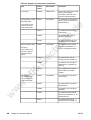
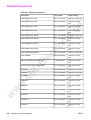
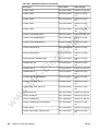
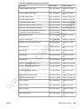
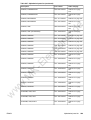
Table 8-1. Supplies and accessories
Product
number
M
Part
w
w
w
Firmware DIMMs
ENWW
Part number
Description
C9719-67901
16/64 programmed firmware
DIMM
Q3992-67901
16/128 programmed firmware
DIMM for the HP 3700dn and
HP 3700dtn bundles only
Flash Memory (DIMMs)
C4287A
C9665-67951
4 MB Flash DIMM
Memory upgrades
(DIMMs)
C7848A
C7848-67901
Synchronous 64 MB DIMM
(SDRAM)
C7850A
C7850-67901
Synchronous 128 MB DIMM
(SDRAM)
C9653A
C9653-67901
Synchronous 256 MB DIMM
(SDRAM)
Ordering parts
467
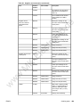
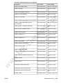
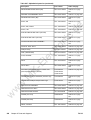
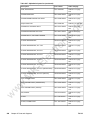
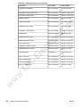
Table 8-1. Supplies and accessories (continued)
Part
Product
number
Part number
Description
Accessories
Q2486A
Q2486-67901
Optional 500-sheet paper feeder
(Tray 3) Internal (EIO)
connectivity for the HP Color
LaserJet 3700 series printer
Internal (EIO) I/O PCB
J6057A
J6057-69001
HP Jetdirect 615n internal print
server (10/100-TX, Ethernet, HISpeed USB 2.0)
(Exchange part)
HP Jetdirect 610n print server
(Token Ring)
J6058A
HP Jetdirect 680n 802.11b
wireless print server
Exchange
J7942-69001
El
e
Connectivity for the
HP Color LaserJet
3500/3550 series
printer
HP Jetdirect connectivity card
(USB, serial, and LocalTalk)
ct
ro
n
J7942A
ic
J4167A
J4135A
External (EX) I/O PCB
de
Connectivity for the
HP Color LaserJet
3700 series printer
HP Jetdirect 380x 802.11b
wireless print server (USB 1.1)
J6035B
HP Jetdirect 175x print server
(fast Ethernet, 10/100base Tx,
USB 1.1)
K-
J6061A
J6072A
w
w
w
M
External (EX)
connectivity for the
HP Color LaserJet
3700 series printer
468
Chapter 8 Parts and diagrams
HP Jetdirect en3700 external
print server (10/100base Tx,
USB 2.0 HI-speed) exchange
J3264A
HP bt1300 Bluetooth wireless
printer adapter (for USB or
parallel)
J7942-69001
HP Jetdirect 500x print server
(Token Ring)
J3265A
HP Jetdirect 500x print server
(fast Ethernet)
J3258B
HP Jetdirect 170x print server
(Ethernet)
J7942A
HP Jetdirect en3700 external
print server (10/100base Tx, HiSpeed USB 2.0)
J6061A
HP Jetdirect 380x 802.11b
wireless print server (USB 1.1)
ENWW
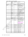
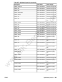
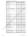
Table 8-1. Supplies and accessories (continued)
Product
number
J6035B
HP Jetdirect 175x print server
(fast Ethernet 10/100base Tx,
USB 1.1)
J6072A
HP bt1300 Bluetooth wireless
printer adapter (for USB or
parallel)
Q2670A
Black print cartridge for the
HP Color LaserJet 3500/3550
series printer
Q2671A
Cyan print cartridge for the
HP Color LaserJet 3500/3550
series printer
Q2673A
Q3658A
Q3655A
Magenta print cartridge for the
HP Color LaserJet 3500/3550
series printer
Q3658-69001
Image transfer kit
Q3655-69001
Image fuser kit (110-127V)
Q3656-69001
Image fuser kit (220-240V)
El
e
Q3656A
Yellow print cartridge for the
HP Color LaserJet 3500/3550
series printer
ct
ro
n
Q2672A
Q2670A
Black print cartridge for the
HP Color LaserJet 3700 series
printer
Q2681A
Cyan print cartridge for the
HP Color LaserJet 3700 series
printer
w
w
w
M
K-
Supplies for the 3700
series printer
Cables
Q2682A
Yellow print cartridge for the
HP Color LaserJet 3700 series
printer
Q2683A
Magenta print cartridge for the
HP Color LaserJet 3700 series
printer
Q3658A
Q3658-69001
Image transfer kit
Q3655A
Q3655-69001
Image fuser kit (110-127V)
Q3656A
Q3656-69001
Image fuser kit (220-240V)
C cable
C6518A
ENWW
Description
de
Supplies for the
HP Color LaserJet
3500/3550 series
printer
Part number
ic
Part
IEEE-1284 compliant parallel
cable, 3 m (approximately 10
feet) long, with 25-pin male/
micro 36-pin male ("C" size)
connector
8120-8485
USB (2-meter standard)
Ordering parts
469
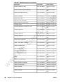
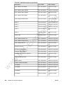
Table 8-1. Supplies and accessories (continued)
Part
Product
number
Part number
C6520A
USB 2.0 printer cable (3-meter)
Power cord
8120-6812
50 sheets HP Color LaserJet
Transparencies (letter)
C2936A
50 sheets HP Color LaserJet
Transparencies (A4)
Q2419A
HP LaserJet High Gloss paper
(letter)
C4179A
200 sheets HP LaserJet Soft
Gloss paper (letter)
C4179B
200 sheets HP LaserJet Soft
Gloss paper (A4)
Q1298B
ic
de
C2934A
Q1298A
HP LaserJet Tough paper (letter)
HP LaserJet Tough paper (A4)
HP Premium Choice LaserJet
paper (letter)
CHP410
HP Premium Choice LaserJet
paper (A4)
HPJ1124
HP LaserJet paper (letter)
CHP310
HP LaserJet paper (A4)
El
e
HPU1132
w
M
K-
Reference materials
Panel overlays
w
w
Ferrite Cores
470
Chapter 8 Parts and diagrams
AC power cord
ct
ro
n
Paper
Description
5851-1468
HP LaserJet Printer Family Print
Media Specification Guide
5021-0337
PCL/PJL Technical Reference
Package For downloadable
versions, go to
http://www.hp.com/support/
clj3550 or http://www.hp.com/
support/clj3700. When
connected, select Manuals.
Q1321-60117
Service training kit
Q1321-60115
Service support CD
5851-1782
Power supply cable
5851-1781
Formatter cable
Q1321-67901
French overlay
Q1321-67902
German overlay
Q1321-67903
Italian overlay
Q1321-67904
Spanish overlay
Q1321-67905
Danish overlay
ENWW
Table 8-1. Supplies and accessories (continued)
Part number
Description
Q1321-67906
Dutch overlay
Q1321-67907
Finnish overlay
Q1321-67908
Norwegian overlay
Q1321-67909
Portuguese overlay
Q1321-67910
Swedish overlay
Q1321-67911
Czech overlay
Q1321-67912
Hungarian overlay
Q1321-67913
Polish overlay
Q1321-67914
Russian overlay
Q1321-67915
Turkish overlay
Arabic overlay
ct
ro
n
Q1321-67916
de
Product
number
ic
Part
Greek overlay
Q1321-67918
Hebrew overlay
Q1321-67919
Japanese overlay
Q1321-67920
Korean overlay
Q1321-67921
Simplified Chinese overlay
Q1321-67922
Traditional Chinese overlay
5963-7863
HP LaserJet Printer Family
Paper Specifications Guide
5021-0337
PCL/PJL Technical Reference
Package CD-ROM
Q2670-67901
Black Print Cartridge-CLJ
3500/3550/3700
Q2670-67902
Black Print Cartridge-CLJ
3500/3550/3700 (Europe)
Q2671-67901
Cyan Print Cartridge-CLJ
3500/3550
Q2671-67902
Cyan Print Cartridge-CLJ
3500/3550 (Europe)
Q2681-67901
Cyan Print Cartridge-CLJ 3700
Q2681-67902
Cyan Print Cartridge-CLJ 3700
(Europe)
Q2672-67901
Yellow Print Cartridge-CLJ
3500/3550
Q2672-67902
Yellow Print Cartridge-CLJ
3500/3550 (Europe)
El
e
Q1321-67917
K-
Reference materials
w
w
w
M
Supplies
ENWW
Ordering parts
471
Table 8-1. Supplies and accessories (continued)
Part number
Description
Q2682-67901
Yellow Print Cartridge-CLJ 3700
Q2682-67901
Yellow Print Cartridge-CLJ 3700
(Europe)
Q2673-67901
Magenta Print Cartridge-CLJ
3500/3550
Q2673-67902
Magenta Print Cartridge-CLJ
3500/3550 (Europe)
Q2683-67901
Magenta Print Cartridge-CLJ
3700
Q2683-67902
Magenta Print Cartridge-CLJ
3700 (Europe)
5090-3379
de
Product
number
ic
Part
Toner cleaning cloth
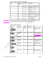
Table 8-2. Common fasteners
Description
Size
Part number
Use
SCREW, TP
M4X6
XA9-1450-000CN
Secures metal frame
panels to metal frame
panels.
El
e
Illustration
ct
ro
n
The only difference between the print cartridges listed above is that the Europe-only print
cartridges have different languages on the instruction sheet inside the box.
NOTE
M3X6
XA9-1477-000CN
Secures the drawer, cross
member, to the frame
(see Figure 8-11. Internal
components (4 of 4)).
SCREW, W/
WASHER, RS
M3X6
XA9-1461-000CN
Secures motor (M2) to the
frame.
SCREW W/
WASHER
M3X8
XA9-1420-000CN
Secures metal to metal
(ground wire, feed guide
rear two screws)
SCREW, W/
WASHER
M3X12
XA9-1452-000CN
Secures laser/scanner
assembly to the metal
frame.
SCREW, RS
M3X6
XA9-1499-000CN
Secures metal to metal.
SCREW, RS
M3X8
XA9-1445-000CN
secures any material
(except metal) to metal
w
w
w
M
K-
SCREW, W/
WASHER
472
Chapter 8 Parts and diagrams
ENWW
Table 8-2. Common fasteners (continued)
Part number
Use
SCREW, TP
XB4-7300-805CN
Secures sensor PCB to
plastic (environmental,
toner full, color
misregistration, and
media).
SCREW,TAPPING M4X10
,TRUSS HEAD
XB4-7401-005CN
Secures anything to
plastic.
SCREW,
STEPPED
M4X4.5
RC1-1624000CN
Secures the right side of
the pick-up/feed assembly
to the frame.
SCREW, S
M3X8
XA9-1500-000CN
Secures plastic to metal:
front door components,
rear swing guide rail,
components to center
frame (see Figure 8-16.
Lower Frame Assembly HP 3700 and
HP 3500/3550 (2 of 2))
de
Size
ic
Description
El
e
ct
ro
n
Illustration
Replacement parts configuration
K-
When the parts in the list below are replaced, specific tasks need to be performed. These
parts include:
Formatter and DC Controller replaced at the same time
●
Formatter (new and previously installed in another printer)
●
DC Controller (new and previously installed in another printer)
●
Media sensor (PS5)
●
Color Misregistration Sensor (PS12)
●
Laser Scanner Assembly
●
Fuser
●
Transfer unit (ITB assembly)
w
w
w
M
●
ENWW
Configuration procedures for these parts are described in the following sections.
Ordering parts
473
Illustrations and parts lists
w
w
w
M
K-
El
e
ct
ro
n
ic
de
The following illustrations and parts tables list the field replaceable units (FRUs) for this
printer. At the end of this chapter are two tables listing all of the parts shown in this chapter.
Alphabetical parts list lists the parts in alphabetical order, and Numerical parts list lists the
parts in numerical order by part number. Both tables list the appropriate figure in this chapter
where the part can be found.
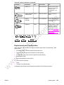
Figure 8-1.
478
Main parts (1 of 3)
Chapter 8 Parts and diagrams
ENWW
de
ic
ct
ro
n
El
e
KM
w
w
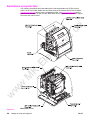
Main parts (2 of 3)
w
Figure 8-2.
ENWW
Illustrations and parts lists
479
de
w
w
M
K-
El
e
ct
ro
n
ic
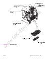
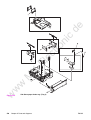
Main parts (3 of 3) 500-sheet paper feeder
Figure 8-3.
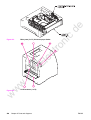
PCB locations (1 of 2)
w
Figure 8-4.
480
Chapter 8 Parts and diagrams
ENWW
Table 8-3. PCB locations
Description
Part number
Qty
1
DC controller PCB (HP3500)
RM1-0510-000CN
1
DC controller PCB (HP 3550)
RM1-2324-000CN
DC controller PCB (HP3700)
RM1-0506-000CN
2
Memory controller PCB
RM1-0508-000CN
1
3
High-voltage power supply PCBs
RM1-0505-000CN
1
4
Low-voltage power supply PCB (110-127V)
RK2-0157-000CN
RK2-0158-000CN
1
Formatter PCB (HP3500/3550)
Q1319-69001
1
Formatter PCB (HP3700)
Q1321-69001
5
Control panel PCB
RM1-0511-000CN
1
w
w
w
M
K-
El
e
6
Q1321-67924
ct
ro
n
Formatter Kit (HP3700)
ic
Low-voltage power supply PCB (220-240V)
de
Ref
ENWW
Illustrations and parts lists
481
de
ic
Paper Feeder PCB Assembly Location Diagram (2 of 2) R90 - 1
w
w
w
M
K-
El
e
ct
ro
n
Figure 8-5.
482
Chapter 8 Parts and diagrams
ENWW
Table 8-4. Paper feeder PCB Assembly Location diagram
Description
Part number
Qty
1
Paper feeder PCB
RM1-0768-000
1
w
w
w
M
K-
El
e
ct
ro
n
ic
de
Ref
ENWW
Illustrations and parts lists
483
de
ic
ct
ro
n
El
e
KM
w
w
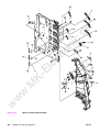
External covers and panels
w
Figure 8-6.
484
Chapter 8 Parts and diagrams
ENWW
Table 8-5. External covers and panels
Description
Part number
Qty
1
FRONT ROD LEFT ASS'Y
RM1-0443-000CN
1
2
FRONT ROD RIGHT ASS'Y
rm1-0444-000CN
1
3
TOP COVER ASS'Y
RM1-0465-020CN
1
4
LEFT COVER ASS'Y
RM1-0466-000CN
1
5
LEFT FRONT COVER ASS'Y
RM1-0467-000CN
1
6
FACE-UP TRAY ASS'Y
RM1-0468-000CN
1
7
COVER, RIGHT
RC1-1563-000CN
1
8
COVER, REAR
RC1-1565-000CN
1
9
COVER, JAM CLEARING
RC1-1566-000CN
10
PLATE, LOGO, RIGHT
RC1-1600-000CN
1
11
COVER, HINGE
12
1
RC1-2296-000CN
2
OPERATION PANEL ASS'Y
RM1-0511-000CM
1
13
CABLE, OPERATION PANEL
RM1-0489-000CN
1
14
TRAY, AUXILIARY
RC1-1555-000CN
1
15
COVER, DIMM
RC1-1562-000CN
1
16
SE RING (HP3500/3550)
XD2-2300-402CN
1
w
w
w
M
K-
El
e
ct
ro
n
ic
de
Ref
ENWW
Illustrations and parts lists
485
de
ic
ct
ro
n
El
e
KM
w
w
w
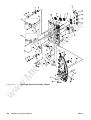
Figure 8-7.
486
Front door assembly
Chapter 8 Parts and diagrams
ENWW
Part number
Qty
FRONT DOOR ASSEMBLY
RM1-0463-000CN
1
1
MULTI-PURPOSE TRAY ASS'Y
RM1-0464-000CN
1
2
ROD, FRONT COVER, LEFT
RC1-1158-000CN
1
3
ROD, FRONT COVER, RIGHT
RC1-1159-000CN
1
4
LEVER, INTERLOCK SWITCH
RC1-1176-000CN
1
5
LEVER, ITB COUPLIN, 1
RC1-1247-000CN
1
6
LINK, MP HINGE, LEFT
RC1-1575-000CN
1
7
LINK, MP HINGE, RIGHT
RC1-1576-000CN
1
8
COVER, MP TRAY
RC1-1574-000CN
1
9
TRAY, EXPANSION, 1
RC1-2318-000CN
1
10
TRAY, EXPANSION, 2
RC1-2319-000CN
1
11
SPRING, TENSION
RC1-1407-000CN
2
ct
ro
n
w
w
w
M
K-
El
e
Ref
de
Description
ic
Table 8-6. Front door assembly
ENWW
Illustrations and parts lists
487
de
ic
ct
ro
n
El
e
KM
w
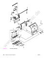
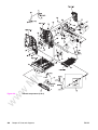
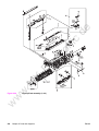
Internal components (1 of 4)
w
w
Figure 8-8.
488
Chapter 8 Parts and diagrams
ENWW
Description
Part number
Qty
1
PLATE, JOINT, RIGHT
RC1-1603-000CN
1
2
COVER, SCREW
RC1-1605-000CN
1
3
HIGH-VOLTAGE PCB ASS'Y
RM1-0505-000CN
1
4
RAIL, SWING, LEFT FRONT
RC1-1642-000CN
1
5
ARM, INTERLOCK SWITCH
RC1-1175-000CN
1
6
LOCK GUIDE RIGHT ASS'Y
RM1-0438-000CN
1
7
DRAWER CROSSMEMBER ASS'Y
RM1-0440-000CN
1
8
DEVELOPING CONTACT ASS'Y
RM1-0446-000CN
1
9
DAMPER UNIT, HINGE, LEFT
RC1-1572-000CN
1
10
DAMPER UNIT, HINGE, RIGHT
RC1-1573-000CN
1
11
TRANSFER CONTACT ASS'Y
RM1-0445-000CN
1
12
GUIDE, HARNESS
RC1-1342-000CN
1
13
SPRING, TENSION
RC1-1515-000CN
1
14
STOPPER, FRONT HINGE, LEFT
RL1-0215-000CN
1
15
STOPPER, HINGE, RIGHT
RL1-0216-000CN
1
16
CABLE, HIGH VOLTAGE
RM1-0485-000CN
1
17
RAIL, SWING, RIGHT FRONT
RC1-1661-000CN
1
w
w
w
M
K-
El
e
ct
ro
n
de
Ref
ic
Table 8-7. Internal components (1 of 4)
ENWW
Illustrations and parts lists
489
de
ic
ct
ro
n
El
e
KM
w
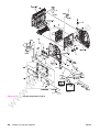
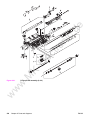
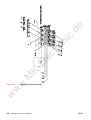
Internal components (2 of 4)
w
w
Figure 8-9.
490
Chapter 8 Parts and diagrams
ENWW
Table 8-8. Internal components (2 of 4)
Description
Part number
Qty
1
GEAR, 31T/19T
RC1-1284-000CN
1
2
GEAR, 54T/17T
RC1-1300-000CN
1
3
GEAR, 79T
RC1-1302-000CN
1
4
BUSHING
RC1-3249-000CN
1
5
COVER, MOTOR
RC1-1353-000CN
1
6
COVER, CONNECTOR
RC1-1488-000CN
1
7
GEAR, 25T
RC1-1497-000CN
1
8
SHAFT, DRIVE
RC1-1500-000CN
1
9
PLATE, MOUNTING
RC1-1355-000CN
10
RING, E
XD9-0136-000CN
2
11
BUSHING
12
ic
RC1-1630-000CN
1
PLATE, GROUNDING
RC1-1649-000CN
1
14
MOUNT, REGISTRATION CLUTCH
RC1-1186-000CN
1
15
CASSETTE PICK-UP ROLLER ASS'Y
RM1-0731-000CN
1
16
RING, E
XD9-0134-000CN
1
17
GEAR, 43T
RC1-1294-000CN
1
18
GEAR, 27T
RC1-1295-000CN
1
19
GEAR, 50T/90T
RC1-1224-000CN
1
20
LOW-VOLTAGE PCB ASS'Y (110-127V)
RK2-0157-000CN
1
LOW-VOLTAGE PCB ASS'Y (220-240V)
rk2-0158-000CN
1
PLATE, PAPER FEEDER DRIVE
RL1-0193-000CN
1
El
e
K-
M
21
22
GUIDE, CABLE
RC1-2334-000CN
1
23
GEAR, 39T
RC1-1281-000CN
1
24
GEAR, 26T/47T
RC1-1283-000CN
1
25
GEAR, 45T/25T
RC1-1286-000CN
1
26
HOLDER, GEAR
RC1-1287-000CN
1
27
GEAR, 38T
RC1-1288-000CN
1
28
GEAR, 104T/25T
RC1-1291-000CN
1
29
SPRING, TENSION
RC1-1292-000CN
1
30
GEAR, 20T
RC1-1493-000CN
1
31
GEAR, 26T/22T/20T
RC1-1298-000CN
1
32
COVER, CASSETTE
RC1-1665-000CN
1
w
w
w
ct
ro
n
1
20
ENWW
de
Ref
Illustrations and parts lists
491
Description
Part number
Qty
34
SUPPORT, PICK-UP GEAR
RL1-0217-000CN
1
35
RING, E
XD9-0137-000CN
1
36
CABLE, CPR CONNECTING
RM1-0482-000CN
1
37
CABLE, FORMATTER POWER SUPPLY
(HP3700)
RM1-0483-000CN
1
37
CABLE, FORMATTER POWER SUPPLY
(HP 3500/3550)
RM1-0498-000CN
1
38
CABLE, LEFT FRONT
RM1-0488-000CN
1
39
CLUTCH, ELECROMAGNETIC
RK2-0247-000CN
1
40
CLAMP, CABLE
WT2-5841-000CN
9
41
CONNECTOR, 2P
VS1-5057-002CN
1
42
SOLENOID
RK2-0141-000CN
1
w
w
w
M
K-
El
e
ct
ro
n
de
Ref
ic
Table 8-8. Internal components (2 of 4) (continued)
492
Chapter 8 Parts and diagrams
ENWW
de
ic
ct
ro
n
El
e
KM
w
w
w
ENWW
Illustrations and parts lists
493
de
ic
ct
ro
n
El
e
KM
w
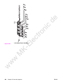
Internal components (3 of 4)
w
w
Figure 8-10.
494
Chapter 8 Parts and diagrams
ENWW
Table 8-9. Internal components (3 of 4)
Description
Part number
Qty
1
GUIDE, ROD, LEFT
RC1-1156-000CN
1
2
SENSOR UNIT, HUMIDITY
WP2-5156-000CN
1
3
SPRING, GROUNDING
RC1-1177-000CN
1
4
DEV. DISENGAGING DRIVE ASS'Y
RM1-0419-000CN
1
5
SHEET, CABLE RETAINING
RC1-2437-000CN
1
6
CABLE, ENVIRONMENT SENSOR
RM1-0493-000CN
1
7
GEAR, 120T/17T
RC1-1252-000CN
1
8
SWING ROD LEFT ASS'Y
RM1-0441-000CN
1
9
SWING ROD RIGHT ASS'Y
RM1-0442-000CN
10
DUCT, FAN
RC1-1345-000CN
1
11
DUCT, AIR, FRONT
12
FAN (HP3700)
12
FAN, (HP3500/3550)
13
CLAMP, CABLE
14
1
RC1-1350-000CN
1
RK2-0017-000CN
1
RK2-0153-000CN
1
WT2-5841-000CN
4
ARM, DRUM LOCK, LEFT
RC1-1170-000CN
1
15
SPRING, TENSION
RC1-1184-000CN
1
16
SPRING, TENSION
RC1-1628-000CN
3
17
ARM, DRUM LOCK, RIGHT
RC1-1361-000CN
1
18
SPRING, TENSION
RC1-1547-000CN
1
w
w
w
M
K-
El
e
ct
ro
n
ic
de
Ref
ENWW
Illustrations and parts lists
495
de
ic
ct
ro
n
El
e
KM
w
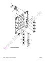
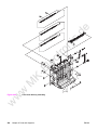
Internal components (4 of 4)
w
w
Figure 8-11.
496
Chapter 8 Parts and diagrams
ENWW
Description
Part number
Qty
1
GUIDE, CABLE
RC1-1181-000CN
1
2
GEAR, 86T/23T
RC1-1213-000CN
1
3
PLATE, JOINT, LEFT
RC1-1602-000CN
1
4
DC CONTROLLER PCB (HP3700)
RM1-0506-000CN
1
4
DC CONTROLLER PCB (HP3500/3550)
RM1-0510-000CN
1
5
FORMATTER PCB (HP3700) includes cage
Q1321-69001
5
FORMATTER PCB (HP3500/3550) includes
cage
Q1319-69001
1
6
COVER, CONTROLLER (HP3500/3550)
RC1-2236-000CN
1
7
BASE, CONTROLLER (HP3500/3550)
rc1-2235-000CN
1
8
DUCT, AIR
RC1-1354-000CN
1
9
PLATE, DC CONTROLLER SUPPORT
RC1-1348-000CN
1
10
ROD, POWER SWITCH
RC1-1347-000CN
1
11
LASER SCANNER ASS'Y
RM1-1142-000CN
1
12
BLOCK, TEST PRINT CONNECTING
RC1-1593-000CN
1
13
COVER, FMTR CABLE (HP3500/3550)
RC1-2364-000CN
1
14
LABEL, HIGH TEMP. CAUTION
RC1-2422-000CN
1
15
CLAMP, CABLE
WT2-0507-000CN
1
16
MICROSWITCH
RK2-0150-000CN
1
17
RAIL, SWING, RIGHT FRONT
RM1-0477-000CN
1
CLAMP, CABLE
WT2-5738-000CN
1
CABLE, FFC (HP3700)
RK2-0162-000CN
1
19
CABLE, FFC (HP3500/3550)
RK2-0179-000CN
1
20
CABLE, TM FFC
RK2-0163-000CN
1
21
CLAMP, CABLE
WT2-5754-000CN
2
22
CABLE, LASER FFC, 2
RK2-0165-000CN
1
23
CABLE, LASER FFC, 1
RK2-0164-000CN
1
24
CABLE, MAIN (HP3700)
RM1-0475-000CN
1
24
CABLE, MAIN (HP3500/3550)
RM1-0495-000CN
1
18
w
w
ENWW
ic
ct
ro
n
El
e
w
M
19
de
Ref
K-
Table 8-10. Internal components (4 of 4)
Illustrations and parts lists
497
de
ic
ct
ro
n
El
e
KM
w
w
w
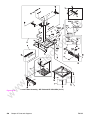
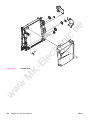
Figure 8-12.
498
Center frame assembly
Chapter 8 Parts and diagrams
ENWW
Description
Part number
Qty
1
BUSHING
RC1-1243-000CN
1
2
PHOTO-INTERRUPTER, TLP 1241
WG8-5362-000CN
1
3
CLAMP, CABLE
WT2-5841-000CN
1
4
MEMORY CONTROLLER PCB ASS'Y
RM1-0508-000CN
1
5
SPRING, TORSION
RC1-1328-000CN
1
6
HOLDER, SENSOR
RC1-1329-000CN
1
7
FLAG, SENSOR
RC1-1330-000CN
1
8
HOLDER, MEMORY CONTROLLER PCB
RC1-1343-000CN
1
9
PLATE, SHIELD
RC1-1349-000CN
1
10
COVER, LASER SHUTTER
RC1-1640-000CN
4
w
w
w
M
K-
El
e
ct
ro
n
de
Ref
ic
Table 8-11. Center Frame Assembly
ENWW
Illustrations and parts lists
499
de
ic
ct
ro
n
El
e
KM
w
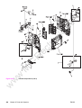
Main Right Side Plate Assembly / Motors
w
w
Figure 8-13.
500
Chapter 8 Parts and diagrams
ENWW
Description
Part number
Qty
1
LEVER, SWING LOCK, RIGHT
RC1-1148-000CN
1
2
SPRING, TENSION
RC1-1149-000CN
1
3
MOTOR (M5)
RK2-0139-000CN
1
4
GEAR, 59T
RC1-1231-000CN
2
5
BUSHING
RC1-1218-000CN
4
6
GEAR, 74T
RC1-3240-000CN
1
7
GEAR, 90T/28T
RC1-1229-000CN
1
8
GEAR, 74T
RC1-1230-000CN
4
9
GEAR, 69T
RC1-1233-000CN
1
10
GEAR, 29T
RC1-1234-000CN
4
11
PLATE, REINFORCEMENT
RC1-1242-000CN
4
12
BUSHING
RC1-1243-000CN
2
13
BUSHING
RC1-1244-000CN
4
14
ARM, DRUM LOCK, RIGHT
RC1-1246-000CN
1
15
LEVER, I.T.B. COUPLING
RC1-1248-000CN
1
16
SPRING, TENSION
RC1-1259-000CN
4
17
SPRING, TENSION
RC1-1260-000CN
1
18
MOTOR (M1)
RK2-0137-000CN
1
19
PLATE, DRIVE
RC1-1277-000CN
1
MOTOR (M2)
RK2-0138-000CN
1
BUSHING
RC1-1310-000CN
1
ct
ro
n
El
e
M
21
K-
20
de
Ref
ic
Table 8-12. Main Right Side Plate Assembly / Motors
ARM, DRUM LOCK, RIGHT
RC1-1362-000CN
1
23
SPRING, GROUNDING
RC1-1537-000CN
3
24
ARM, DRUM LOCK, RIGHT
RC1-1545-000CN
1
25
STOPPER, ARM, RIGHT
RC1-1546-000CN
1
26
DEVELOPING MOTOR ASS'Y (M4)
RM1-0737-000CN
1
27
SPRING, TENSION
RC1-1548-000CN
3
28
PLATE, GROUNDING
RC1-1629-000CN
1
29
RAIL, SWING, RIGHT REAR
RC1-1662-000CN
1
30
PLATE, GROUNDING
RC1-2294-000CN
1
31
CONNECTOR, SNAP TIGHT
VS1-6910-012CN
1
32
STOPPER, ARM, RIGHT
RC1-2339-000CN
2
w
w
w
22
ENWW
Illustrations and parts lists
501
Table 8-12. Main Right Side Plate Assembly / Motors (continued)
Description
Part number
Qty
33
PLATE
RL1-0189-000CN
1
34
PIN, DOWEL
XD9-0120-000CN
8
35
CONNECTOR, 16P
VS1-6492-016CN
1
36
RING, E
XD9-0136-000CN
3
37
DRUM MOTOR ASS'Y (M3)
RM1-0733-000CN
1
38
PAD, CUSHION
RC1-2330-000CN
3
39
DAMPER UNIT, MP PICK-UP
RC1-1038-000CN
1
40
RINIG, GRIP
XD2-2100-602CN
1
w
w
w
M
K-
El
e
ct
ro
n
ic
de
Ref
502
Chapter 8 Parts and diagrams
ENWW
de
ic
ct
ro
n
El
e
KM
w
w
w
ENWW
Illustrations and parts lists
503
de
ic
ct
ro
n
El
e
KM
w
w
w
Figure 8-14.
504
Main Left Side Plate Assembly
Chapter 8 Parts and diagrams
ENWW
Description
Part number
Qty
1
HOLDER, SENSOR
RC1-1049-000CN
1
2
LENS
RC1-1050-000CN
2
3
PLATE, CONTACT
RC1-1151-000CN
1
4
PLATE, CONTACT
RC1-1152-000CN
1
5
PLATE, CONTACT
RC1-1153-000CN
1
6
PLATE, CONTACT
RC1-1155-000CN
1
7
ARM, DRUM LOCK, LEFT
RC1-1169-000CN
1
8
CONNECTOR, SNAP TIGHT, W
VS1-6492-010CN
1
9
SENSOR UNIT, TCU FULL DETECT
RM1-0509-000CN
1
10
SPRING, TENSION
RC1-1185-000CN
3
11
ARM, DRUM LOCK, LEFT
RC1-1622-000CN
1
12
ARM, DRUM LOCK, LEFT
RC1-1623-000CN
1
13
STRAP, DAMPER
RC1-1625-000CN
3
14
STOPPER, ARM, LEFT
RC1-1626-000CN
1
15
STOPPER, ARM, LEFT
RC1-1627-000CN
2
16
PAD, CUSHION
RC1-2330-000CN
3
17
RAIL, SWING, LEFT REAR
RC1-1641-000CN
1
18
LEVER, SWING LOCK, LEFT
RC1-1647-000CN
1
19
SPRING, TENSION
RC1-1648-000CN
1
PAD, CUSHION
RC12331-000CN
3
PHOTO-INTERRUPTER, TLP1241
WG8-5362-000CN
1
ct
ro
n
El
e
w
w
w
M
21
K-
20
de
Ref
ic
Table 8-13. Main Left Side Plate Assembly
ENWW
Illustrations and parts lists
505
de
ic
ct
ro
n
El
e
KM
w
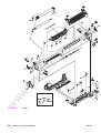
Lower Frame Assembly - HP 3700 and HP 3500/3550 (1 of 2)
w
w
Figure 8-15.
506
Chapter 8 Parts and diagrams
ENWW
de
ic
ct
ro
n
El
e
KM
w
w
w
ENWW
Illustrations and parts lists
507
de
ic
ct
ro
n
El
e
KM
w
w
Lower Frame Assembly - HP 3700 and HP 3500/3550 (2 of 2)
w
Figure 8-16.
508
Chapter 8 Parts and diagrams
ENWW
Description
Part number
Qty
1
CLUTCH, MECHANICAL
RB2-6324-000CNN
1
2
HOLDER, SENSOR
RC1-1496-000CN
1
3
LEVER, SENSOR
RC1-1514-000CN
1
4
GUIDE, CABLE
RC1-2322-000CN
1
5
GUIDE, CABLE
RC1-2323-000CN
1
6
GUIDE, CASSETTE, LEFT
RC1-1491-000CN
1
7
MOUNT, SOLENOID (HP3700)
RL1-0203-000CN
1
7
MOUNT, SOLENOID (HP3500/3550)
RC1-1511-000CN
1
8
DUPLEX GUIDE ASS'Y (HP3700)
RM1-0458-000CN
1
9
FOOT ASS'Y
RM1-0459-000CN
10
PAPER FEED ASS'Y
ic
2
RM1-0460-000CN
1
11
DUPLEX FEED GUIDE ASS'Y (HP3700)
RM1-0461-000CN
1
12
POSITION GUIDE ASS'Y (HP3700)
RM1-0462-000CN
1
13
CASSETTE GUIDE RIGHT ASS'Y
RM1-0736-000CN
1
14
COVER, LOWER FRAME (HP3700)
RC1-2237-000CN
1
15
SUPPORT, FOOT, REAR
RC1-2428-000CN
2
16
PHOTO-INTERRUPTER, TLP1241 (HP3700)
WG8-5362-000CN
3
16
PHOTO-INTERRUPTER, TLP1241
(HP3500/3550)
WG8-5362-000CN
1
17
CABLE, FRAME, LOWER (HP3700)
RM1-0478-000CN
1
CABLE, FRAME, LOWER (HP3500/3550)
RM1-0497-000CN
1
GUIDE, CABLE
RC1-1306-000CN
1
PLATE, CONNECTING
RC1-1637-000CN
1
20
CABLE, OPTION CONNECTING (HP3700)
RM1-0476-000CN
1
20
CABLE, OPTION CONNECTING
(HP3500/3550)
RM1-0496-000CN
1
21
CONNECTOR, 6P (HP3500/3550)
VS1-6176-006CN
1
22
PLATE, GROUNDING (HP3500/3550)
RC1-1509-000CN
1
23
SPRING, LEAF (HP3500/3550)
RC1-1508-000CN
1
24
GUIDE, CASSETTE, RIGHT (HP3500)
RC1-1492-000CN
1
25
SOLENOID
RK2-0143-000CN
1
26
GUIDE, DUPLEXING (HP3700)
RC1-1613-000CN
1
18
w
w
ct
ro
n
El
e
w
M
19
K-
17
ENWW
de
Ref
Illustrations and parts lists
509
de
ic
w
w
w
M
K-
El
e
ct
ro
n
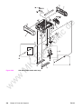
Image Drive Assembly
Figure 8-17.
510
Chapter 8 Parts and diagrams
ENWW
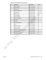
Table 8-14. Image drive assembly
Ref
Part number
Qty
IMAGE DRIVE ASSEMBLY
RM1-0415-040CN
1
CLUTCH, ELECTROMAGNETIC
RK2-0248-000CN
1
w
w
w
M
K-
El
e
ct
ro
n
ic
de
1
Description
ENWW
Illustrations and parts lists
511
de
w
w
w
M
K-
El
e
ct
ro
n
ic
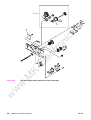
Developing Disengaging Assembly
Figure 8-18.
512
Chapter 8 Parts and diagrams
ENWW
Table 8-15. Developing Disengaging Assembly
Description
Part number
Qty
DEVELOPING DISENGAGING ASSEMBLY
RM1-0434-000CN
1
1
CLUTCH, ELECTROMAGNETIC
RK2-0176-000CN
1
2
RING, E
XD9-0135-000CN
1
w
w
w
M
K-
El
e
ct
ro
n
ic
de
Ref
ENWW
Illustrations and parts lists
513
de
ic
ct
ro
n
El
e
KM
Tray 2 (cassette)
w
w
w
Figure 8-19.
514
Chapter 8 Parts and diagrams
ENWW
Table 8-16. Tray 2 (cassette)
Description
Part number
Qty
TRAY 2 (CASSETTE)
RM1-0470-000CN
1
1
PLATE, END
RB2-3003-040CN
1
2
SPRING, COMPRESSION
RS6-2021-000CN
1
3
PAD, SEPARATION
RC1-0954-000CN
1
w
w
w
M
K-
El
e
ct
ro
n
ic
de
Ref
ENWW
Illustrations and parts lists
515
de
ic
ct
ro
n
El
e
KM
w
Pick-up/Feed assembly (1 of 2)
w
w
Figure 8-20.
516
Chapter 8 Parts and diagrams
ENWW
de
ic
ct
ro
n
El
e
KM
w
w
w
ENWW
Illustrations and parts lists
517
de
ic
ct
ro
n
El
e
KM
Pick-up/Feed assembly (2 of 2)
w
w
w
Figure 8-21.
518
Chapter 8 Parts and diagrams
ENWW
Part number
Qty
PICK-UP/FEED ASS'Y (HP3700)
RM1-0449-000CN
1
PICK-UP/FEED ASS'Y (HP3500/3550)
RM1-0760-000CN
1
1
SEPARATION PAD ASS'Y
RM1-0739-000CN
1
2
SOLENOID
RK2-0145-000CN
1
3
TRANSFER ROLLER ASS'Y
RM1-0740-000CN
1
4
CLUTCH, MECHANICAL
RC1-1433-000CN
1
5
LEVER, SENSOR
RC1-1456-000CN
1
6
SPRING, TORSION
RC1-1464-000CN
1
7
PAD, SEPARATION
RC1-0939-000
1
8
ROLLER, PICK-UP
RC1-1535-000CN
1
9
COLOR MIS-REG. SENSOR ASS'Y
RM1-0451-000CN
1
10
MEDIA SENSOR ASS'Y
RM1-0452-000CN
1
11
PHOTO-INTERRUPTER, TLP1241
WG8-5362-000CN
3
12
SOLENOID
RK2-0141-000CN
1
13
PICK-UP FEED ASSY
RM1-0456-000CN
1
ct
ro
n
w
w
w
M
K-
El
e
Ref
de
Description
ic
Table 8-17. Pick-up/Feed assembly
ENWW
Illustrations and parts lists
519
de
ic
ct
ro
n
El
e
KM
w
Tray 2 (cassette) pick-up assembly
w
w
Figure 8-22.
520
Chapter 8 Parts and diagrams
ENWW
Table 8-18. Tray 2 (cassette) pick-up assembly
Description
Part number
Qty
1
PHOTO-INTERRUPTER, TLP1241
WG8-5362-000CN
1
w
w
w
M
K-
El
e
ct
ro
n
ic
de
Ref
ENWW
Illustrations and parts lists
521
de
ic
ct
ro
n
El
e
KM
w
Face-down delivery assembly
w
w
Figure 8-23.
522
Chapter 8 Parts and diagrams
ENWW
Table 8-19. Face-down delivery assembly
Ref
Part number
Qty
FACE-DOWN DELIVERY ASSEMBLY
RM1-0469-000CN
1
PHOTO-INTERRUPTER, TLP1241
WG8-5362-000CN
1
w
w
w
M
K-
El
e
ct
ro
n
ic
de
1
Description
ENWW
Illustrations and parts lists
523
de
ic
ct
ro
n
El
e
K-
Transfer Unit
w
w
w
M
Figure 8-24.
524
Chapter 8 Parts and diagrams
ENWW
Table 8-20. Transfer unit
Description
Part number
Qty
1
TRANSFER UNIT
Q3658-69001
1
w
w
w
M
K-
El
e
ct
ro
n
ic
de
Ref
ENWW
Illustrations and parts lists
525
de
ic
ct
ro
n
El
e
KM
w
Right Swing Frame Assembly
w
w
Figure 8-25.
526
Chapter 8 Parts and diagrams
ENWW
Table 8-21. Right Swing Frame Assembly
Description
Part number
Qty
1
RIGHT SWING FRAME ASS'Y
RM1-0437-000CN
1
w
w
w
M
K-
El
e
ct
ro
n
ic
de
Ref
ENWW
Illustrations and parts lists
527
de
ic
ct
ro
n
El
e
Left Swing Frame Assembly
w
w
w
M
K-
Figure 8-26.
528
Chapter 8 Parts and diagrams
ENWW
Table 8-22. Left swing frame assembly
Description
Part number
Qty
LEFT SWING FRAME ASS'Y
RM1-0439-000CN
1
w
w
w
M
K-
El
e
ct
ro
n
ic
de
Ref
ENWW
Illustrations and parts lists
529
de
ic
ct
ro
n
El
e
KM
w
w
w
Figure 8-27.
530
Fuser
Chapter 8 Parts and diagrams
ENWW
Table 8-23. Fuser assembly
Description
Part number
Qty
FUSER (110-127V)
Q3655-69001
1
FUSER (220-240V)
Q3656-69001
1
w
w
w
M
K-
El
e
ct
ro
n
ic
de
Ref
ENWW
Illustrations and parts lists
531
de
ic
ct
ro
n
El
e
KM
500-Sheet paper feeder main body
w
w
w
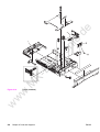
Figure 8-28.
532
Chapter 8 Parts and diagrams
ENWW
Table 8-24. 500-Sheet paper feeder main body
Description
Part number
Qty
1
COVER, FRONT
RC1-2178-000CN
1
2
COVER, REAR
RC1-2179-000CN
1
3
COVER, LEFT
RC1-2180-000CN
1
4
COVER, LOWER, LEFT
RB2-3489-000CN
1
5
ARM, SENSOR
RB2-6448-000CN
1
6
SPRING, LEAF
RB2-6450-000CN
1
7
CROSSMEMBER
RB2-6452-000CN
2
8
COVER, SENSOR
RB2-6453-000CN
1
9
PLATE, GROUNDING
RC1-2175-000CN
10
BUSHING
RC1-2182-000CN
1
11
BUSHING
12
1
RC1-2192-000CN
1
PLATE, GROUNDING
RC1-2280-000CN
1
13
FOOT
RC1-2165-000CN
4
14
SUB ROLLER ASS'Y
RM1-0709-000CN
1
15
CABLE, DRAWER
RM1-0769-000CN
1
16
CABLE, SENSOR
RM1-0770-000CN
1
17
CASSETTE PICK-UP ROLLER ASS'Y
RM1-0731-000CN
1
18
CONNECTOR, 6P
VS1-6175-006CN
1
19
PHOTO-INTERRUPTER
WG8-5571-000CN
1
w
w
w
M
K-
El
e
ct
ro
n
ic
de
Ref
ENWW
Illustrations and parts lists
533
de
ic
ct
ro
n
El
e
KM
500-Sheet paper feeder paper pick-up drive assembly
w
w
w
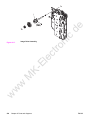
Figure 8-29.
534
Chapter 8 Parts and diagrams
ENWW
Table 8-25. 500-Sheet paper feeder paper pick-up drive assembly
Description
Part number
Qty
PAPER PICK-UP DRIVE ASS'Y
RM1-0701-000CN
1
1
SWING ASS'Y
RM1-0707-000CN
1
2
PAPER FEEDER DRIVER PCB ASS'Y
RM1-0768-000CN
1
w
w
w
M
K-
El
e
ct
ro
n
ic
de
Ref
ENWW
Illustrations and parts lists
535
de
ic
ct
ro
n
El
e
KM
w
w
w
Figure 8-30.
536
500-Sheet paper feeder tray (Tray 3)
Chapter 8 Parts and diagrams
ENWW
Table 8-26. 500-Sheet paper feeder tray (Tray 3)
Description
Part number
Qty
PAPER TRAY 3, 500-SHEET FEEDER
RM1-0705-000CN
1
1
PLATE, END
RB2-6469-000CN
1
2
SPRING, COMPRESSION
RC1-2191-000CN
1
3
PAPER SEPARATION PAD ASS'Y
RM1-0827-000CN
1
w
w
w
M
K-
El
e
ct
ro
n
ic
de
Ref
ENWW
Illustrations and parts lists
537
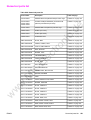
Alphabetical parts list
Table 8-27. Alphabetical parts list
Part number
Table and page
ARM, DRUM LOCK, LEFT
RC1-1170-000CN
Table 8-9 on page 495
ARM, DRUM LOCK, LEFT
RC1-1169-000CN
Table 8-13 on page
505
ARM, DRUM LOCK, LEFT
RC1-1622-000CN
Table 8-13 on page
505
ARM, DRUM LOCK, LEFT
RC1-1623-000CN
Table 8-13 on page
505
ARM, DRUM LOCK, RIGHT
RC1-1361-000CN
Table 8-9 on page 495
ARM, DRUM LOCK, RIGHT
RC1-1246-000CN
Table 8-12 on page
501
ic
ct
ro
n
ARM, DRUM LOCK, RIGHT
de
Description
RC1-1362-000CN
Table 8-12 on page
501
RC1-1545-000CN
Table 8-12 on page
501
RC1-1175-000CN
Table 8-7 on page 489
RB2-6448-000CN
Table 8-24 on page
533
BASE, CONTROLLER (HP3500/3550)
rc1-2235-000CN
Table 8-10 on page
497
BLOCK, TEST PRINT CONNECTING
RC1-1593-000CN
Table 8-10 on page
497
BUSHING
RC1-3249-000CN
Table 8-8 on page 491
BUSHING
RC1-1630-000CN
Table 8-8 on page 491
BUSHING
RC1-1243-000CN
Table 8-11 on page
499
BUSHING
RC1-1218-000CN
Table 8-12 on page
501
BUSHING
RC1-1243-000CN
Table 8-12 on page
501
BUSHING
RC1-1244-000CN
Table 8-12 on page
501
BUSHING
RC1-1310-000CN
Table 8-12 on page
501
BUSHING
RC1-2182-000CN
Table 8-24 on page
533
BUSHING
RC1-2192-000CN
Table 8-24 on page
533
ARM, DRUM LOCK, RIGHT
ARM, INTERLOCK SWITCH
w
w
w
M
K-
El
e
ARM, SENSOR
538
Chapter 8 Parts and diagrams
ENWW
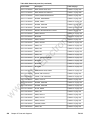
Table 8-27. Alphabetical parts list (continued)
Part number
Table and page
CABLE, CPR CONNECTING
RM1-0482-000CN
Table 8-8 on page 492
CABLE, DRAWER
RM1-0769-000CN
Table 8-24 on page
533
CABLE, ENVIRONMENT SENSOR
RM1-0493-000CN
Table 8-9 on page 495
CABLE, FFC (HP3500/3550)
RK2-0179-000CN
Table 8-10 on page
497
CABLE, FFC (HP3700)
RK2-0162-000CN
Table 8-10 on page
497
CABLE, FORMATTER POWER SUPPLY (HP3700)
RM1-0483-000CN
Table 8-8 on page 492
CABLE, FORMATTER POWER SUPPLY
(HP 3500/3550)
RM1-0498-000CN
Table 8-8 on page 492
CABLE, FRAME, LOWER (HP3500/3550)
RM1-0497-000CN
Table 8-13 on page
509
CABLE, HIGH VOLTAGE
RM1-0485-000CN
Table 8-7 on page 489
RK2-0164-000CN
Table 8-10 on page
497
RK2-0165-000CN
Table 8-10 on page
497
CABLE, LEFT FRONT
RM1-0488-000CN
Table 8-8 on page 492
CABLE, MAIN (HP3500/3550)
RM1-0495-000CN
Table 8-10 on page
497
CABLE, MAIN (HP3700)
RM1-0475-000CN
Table 8-10 on page
497
CABLE, OPERATION PANEL
RM1-0489-000CN
Table 8-5 on page 485
CABLE, OPTION CONNECTING (HP3500/3550)
RM1-0496-000CN
Table 8-13 on page
509
CABLE, OPTION CONNECTING (HP3700)
RM1-0476-000CN
Table 8-13 on page
509
CABLE, SENSOR
RM1-0770-000CN
Table 8-24 on page
533
CABLE, TM FFC
RK2-0163-000CN
Table 8-10 on page
497
CASSETTE GUIDE RIGHT ASS'Y
RM1-0736-000CN
Table 8-13 on page
509
CASSETTE PICK-UP ROLLER ASS'Y
RM1-0731-000CN
Table 8-8 on page 491
CASSETTE PICK-UP ROLLER ASS'Y
RM1-0731-000CN
Table 8-24 on page
533
CLAMP, CABLE
WT2-5841-000CN
Table 8-8 on page 492
El
e
K-
M
w
w
ic
ct
ro
n
RM1-0478-000CN
CABLE, LASER FFC, 2
w
Table 8-13 on page
509
CABLE, FRAME, LOWER (HP3700)
CABLE, LASER FFC, 1
ENWW
de
Description
Alphabetical parts list
539
Table 8-27. Alphabetical parts list (continued)
Part number
Table and page
CLAMP, CABLE
WT2-5841-000CN
Table 8-9 on page 495
CLAMP, CABLE
WT2-0507-000CN
Table 8-10 on page
497
CLAMP, CABLE
WT2-5738-000CN
Table 8-10 on page
497
CLAMP, CABLE
WT2-5754-000CN
Table 8-10 on page
497
CLAMP, CABLE
WT2-5841-000CN
Table 8-11 on page
499
CLUTCH, ELECROMAGNETIC
RK2-0247-000CN
Table 8-8 on page 492
CLUTCH, ELECTROMAGNETIC
RK2-0248-000CN
CLUTCH, ELECTROMAGNETIC
RK2-0176-000CN
Table 8-13 on page
509
RC1-1433-000CN
Table 8-17 on page
519
COLOR MIS-REG. SENSOR ASS'Y
RM1-0451-000CN
Table 8-17 on page
519
CONNECTOR, 16P
VS1-6492-016CN
Table 8-12 on page
502
CONNECTOR, 2P
VS1-5057-002CN
Table 8-8 on page 492
CONNECTOR, 6P
VS1-6175-006CN
Table 8-24 on page
533
CONNECTOR, 6P (HP3500/3550)
VS1-6176-006CN
Table 8-13 on page
509
CONNECTOR, SNAP TIGHT
VS1-6910-012CN
Table 8-12 on page
501
CONNECTOR, SNAP TIGHT, W
VS1-6492-010CN
Table 8-13 on page
505
Control panel PCB
RM1-0511-000CN
Table 8-3 on page 481
COVER, CASSETTE
RC1-1665-000CN
Table 8-8 on page 491
COVER, CONNECTOR
RC1-1488-000CN
Table 8-8 on page 491
COVER, CONTROLLER (HP3500/3550)
RC1-2236-000CN
Table 8-10 on page
497
COVER, DIMM
RC1-1562-000CN
Table 8-5 on page 485
COVER, FMTR CABLE (HP3500/3550)
RC1-2364-000CN
Table 8-10 on page
497
El
e
K-
M
w
w
w
Table 8-15 on page
513
RB2-6324-000CNN
CLUTCH, MECHANICAL
540
Table 8-14 on page
511
ic
ct
ro
n
CLUTCH, MECHANICAL
de
Description
Chapter 8 Parts and diagrams
ENWW
Table 8-27. Alphabetical parts list (continued)
Part number
Table and page
COVER, FRONT
RC1-2178-000CN
Table 8-24 on page
533
COVER, HINGE
RC1-2296-000CN
Table 8-5 on page 485
COVER, JAM CLEARING
RC1-1566-000CN
Table 8-5 on page 485
COVER, LASER SHUTTER
RC1-1640-000CN
Table 8-11 on page
499
COVER, LEFT
RC1-2180-000CN
Table 8-24 on page
533
COVER, LOWER FRAME (HP3700)
RC1-2237-000CN
Table 8-13 on page
509
COVER, LOWER, LEFT
RB2-3489-000CN
Table 8-24 on page
533
COVER, MOTOR
RC1-1353-000CN
ic
ct
ro
n
COVER, MP TRAY
Table 8-6 on page 487
RC1-1565-000CN
Table 8-5 on page 485
RC1-2179-000CN
Table 8-24 on page
533
RC1-1563-000CN
Table 8-5 on page 485
RC1-1605-000CN
Table 8-7 on page 489
COVER, SENSOR
RB2-6453-000CN
Table 8-24 on page
533
CROSSMEMBER
RB2-6452-000CN
Table 8-24 on page
533
DAMPER UNIT, HINGE, LEFT
RC1-1572-000CN
Table 8-7 on page 489
DAMPER UNIT, HINGE, RIGHT
RC1-1573-000CN
Table 8-7 on page 489
DAMPER UNIT, MP PICK-UP
RC1-1038-000CN
Table 8-12 on page
502
DC controller PCB (HP3500) DC controller PCB (HP
3550) DC controller PCB (HP3700)
RM1-0510-000CN
RM1-2324-000CN
RM1-0506-000CN
Table 8-3 on page 481
DC CONTROLLER PCB (HP3500/3550)
RM1-0510-000CN
Table 8-10 on page
497
DC CONTROLLER PCB (HP3700)
RM1-0506-000CN
Table 8-10 on page
497
DEV. DISENGAGING DRIVE ASS'Y
RM1-0419-000CN
Table 8-9 on page 495
DEVELOPING CONTACT ASS'Y
RM1-0446-000CN
Table 8-7 on page 489
DEVELOPING DISENGAGING ASSEMBLY
RM1-0434-000CN
Table 8-15 on page
513
COVER, REAR
COVER, RIGHT
w
w
M
K-
El
e
COVER, SCREW
w
Table 8-8 on page 491
RC1-1574-000CN
COVER, REAR
ENWW
de
Description
Alphabetical parts list
541
Table 8-27. Alphabetical parts list (continued)
Part number
Table and page
DEVELOPING MOTOR ASS'Y (M4)
RM1-0737-000CN
Table 8-12 on page
501
DRAWER CROSSMEMBER ASS'Y
RM1-0440-000CN
Table 8-7 on page 489
DRUM MOTOR ASS'Y (M3)
RM1-0733-000CN
Table 8-12 on page
502
DUCT, AIR
RC1-1354-000CN
Table 8-10 on page
497
DUCT, AIR, FRONT
RC1-1350-000CN
Table 8-9 on page 495
DUCT, FAN
RC1-1345-000CN
Table 8-9 on page 495
DUPLEX FEED GUIDE ASS'Y (HP3700)
RM1-0461-000CN
Table 8-13 on page
509
DUPLEX GUIDE ASS'Y (HP3700)
RM1-0458-000CN
ic
ct
ro
n
RM1-0469-000CN
Table 8-19 on page
523
FACE-UP TRAY ASS'Y
RM1-0468-000CN
Table 8-5 on page 485
RK2-0017-000CN
Table 8-9 on page 495
RK2-0153-000CN
Table 8-9 on page 495
RC1-1330-000CN
Table 8-11 on page
499
RC1-2165-000CN
Table 8-24 on page
533
RM1-0459-000CN
Table 8-13 on page
509
Q1319-69001
Q1321-69001
Q1321-67924
Table 8-3 on page 481
FORMATTER PCB (HP3500/3550) includes cage
Q1319-69001
Table 8-10 on page
497
FORMATTER PCB (HP3700) includes cage
Q1321-69001
Table 8-10 on page
497
FRONT DOOR ASSEMBLY
RM1-0463-000CN
Table 8-6 on page 487
FRONT ROD LEFT ASS'Y
RM1-0443-000CN
Table 8-5 on page 485
FRONT ROD RIGHT ASS'Y
rm1-0444-000CN
Table 8-5 on page 485
FUSER (110-127V)
Q3655-69001
Table 8-23 on page
531
FUSER (220-240V)
Q3656-69001
Table 8-23 on page
531
GEAR, 104T/25T
RC1-1291-000CN
Table 8-8 on page 491
FAN, (HP3500/3550)
FOOT
K-
FOOT ASS'Y
El
e
FLAG, SENSOR
w
w
M
Formatter PCB (HP3500/3550) Formatter PCB
(HP3700) Formatter Kit (HP3700)
w
Table 8-13 on page
509
FACE-DOWN DELIVERY ASSEMBLY
FAN (HP3700)
542
de
Description
Chapter 8 Parts and diagrams
ENWW
Table 8-27. Alphabetical parts list (continued)
Part number
Table and page
GEAR, 120T/17T
RC1-1252-000CN
Table 8-9 on page 495
GEAR, 20T
RC1-1493-000CN
Table 8-8 on page 491
GEAR, 25T
RC1-1497-000CN
Table 8-8 on page 491
GEAR, 26T/22T/20T
RC1-1298-000CN
Table 8-8 on page 491
GEAR, 26T/47T
RC1-1283-000CN
Table 8-8 on page 491
GEAR, 27T
RC1-1295-000CN
Table 8-8 on page 491
GEAR, 29T
RC1-1234-000CN
Table 8-12 on page
501
GEAR, 31T/19T
RC1-1284-000CN
Table 8-8 on page 491
GEAR, 38T
RC1-1288-000CN
Table 8-8 on page 491
GEAR, 39T
RC1-1281-000CN
Table 8-8 on page 491
GEAR, 43T
RC1-1294-000CN
Table 8-8 on page 491
RC1-1286-000CN
Table 8-8 on page 491
RC1-1224-000CN
Table 8-8 on page 491
RC1-1300-000CN
Table 8-8 on page 491
RC1-1231-000CN
Table 8-12 on page
501
RC1-1233-000CN
Table 8-12 on page
501
RC1-3240-000CN
Table 8-12 on page
501
RC1-1230-000CN
Table 8-12 on page
501
GEAR, 79T
RC1-1302-000CN
Table 8-8 on page 491
GEAR, 86T/23T
RC1-1213-000CN
Table 8-10 on page
497
GEAR, 90T/28T
RC1-1229-000CN
Table 8-12 on page
501
GUIDE, CABLE
RC1-2334-000CN
Table 8-8 on page 491
GUIDE, CABLE
RC1-1181-000CN
Table 8-10 on page
497
GUIDE, CABLE
RC1-2322-000CN
Table 8-13 on page
509
GUIDE, CABLE
RC1-2323-000CN
Table 8-13 on page
509
GUIDE, CABLE
RC1-1306-000CN
Table 8-13 on page
509
ct
ro
n
ic
de
Description
GEAR, 45T/25T
GEAR, 50T/90T
GEAR, 54T/17T
GEAR, 69T
GEAR, 74T
w
w
w
M
K-
GEAR, 74T
El
e
GEAR, 59T
ENWW
Alphabetical parts list
543
Table 8-27. Alphabetical parts list (continued)
Part number
Table and page
GUIDE, CASSETTE, LEFT
RC1-1491-000CN
Table 8-13 on page
509
GUIDE, CASSETTE, RIGHT (HP3500)
RC1-1492-000CN
Table 8-13 on page
509
GUIDE, DUPLEXING (HP3700)
RC1-1613-000CN
Table 8-13 on page
509
GUIDE, HARNESS
RC1-1342-000CN
Table 8-7 on page 489
GUIDE, ROD, LEFT
RC1-1156-000CN
Table 8-9 on page 495
HIGH-VOLTAGE PCB ASS'Y
RM1-0505-000CN
Table 8-7 on page 489
High-voltage power supply PCBs
RM1-0505-000CN
Table 8-3 on page 481
HOLDER, GEAR
RC1-1287-000CN
Table 8-8 on page 491
HOLDER, MEMORY CONTROLLER PCB
RC1-1343-000CN
Table 8-11 on page
499
RC1-1329-000CN
Table 8-11 on page
499
RC1-1049-000CN
Table 8-13 on page
505
RC1-1496-000CN
Table 8-13 on page
509
RM1-0415-040CN
Table 8-14 on page
511
LABEL, HIGH TEMP. CAUTION
RC1-2422-000CN
Table 8-10 on page
497
LASER SCANNER ASS'Y
RM1-1142-000CN
Table 8-10 on page
497
LEFT COVER ASS'Y
RM1-0466-000CN
Table 8-5 on page 485
LEFT FRONT COVER ASS'Y
RM1-0467-000CN
Table 8-5 on page 485
LEFT SWING FRAME ASS'Y
RM1-0439-000CN
Table 8-22 on page
529
LENS
RC1-1050-000CN
Table 8-13 on page
505
LEVER, I.T.B. COUPLING
RC1-1248-000CN
Table 8-12 on page
501
LEVER, INTERLOCK SWITCH
RC1-1176-000CN
Table 8-6 on page 487
LEVER, ITB COUPLIN, 1
RC1-1247-000CN
Table 8-6 on page 487
LEVER, SENSOR
RC1-1514-000CN
Table 8-13 on page
509
LEVER, SENSOR
RC1-1456-000CN
Table 8-17 on page
519
HOLDER, SENSOR
HOLDER, SENSOR
w
w
w
M
K-
El
e
IMAGE DRIVE ASSEMBLY
544
ic
ct
ro
n
HOLDER, SENSOR
de
Description
Chapter 8 Parts and diagrams
ENWW
Table 8-27. Alphabetical parts list (continued)
Part number
Table and page
LEVER, SWING LOCK, LEFT
RC1-1647-000CN
Table 8-13 on page
505
LEVER, SWING LOCK, RIGHT
RC1-1148-000CN
Table 8-12 on page
501
LINK, MP HINGE, LEFT
RC1-1575-000CN
Table 8-6 on page 487
LINK, MP HINGE, RIGHT
RC1-1576-000CN
Table 8-6 on page 487
LOCK GUIDE RIGHT ASS'Y
RM1-0438-000CN
Table 8-7 on page 489
LOW-VOLTAGE PCB ASS'Y (110-127V)
RK2-0157-000CN
Table 8-8 on page 491
LOW-VOLTAGE PCB ASS'Y (220-240V)
rk2-0158-000CN
Low-voltage power supply PCB (110-127V) Lowvoltage power supply PCB (220-240V)
RK2-0157-000CN
RK2-0158-000CN
MEDIA SENSOR ASS'Y
RM1-0452-000CN
MEMORY CONTROLLER PCB ASS'Y
RM1-0508-000CN
Table 8-11 on page
499
MICROSWITCH
RK2-0150-000CN
Table 8-10 on page
497
RK2-0137-000CN
Table 8-12 on page
501
RK2-0138-000CN
Table 8-12 on page
501
RK2-0139-000CN
Table 8-12 on page
501
MOUNT, REGISTRATION CLUTCH
RC1-1186-000CN
Table 8-8 on page 491
MOUNT, SOLENOID (HP3500/3550)
RC1-1511-000CN
Table 8-13 on page
509
MOUNT, SOLENOID (HP3700)
RL1-0203-000CN
Table 8-13 on page
509
MULTI-PURPOSE TRAY ASS'Y
RM1-0464-000CN
Table 8-6 on page 487
OPERATION PANEL ASS'Y
RM1-0511-000CM
Table 8-5 on page 485
PAD, CUSHION
RC1-2330-000CN
Table 8-12 on page
502
PAD, CUSHION
RC1-2330-000CN
Table 8-13 on page
505
PAD, CUSHION
RC12331-000CN
Table 8-13 on page
505
PAD, SEPARATION
RC1-0954-000CN
Table 8-16 on page
515
El
e
w
M
K-
MOTOR (M5)
w
Table 8-17 on page
519
Table 8-3 on page 481
MOTOR (M2)
w
Table 8-3 on page 481
RM1-0508-000CN
MOTOR (M1)
ENWW
Table 8-8 on page 491
ic
ct
ro
n
Memory controller PCB
de
Description
Alphabetical parts list
545
Part number
Table and page
PAD, SEPARATION
RC1-0939-000
Table 8-17 on page
519
PAPER FEED ASS'Y
RM1-0460-000CN
Table 8-13 on page
509
PAPER FEEDER DRIVER PCB ASS'Y
RM1-0768-000CN
Table 8-25 on page
535
Paper feeder PCB
RM1-0768-000
Table 8-4 on page 483
PAPER PICK-UP DRIVE ASS'Y
RM1-0701-000CN
Table 8-25 on page
535
PAPER SEPARATION PAD ASS'Y
RM1-0827-000CN
Table 8-26 on page
537
PAPER TRAY 3, 500-SHEET FEEDER
RM1-0705-000CN
Table 8-26 on page
537
PHOTO-INTERRUPTER
WG8-5571-000CN
Table 8-24 on page
533
PHOTO-INTERRUPTER, TLP 1241
WG8-5362-000CN
Table 8-11 on page
499
PHOTO-INTERRUPTER, TLP1241
WG8-5362-000CN
Table 8-13 on page
505
PHOTO-INTERRUPTER, TLP1241
WG8-5362-000CN
Table 8-17 on page
519
PHOTO-INTERRUPTER, TLP1241
WG8-5362-000CN
Table 8-18 on page
521
PHOTO-INTERRUPTER, TLP1241
WG8-5362-000CN
Table 8-19 on page
523
PHOTO-INTERRUPTER, TLP1241 (HP3500/3550)
WG8-5362-000CN
Table 8-13 on page
509
PHOTO-INTERRUPTER, TLP1241 (HP3700)
WG8-5362-000CN
Table 8-13 on page
509
PICK-UP FEED ASSY
RM1-0456-000CN
Table 8-17 on page
519
PICK-UP/FEED ASS'Y (HP3500/3550)
RM1-0760-000CN
Table 8-17 on page
519
PICK-UP/FEED ASS'Y (HP3700)
RM1-0449-000CN
Table 8-17 on page
519
PIN, DOWEL
XD9-0120-000CN
Table 8-12 on page
502
PLATE
RL1-0189-000CN
Table 8-12 on page
502
PLATE, CONNECTING
RC1-1637-000CN
Table 8-13 on page
509
Chapter 8 Parts and diagrams
ic
ct
ro
n
El
e
M
w
w
w
546
de
Description
K-
Table 8-27. Alphabetical parts list (continued)
ENWW
Table 8-27. Alphabetical parts list (continued)
Part number
Table and page
PLATE, CONTACT
RC1-1151-000CN
Table 8-13 on page
505
PLATE, CONTACT
RC1-1152-000CN
Table 8-13 on page
505
PLATE, CONTACT
RC1-1153-000CN
Table 8-13 on page
505
PLATE, CONTACT
RC1-1155-000CN
Table 8-13 on page
505
PLATE, DC CONTROLLER SUPPORT
RC1-1348-000CN
Table 8-10 on page
497
PLATE, DRIVE
RC1-1277-000CN
Table 8-12 on page
501
PLATE, END
RB2-3003-040CN
ic
ct
ro
n
PLATE, END
Table 8-26 on page
537
RC1-1649-000CN
Table 8-8 on page 491
RC1-1629-000CN
Table 8-12 on page
501
RC1-2294-000CN
Table 8-12 on page
501
PLATE, GROUNDING
RC1-2175-000CN
Table 8-24 on page
533
PLATE, GROUNDING
RC1-2280-000CN
Table 8-24 on page
533
PLATE, GROUNDING (HP3500/3550)
RC1-1509-000CN
Table 8-13 on page
509
PLATE, JOINT, LEFT
RC1-1602-000CN
Table 8-10 on page
497
PLATE, JOINT, RIGHT
RC1-1603-000CN
Table 8-7 on page 489
PLATE, LOGO, RIGHT
RC1-1600-000CN
Table 8-5 on page 485
PLATE, MOUNTING
RC1-1355-000CN
Table 8-8 on page 491
PLATE, PAPER FEEDER DRIVE
RL1-0193-000CN
Table 8-8 on page 491
PLATE, REINFORCEMENT
RC1-1242-000CN
Table 8-12 on page
501
PLATE, SHIELD
RC1-1349-000CN
Table 8-11 on page
499
POSITION GUIDE ASS'Y (HP3700)
RM1-0462-000CN
Table 8-13 on page
509
RAIL, SWING, LEFT FRONT
RC1-1642-000CN
Table 8-7 on page 489
PLATE, GROUNDING
w
w
M
K-
El
e
PLATE, GROUNDING
w
Table 8-16 on page
515
RB2-6469-000CN
PLATE, GROUNDING
ENWW
de
Description
Alphabetical parts list
547
Table 8-27. Alphabetical parts list (continued)
Part number
Table and page
RAIL, SWING, LEFT REAR
RC1-1641-000CN
Table 8-13 on page
505
RAIL, SWING, RIGHT FRONT
RC1-1661-000CN
Table 8-7 on page 489
RAIL, SWING, RIGHT FRONT
RM1-0477-000CN
Table 8-10 on page
497
RAIL, SWING, RIGHT REAR
RC1-1662-000CN
Table 8-12 on page
501
RIGHT SWING FRAME ASS'Y
RM1-0437-000CN
Table 8-21 on page
527
RING, E
XD9-0136-000CN
Table 8-8 on page 491
RING, E
XD9-0134-000CN
RING, E
XD9-0137-000CN
Table 8-8 on page 492
RING, E
XD9-0136-000CN
Table 8-12 on page
502
XD9-0135-000CN
Table 8-15 on page
513
XD2-2100-602CN
Table 8-12 on page
502
RC1-1158-000CN
Table 8-6 on page 487
RC1-1159-000CN
Table 8-6 on page 487
ROD, POWER SWITCH
RC1-1347-000CN
Table 8-10 on page
497
ROLLER, PICK-UP
RC1-1535-000CN
Table 8-17 on page
519
SE RING (HP3500/3550)
XD2-2300-402CN
Table 8-5 on page 485
SENSOR UNIT, HUMIDITY
WP2-5156-000CN
Table 8-9 on page 495
SENSOR UNIT, TCU FULL DETECT
RM1-0509-000CN
Table 8-13 on page
505
SEPARATION PAD ASS'Y
RM1-0739-000CN
Table 8-17 on page
519
SHAFT, DRIVE
RC1-1500-000CN
Table 8-8 on page 491
SHEET, CABLE RETAINING
RC1-2437-000CN
Table 8-9 on page 495
SOLENOID
RK2-0141-000CN
Table 8-8 on page 492
SOLENOID
RK2-0143-000CN
Table 8-13 on page
509
SOLENOID
RK2-0145-000CN
Table 8-17 on page
519
SOLENOID
RK2-0141-000CN
Table 8-17 on page
519
ROD, FRONT COVER, LEFT
w
w
M
K-
El
e
ROD, FRONT COVER, RIGHT
w
Table 8-8 on page 491
ic
RINIG, GRIP
ct
ro
n
RING, E
548
de
Description
Chapter 8 Parts and diagrams
ENWW
Table 8-27. Alphabetical parts list (continued)
Part number
Table and page
SPRING, COMPRESSION
RS6-2021-000CN
Table 8-16 on page
515
SPRING, COMPRESSION
RC1-2191-000CN
Table 8-26 on page
537
SPRING, GROUNDING
RC1-1177-000CN
Table 8-9 on page 495
SPRING, GROUNDING
RC1-1537-000CN
Table 8-12 on page
501
SPRING, LEAF
RB2-6450-000CN
SPRING, LEAF (HP3500/3550)
RC1-1508-000CN
Table 8-13 on page
509
SPRING, TENSION
RC1-1407-000CN
Table 8-6 on page 487
SPRING, TENSION
RC1-1515-000CN
Table 8-7 on page 489
RC1-1292-000CN
Table 8-8 on page 491
RC1-1184-000CN
Table 8-9 on page 495
RC1-1628-000CN
Table 8-9 on page 495
RC1-1547-000CN
Table 8-9 on page 495
RC1-1149-000CN
Table 8-12 on page
501
SPRING, TENSION
RC1-1259-000CN
Table 8-12 on page
501
SPRING, TENSION
RC1-1260-000CN
Table 8-12 on page
501
SPRING, TENSION
RC1-1548-000CN
Table 8-12 on page
501
SPRING, TENSION
RC1-1185-000CN
Table 8-13 on page
505
SPRING, TENSION
RC1-1648-000CN
Table 8-13 on page
505
SPRING, TORSION
RC1-1328-000CN
Table 8-11 on page
499
SPRING, TORSION
RC1-1464-000CN
Table 8-17 on page
519
STOPPER, ARM, LEFT
RC1-1626-000CN
Table 8-13 on page
505
STOPPER, ARM, LEFT
RC1-1627-000CN
Table 8-13 on page
505
STOPPER, ARM, RIGHT
RC1-1546-000CN
Table 8-12 on page
501
SPRING, TENSION
SPRING, TENSION
SPRING, TENSION
w
w
w
M
K-
El
e
SPRING, TENSION
ENWW
Table 8-24 on page
533
ic
ct
ro
n
SPRING, TENSION
de
Description
Alphabetical parts list
549
Table 8-27. Alphabetical parts list (continued)
Part number
Table and page
STOPPER, ARM, RIGHT
RC1-2339-000CN
Table 8-12 on page
501
STOPPER, FRONT HINGE, LEFT
RL1-0215-000CN
Table 8-7 on page 489
STOPPER, HINGE, RIGHT
RL1-0216-000CN
Table 8-7 on page 489
STRAP, DAMPER
RC1-1625-000CN
Table 8-13 on page
505
SUB ROLLER ASS'Y
RM1-0709-000CN
Table 8-24 on page
533
SUPPORT, FOOT, REAR
RC1-2428-000CN
Table 8-13 on page
509
SUPPORT, PICK-UP GEAR
RL1-0217-000CN
Table 8-8 on page 492
SWING ASS'Y
RM1-0707-000CN
SWING ROD LEFT ASS'Y
ct
ro
n
ic
de
Description
Table 8-25 on page
535
RM1-0441-000CN
Table 8-9 on page 495
RM1-0442-000CN
Table 8-9 on page 495
RM1-0465-020CN
Table 8-5 on page 485
RM1-0445-000CN
Table 8-7 on page 489
RM1-0740-000CN
Table 8-17 on page
519
TRANSFER UNIT
Q3658-69001
Table 8-20 on page
525
TRAY, AUXILIARY
RC1-1555-000CN
Table 8-5 on page 485
TRAY, EXPANSION, 1
RC1-2318-000CN
Table 8-6 on page 487
TRAY, EXPANSION, 2
RC1-2319-000CN
Table 8-6 on page 487
TRAY 2 (CASSETTE)
RM1-0470-000CN
Table 8-16 on page
515
SWING ROD RIGHT ASS'Y
TOP COVER ASS'Y
TRANSFER CONTACT ASS'Y
w
w
w
M
K-
El
e
TRANSFER ROLLER ASS'Y
550
Chapter 8 Parts and diagrams
ENWW
Numerical parts list
Table 8-28. Numerical parts list
Description
Table and page
Q1319-69001
FORMATTER PCB (HP3500/3550) includes cage
Table 8-10 on page 497
Q1319-69001
Q1321-69001
Q1321-67924
Formatter PCB (HP3500/3550) Formatter PCB
(HP3700) Formatter Kit (HP3700)
Table 8-3 on page 481
Q1321-69001
FORMATTER PCB (HP3700) includes cage
Q3655-69001
FUSER (110-127V)
Q3656-69001
FUSER (220-240V)
Q3658-69001
TRANSFER UNIT
RB2-3003-040CN
PLATE, END
RB2-3489-000CN
COVER, LOWER, LEFT
Table 8-24 on page 533
RB2-6324-000CNN
CLUTCH, MECHANICAL
Table 8-13 on page 509
RB2-6448-000CN
ARM, SENSOR
Table 8-24 on page 533
RB2-6450-000CN
SPRING, LEAF
Table 8-24 on page 533
RB2-6452-000CN
CROSSMEMBER
Table 8-24 on page 533
Table 8-10 on page 497
Table 8-23 on page 531
ic
Table 8-23 on page 531
Table 8-20 on page 525
El
e
ct
ro
n
Table 8-16 on page 515
COVER, SENSOR
Table 8-24 on page 533
RB2-6469-000CN
PLATE, END
Table 8-26 on page 537
RC1-0939-000
PAD, SEPARATION
Table 8-17 on page 519
RC1-0954-000CN
PAD, SEPARATION
Table 8-16 on page 515
RC1-1038-000CN
DAMPER UNIT, MP PICK-UP
Table 8-12 on page 502
RC1-1049-000CN
HOLDER, SENSOR
Table 8-13 on page 505
RC1-1050-000CN
LENS
Table 8-13 on page 505
RC1-1148-000CN
LEVER, SWING LOCK, RIGHT
Table 8-12 on page 501
RC1-1149-000CN
SPRING, TENSION
Table 8-12 on page 501
RC1-1151-000CN
PLATE, CONTACT
Table 8-13 on page 505
RC1-1152-000CN
PLATE, CONTACT
Table 8-13 on page 505
RC1-1153-000CN
PLATE, CONTACT
Table 8-13 on page 505
RC1-1155-000CN
PLATE, CONTACT
Table 8-13 on page 505
RC1-1156-000CN
GUIDE, ROD, LEFT
Table 8-9 on page 495
RC1-1158-000CN
ROD, FRONT COVER, LEFT
Table 8-6 on page 487
RC1-1159-000CN
ROD, FRONT COVER, RIGHT
Table 8-6 on page 487
RC1-1169-000CN
ARM, DRUM LOCK, LEFT
Table 8-13 on page 505
M
K-
RB2-6453-000CN
w
w
w
ENWW
de
Part number
Numerical parts list
551
Table 8-28. Numerical parts list (continued)
Description
Table and page
RC1-1170-000CN
ARM, DRUM LOCK, LEFT
Table 8-9 on page 495
RC1-1175-000CN
ARM, INTERLOCK SWITCH
Table 8-7 on page 489
RC1-1176-000CN
LEVER, INTERLOCK SWITCH
Table 8-6 on page 487
RC1-1177-000CN
SPRING, GROUNDING
Table 8-9 on page 495
RC1-1181-000CN
GUIDE, CABLE
Table 8-10 on page 497
RC1-1184-000CN
SPRING, TENSION
Table 8-9 on page 495
RC1-1185-000CN
SPRING, TENSION
RC1-1186-000CN
MOUNT, REGISTRATION CLUTCH
RC1-1213-000CN
GEAR, 86T/23T
RC1-1218-000CN
BUSHING
RC1-1224-000CN
GEAR, 50T/90T
RC1-1229-000CN
GEAR, 90T/28T
Table 8-12 on page 501
RC1-1230-000CN
GEAR, 74T
Table 8-12 on page 501
RC1-1231-000CN
GEAR, 59T
RC1-1233-000CN
GEAR, 69T
RC1-1234-000CN
GEAR, 29T
Table 8-13 on page 505
Table 8-8 on page 491
ic
Table 8-10 on page 497
Table 8-12 on page 501
El
e
ct
ro
n
Table 8-8 on page 491
Table 8-12 on page 501
Table 8-12 on page 501
Table 8-12 on page 501
PLATE, REINFORCEMENT
Table 8-12 on page 501
RC1-1243-000CN
BUSHING
Table 8-11 on page 499
RC1-1243-000CN
BUSHING
Table 8-12 on page 501
RC1-1244-000CN
BUSHING
Table 8-12 on page 501
RC1-1246-000CN
ARM, DRUM LOCK, RIGHT
Table 8-12 on page 501
RC1-1247-000CN
LEVER, ITB COUPLIN, 1
Table 8-6 on page 487
RC1-1248-000CN
LEVER, I.T.B. COUPLING
Table 8-12 on page 501
RC1-1252-000CN
GEAR, 120T/17T
Table 8-9 on page 495
RC1-1259-000CN
SPRING, TENSION
Table 8-12 on page 501
RC1-1260-000CN
SPRING, TENSION
Table 8-12 on page 501
RC1-1277-000CN
PLATE, DRIVE
Table 8-12 on page 501
RC1-1281-000CN
GEAR, 39T
Table 8-8 on page 491
RC1-1283-000CN
GEAR, 26T/47T
Table 8-8 on page 491
RC1-1284-000CN
GEAR, 31T/19T
Table 8-8 on page 491
RC1-1286-000CN
GEAR, 45T/25T
Table 8-8 on page 491
RC1-1287-000CN
HOLDER, GEAR
Table 8-8 on page 491
RC1-1288-000CN
GEAR, 38T
Table 8-8 on page 491
M
K-
RC1-1242-000CN
w
w
w
552
de
Part number
Chapter 8 Parts and diagrams
ENWW
Table 8-28. Numerical parts list (continued)
Description
Table and page
RC1-1291-000CN
GEAR, 104T/25T
Table 8-8 on page 491
RC1-1292-000CN
SPRING, TENSION
Table 8-8 on page 491
RC1-1294-000CN
GEAR, 43T
Table 8-8 on page 491
RC1-1295-000CN
GEAR, 27T
Table 8-8 on page 491
RC1-1298-000CN
GEAR, 26T/22T/20T
Table 8-8 on page 491
RC1-1300-000CN
GEAR, 54T/17T
Table 8-8 on page 491
RC1-1302-000CN
GEAR, 79T
RC1-1306-000CN
GUIDE, CABLE
RC1-1310-000CN
BUSHING
RC1-1328-000CN
SPRING, TORSION
RC1-1329-000CN
HOLDER, SENSOR
RC1-1330-000CN
FLAG, SENSOR
Table 8-11 on page 499
RC1-1342-000CN
GUIDE, HARNESS
Table 8-7 on page 489
RC1-1343-000CN
HOLDER, MEMORY CONTROLLER PCB
Table 8-11 on page 499
RC1-1345-000CN
DUCT, FAN
Table 8-9 on page 495
RC1-1347-000CN
ROD, POWER SWITCH
Table 8-10 on page 497
de
Part number
Table 8-8 on page 491
Table 8-13 on page 509
ic
Table 8-12 on page 501
El
e
ct
ro
n
Table 8-11 on page 499
PLATE, DC CONTROLLER SUPPORT
Table 8-10 on page 497
RC1-1349-000CN
PLATE, SHIELD
Table 8-11 on page 499
RC1-1350-000CN
DUCT, AIR, FRONT
Table 8-9 on page 495
RC1-1353-000CN
COVER, MOTOR
Table 8-8 on page 491
RC1-1354-000CN
DUCT, AIR
Table 8-10 on page 497
RC1-1355-000CN
PLATE, MOUNTING
Table 8-8 on page 491
RC1-1361-000CN
ARM, DRUM LOCK, RIGHT
Table 8-9 on page 495
RC1-1362-000CN
ARM, DRUM LOCK, RIGHT
Table 8-12 on page 501
RC1-1407-000CN
SPRING, TENSION
Table 8-6 on page 487
RC1-1433-000CN
CLUTCH, MECHANICAL
Table 8-17 on page 519
RC1-1456-000CN
LEVER, SENSOR
Table 8-17 on page 519
RC1-1464-000CN
SPRING, TORSION
Table 8-17 on page 519
RC1-1488-000CN
COVER, CONNECTOR
Table 8-8 on page 491
RC1-1491-000CN
GUIDE, CASSETTE, LEFT
Table 8-13 on page 509
RC1-1492-000CN
GUIDE, CASSETTE, RIGHT (HP3500)
Table 8-13 on page 509
RC1-1493-000CN
GEAR, 20T
Table 8-8 on page 491
RC1-1496-000CN
HOLDER, SENSOR
Table 8-13 on page 509
M
K-
RC1-1348-000CN
w
w
w
ENWW
Table 8-11 on page 499
Numerical parts list
553
Table 8-28. Numerical parts list (continued)
Description
Table and page
RC1-1497-000CN
GEAR, 25T
Table 8-8 on page 491
RC1-1500-000CN
SHAFT, DRIVE
Table 8-8 on page 491
RC1-1508-000CN
SPRING, LEAF (HP3500/3550)
Table 8-13 on page 509
RC1-1509-000CN
PLATE, GROUNDING (HP3500/3550)
Table 8-13 on page 509
RC1-1511-000CN
MOUNT, SOLENOID (HP3500/3550)
Table 8-13 on page 509
RC1-1514-000CN
LEVER, SENSOR
Table 8-13 on page 509
RC1-1515-000CN
SPRING, TENSION
RC1-1535-000CN
ROLLER, PICK-UP
RC1-1537-000CN
SPRING, GROUNDING
RC1-1545-000CN
ARM, DRUM LOCK, RIGHT
RC1-1546-000CN
STOPPER, ARM, RIGHT
RC1-1547-000CN
SPRING, TENSION
Table 8-9 on page 495
RC1-1548-000CN
SPRING, TENSION
Table 8-12 on page 501
RC1-1555-000CN
TRAY, AUXILIARY
Table 8-5 on page 485
RC1-1562-000CN
COVER, DIMM
Table 8-5 on page 485
RC1-1563-000CN
COVER, RIGHT
Table 8-5 on page 485
Table 8-7 on page 489
Table 8-17 on page 519
ic
Table 8-12 on page 501
Table 8-12 on page 501
El
e
ct
ro
n
Table 8-12 on page 501
COVER, REAR
Table 8-5 on page 485
RC1-1566-000CN
COVER, JAM CLEARING
Table 8-5 on page 485
RC1-1572-000CN
DAMPER UNIT, HINGE, LEFT
Table 8-7 on page 489
RC1-1573-000CN
DAMPER UNIT, HINGE, RIGHT
Table 8-7 on page 489
RC1-1574-000CN
COVER, MP TRAY
Table 8-6 on page 487
RC1-1575-000CN
LINK, MP HINGE, LEFT
Table 8-6 on page 487
RC1-1576-000CN
LINK, MP HINGE, RIGHT
Table 8-6 on page 487
RC1-1593-000CN
BLOCK, TEST PRINT CONNECTING
Table 8-10 on page 497
RC1-1600-000CN
PLATE, LOGO, RIGHT
Table 8-5 on page 485
RC1-1602-000CN
PLATE, JOINT, LEFT
Table 8-10 on page 497
RC1-1603-000CN
PLATE, JOINT, RIGHT
Table 8-7 on page 489
RC1-1605-000CN
COVER, SCREW
Table 8-7 on page 489
RC1-1613-000CN
GUIDE, DUPLEXING (HP3700)
Table 8-13 on page 509
RC1-1622-000CN
ARM, DRUM LOCK, LEFT
Table 8-13 on page 505
RC1-1623-000CN
ARM, DRUM LOCK, LEFT
Table 8-13 on page 505
RC1-1625-000CN
STRAP, DAMPER
Table 8-13 on page 505
RC1-1626-000CN
STOPPER, ARM, LEFT
Table 8-13 on page 505
M
K-
RC1-1565-000CN
w
w
w
554
de
Part number
Chapter 8 Parts and diagrams
ENWW
Description
Table and page
RC1-1627-000CN
STOPPER, ARM, LEFT
Table 8-13 on page 505
RC1-1628-000CN
SPRING, TENSION
Table 8-9 on page 495
RC1-1629-000CN
PLATE, GROUNDING
Table 8-12 on page 501
RC1-1630-000CN
BUSHING
Table 8-8 on page 491
RC1-1637-000CN
PLATE, CONNECTING
Table 8-13 on page 509
RC1-1640-000CN
COVER, LASER SHUTTER
Table 8-11 on page 499
RC1-1641-000CN
RAIL, SWING, LEFT REAR
RC1-1642-000CN
RAIL, SWING, LEFT FRONT
RC1-1647-000CN
LEVER, SWING LOCK, LEFT
RC1-1648-000CN
SPRING, TENSION
RC1-1649-000CN
PLATE, GROUNDING
RC1-1661-000CN
RAIL, SWING, RIGHT FRONT
Table 8-7 on page 489
RC1-1662-000CN
RAIL, SWING, RIGHT REAR
Table 8-12 on page 501
RC1-1665-000CN
COVER, CASSETTE
Table 8-8 on page 491
RC1-2165-000CN
FOOT
Table 8-24 on page 533
RC1-2175-000CN
PLATE, GROUNDING
Table 8-24 on page 533
de
Part number
El
e
Table 8-28. Numerical parts list (continued)
Table 8-13 on page 505
Table 8-7 on page 489
ic
Table 8-13 on page 505
ct
ro
n
Table 8-8 on page 491
COVER, FRONT
Table 8-24 on page 533
RC1-2179-000CN
COVER, REAR
Table 8-24 on page 533
RC1-2180-000CN
COVER, LEFT
Table 8-24 on page 533
RC1-2182-000CN
BUSHING
Table 8-24 on page 533
RC1-2191-000CN
SPRING, COMPRESSION
Table 8-26 on page 537
RC1-2192-000CN
BUSHING
Table 8-24 on page 533
rc1-2235-000CN
BASE, CONTROLLER (HP3500/3550)
Table 8-10 on page 497
RC1-2236-000CN
COVER, CONTROLLER (HP3500/3550)
Table 8-10 on page 497
RC1-2237-000CN
COVER, LOWER FRAME (HP3700)
Table 8-13 on page 509
RC1-2280-000CN
PLATE, GROUNDING
Table 8-24 on page 533
RC1-2294-000CN
PLATE, GROUNDING
Table 8-12 on page 501
RC1-2296-000CN
COVER, HINGE
Table 8-5 on page 485
RC1-2318-000CN
TRAY, EXPANSION, 1
Table 8-6 on page 487
RC1-2319-000CN
TRAY, EXPANSION, 2
Table 8-6 on page 487
RC1-2322-000CN
GUIDE, CABLE
Table 8-13 on page 509
RC1-2323-000CN
GUIDE, CABLE
Table 8-13 on page 509
RC1-2330-000CN
PAD, CUSHION
Table 8-12 on page 502
M
K-
RC1-2178-000CN
w
w
w
ENWW
Table 8-13 on page 505
Numerical parts list
555
Table 8-28. Numerical parts list (continued)
Description
Table and page
RC1-2330-000CN
PAD, CUSHION
Table 8-13 on page 505
RC1-2334-000CN
GUIDE, CABLE
Table 8-8 on page 491
RC1-2339-000CN
STOPPER, ARM, RIGHT
Table 8-12 on page 501
RC1-2364-000CN
COVER, FMTR CABLE (HP3500/3550)
Table 8-10 on page 497
RC1-2422-000CN
LABEL, HIGH TEMP. CAUTION
Table 8-10 on page 497
RC1-2428-000CN
SUPPORT, FOOT, REAR
Table 8-13 on page 509
RC1-2437-000CN
SHEET, CABLE RETAINING
RC1-3240-000CN
GEAR, 74T
RC1-3249-000CN
BUSHING
RC12331-000CN
PAD, CUSHION
RK2-0017-000CN
FAN (HP3700)
RK2-0137-000CN
MOTOR (M1)
Table 8-12 on page 501
RK2-0138-000CN
MOTOR (M2)
Table 8-12 on page 501
RK2-0139-000CN
MOTOR (M5)
Table 8-12 on page 501
RK2-0141-000CN
SOLENOID
Table 8-8 on page 492
RK2-0141-000CN
SOLENOID
de
Part number
Table 8-9 on page 495
Table 8-12 on page 501
ic
Table 8-8 on page 491
El
e
ct
ro
n
Table 8-9 on page 495
Table 8-17 on page 519
SOLENOID
Table 8-13 on page 509
RK2-0145-000CN
SOLENOID
Table 8-17 on page 519
RK2-0150-000CN
MICROSWITCH
Table 8-10 on page 497
RK2-0153-000CN
FAN, (HP3500/3550)
Table 8-9 on page 495
RK2-0157-000CN
LOW-VOLTAGE PCB ASS'Y (110-127V)
Table 8-8 on page 491
RK2-0157-000CN
RK2-0158-000CN
Low-voltage power supply PCB (110-127V) Lowvoltage power supply PCB (220-240V)
Table 8-3 on page 481
rk2-0158-000CN
LOW-VOLTAGE PCB ASS'Y (220-240V)
Table 8-8 on page 491
RK2-0162-000CN
CABLE, FFC (HP3700)
Table 8-10 on page 497
RK2-0163-000CN
CABLE, TM FFC
Table 8-10 on page 497
RK2-0164-000CN
CABLE, LASER FFC, 1
Table 8-10 on page 497
RK2-0165-000CN
CABLE, LASER FFC, 2
Table 8-10 on page 497
RK2-0176-000CN
CLUTCH, ELECTROMAGNETIC
Table 8-15 on page 513
RK2-0179-000CN
CABLE, FFC (HP3500/3550)
Table 8-10 on page 497
RK2-0247-000CN
CLUTCH, ELECROMAGNETIC
Table 8-8 on page 492
RK2-0248-000CN
CLUTCH, ELECTROMAGNETIC
Table 8-14 on page 511
RL1-0189-000CN
PLATE
Table 8-12 on page 502
M
K-
RK2-0143-000CN
w
w
w
556
Table 8-13 on page 505
Chapter 8 Parts and diagrams
ENWW
Description
Table and page
RL1-0193-000CN
PLATE, PAPER FEEDER DRIVE
Table 8-8 on page 491
RL1-0203-000CN
MOUNT, SOLENOID (HP3700)
Table 8-13 on page 509
RL1-0215-000CN
STOPPER, FRONT HINGE, LEFT
Table 8-7 on page 489
RL1-0216-000CN
STOPPER, HINGE, RIGHT
Table 8-7 on page 489
RL1-0217-000CN
SUPPORT, PICK-UP GEAR
Table 8-8 on page 492
RM1-0415-040CN
IMAGE DRIVE ASSEMBLY
Table 8-14 on page 511
RM1-0419-000CN
DEV. DISENGAGING DRIVE ASS'Y
RM1-0434-000CN
DEVELOPING DISENGAGING ASSEMBLY
RM1-0437-000CN
RIGHT SWING FRAME ASS'Y
RM1-0438-000CN
LOCK GUIDE RIGHT ASS'Y
RM1-0439-000CN
LEFT SWING FRAME ASS'Y
RM1-0440-000CN
DRAWER CROSSMEMBER ASS'Y
Table 8-7 on page 489
RM1-0441-000CN
SWING ROD LEFT ASS'Y
Table 8-9 on page 495
RM1-0442-000CN
SWING ROD RIGHT ASS'Y
Table 8-9 on page 495
RM1-0443-000CN
FRONT ROD LEFT ASS'Y
Table 8-5 on page 485
rm1-0444-000CN
FRONT ROD RIGHT ASS'Y
Table 8-5 on page 485
Table 8-9 on page 495
Table 8-15 on page 513
ic
Table 8-21 on page 527
Table 8-7 on page 489
ct
ro
n
Table 8-22 on page 529
TRANSFER CONTACT ASS'Y
Table 8-7 on page 489
RM1-0446-000CN
DEVELOPING CONTACT ASS'Y
Table 8-7 on page 489
RM1-0449-000CN
PICK-UP/FEED ASS'Y (HP3700)
Table 8-17 on page 519
RM1-0451-000CN
COLOR MIS-REG. SENSOR ASS'Y
Table 8-17 on page 519
RM1-0452-000CN
MEDIA SENSOR ASS'Y
Table 8-17 on page 519
RM1-0456-000CN
PICK-UP FEED ASSY
Table 8-17 on page 519
RM1-0458-000CN
DUPLEX GUIDE ASS'Y (HP3700)
Table 8-13 on page 509
RM1-0459-000CN
FOOT ASS'Y
Table 8-13 on page 509
RM1-0460-000CN
PAPER FEED ASS'Y
Table 8-13 on page 509
RM1-0461-000CN
DUPLEX FEED GUIDE ASS'Y (HP3700)
Table 8-13 on page 509
RM1-0462-000CN
POSITION GUIDE ASS'Y (HP3700)
Table 8-13 on page 509
RM1-0463-000CN
FRONT DOOR ASSEMBLY
Table 8-6 on page 487
RM1-0464-000CN
MULTI-PURPOSE TRAY ASS'Y
Table 8-6 on page 487
RM1-0465-020CN
TOP COVER ASS'Y
Table 8-5 on page 485
RM1-0466-000CN
LEFT COVER ASS'Y
Table 8-5 on page 485
RM1-0467-000CN
LEFT FRONT COVER ASS'Y
Table 8-5 on page 485
RM1-0468-000CN
FACE-UP TRAY ASS'Y
Table 8-5 on page 485
M
K-
RM1-0445-000CN
w
w
w
ENWW
de
Part number
El
e
Table 8-28. Numerical parts list (continued)
Numerical parts list
557
Table 8-28. Numerical parts list (continued)
Description
Table and page
RM1-0469-000CN
FACE-DOWN DELIVERY ASSEMBLY
Table 8-19 on page 523
RM1-0470-000CN
TRAY 2 (CASSETTE)
Table 8-16 on page 515
RM1-0475-000CN
CABLE, MAIN (HP3700)
Table 8-10 on page 497
RM1-0476-000CN
CABLE, OPTION CONNECTING (HP3700)
Table 8-13 on page 509
RM1-0477-000CN
RAIL, SWING, RIGHT FRONT
Table 8-10 on page 497
RM1-0478-000CN
CABLE, FRAME, LOWER (HP3700)
Table 8-13 on page 509
RM1-0482-000CN
CABLE, CPR CONNECTING
RM1-0483-000CN
CABLE, FORMATTER POWER SUPPLY (HP3700)
Table 8-8 on page 492
RM1-0485-000CN
CABLE, HIGH VOLTAGE
Table 8-7 on page 489
RM1-0488-000CN
CABLE, LEFT FRONT
RM1-0489-000CN
CABLE, OPERATION PANEL
RM1-0493-000CN
CABLE, ENVIRONMENT SENSOR
Table 8-9 on page 495
RM1-0495-000CN
CABLE, MAIN (HP3500/3550)
Table 8-10 on page 497
RM1-0496-000CN
CABLE, OPTION CONNECTING (HP3500/3550)
Table 8-13 on page 509
RM1-0497-000CN
CABLE, FRAME, LOWER (HP3500/3550)
Table 8-13 on page 509
RM1-0498-000CN
CABLE, FORMATTER POWER SUPPLY
(HP 3500/3550)
Table 8-8 on page 492
RM1-0505-000CN
High-voltage power supply PCBs
Table 8-3 on page 481
RM1-0505-000CN
HIGH-VOLTAGE PCB ASS'Y
Table 8-7 on page 489
RM1-0506-000CN
DC CONTROLLER PCB (HP3700)
Table 8-10 on page 497
de
Part number
ic
Table 8-8 on page 492
K-
El
e
ct
ro
n
Table 8-5 on page 485
Memory controller PCB
Table 8-3 on page 481
RM1-0508-000CN
MEMORY CONTROLLER PCB ASS'Y
Table 8-11 on page 499
RM1-0509-000CN
SENSOR UNIT, TCU FULL DETECT
Table 8-13 on page 505
RM1-0510-000CN
DC CONTROLLER PCB (HP3500/3550)
Table 8-10 on page 497
RM1-0510-000CN
RM1-2324-000CN
RM1-0506-000CN
DC controller PCB (HP3500) DC controller PCB
(HP 3550) DC controller PCB (HP3700)
Table 8-3 on page 481
RM1-0511-000CM
OPERATION PANEL ASS'Y
Table 8-5 on page 485
RM1-0511-000CN
Control panel PCB
Table 8-3 on page 481
RM1-0701-000CN
PAPER PICK-UP DRIVE ASS'Y
Table 8-25 on page 535
RM1-0705-000CN
PAPER TRAY 3, 500-SHEET FEEDER
Table 8-26 on page 537
RM1-0707-000CN
SWING ASS'Y
Table 8-25 on page 535
RM1-0709-000CN
SUB ROLLER ASS'Y
Table 8-24 on page 533
RM1-0731-000CN
CASSETTE PICK-UP ROLLER ASS'Y
Table 8-8 on page 491
M
RM1-0508-000CN
w
w
w
558
Table 8-8 on page 492
Chapter 8 Parts and diagrams
ENWW
Table 8-28. Numerical parts list (continued)
Description
Table and page
RM1-0731-000CN
CASSETTE PICK-UP ROLLER ASS'Y
Table 8-24 on page 533
RM1-0733-000CN
DRUM MOTOR ASS'Y (M3)
Table 8-12 on page 502
RM1-0736-000CN
CASSETTE GUIDE RIGHT ASS'Y
Table 8-13 on page 509
RM1-0737-000CN
DEVELOPING MOTOR ASS'Y (M4)
Table 8-12 on page 501
RM1-0739-000CN
SEPARATION PAD ASS'Y
Table 8-17 on page 519
RM1-0740-000CN
TRANSFER ROLLER ASS'Y
Table 8-17 on page 519
RM1-0760-000CN
PICK-UP/FEED ASS'Y (HP3500/3550)
RM1-0768-000
Paper feeder PCB
RM1-0768-000CN
PAPER FEEDER DRIVER PCB ASS'Y
RM1-0769-000CN
CABLE, DRAWER
RM1-0770-000CN
CABLE, SENSOR
RM1-0827-000CN
PAPER SEPARATION PAD ASS'Y
Table 8-26 on page 537
RM1-1142-000CN
LASER SCANNER ASS'Y
Table 8-10 on page 497
RS6-2021-000CN
SPRING, COMPRESSION
Table 8-16 on page 515
VS1-5057-002CN
CONNECTOR, 2P
Table 8-8 on page 492
VS1-6175-006CN
CONNECTOR, 6P
Table 8-24 on page 533
de
Part number
Table 8-17 on page 519
Table 8-4 on page 483
ic
Table 8-25 on page 535
Table 8-24 on page 533
El
e
ct
ro
n
Table 8-24 on page 533
CONNECTOR, 6P (HP3500/3550)
Table 8-13 on page 509
VS1-6492-010CN
CONNECTOR, SNAP TIGHT, W
Table 8-13 on page 505
VS1-6492-016CN
CONNECTOR, 16P
Table 8-12 on page 502
VS1-6910-012CN
CONNECTOR, SNAP TIGHT
Table 8-12 on page 501
WG8-5362-000CN
PHOTO-INTERRUPTER, TLP 1241
Table 8-11 on page 499
WG8-5362-000CN
PHOTO-INTERRUPTER, TLP1241
Table 8-13 on page 505
WG8-5362-000CN
PHOTO-INTERRUPTER, TLP1241 (HP3700)
Table 8-13 on page 509
WG8-5362-000CN
PHOTO-INTERRUPTER, TLP1241 (HP3500/3550)
Table 8-13 on page 509
WG8-5362-000CN
PHOTO-INTERRUPTER, TLP1241
Table 8-17 on page 519
WG8-5362-000CN
PHOTO-INTERRUPTER, TLP1241
Table 8-18 on page 521
WG8-5362-000CN
PHOTO-INTERRUPTER, TLP1241
Table 8-19 on page 523
WG8-5571-000CN
PHOTO-INTERRUPTER
Table 8-24 on page 533
WP2-5156-000CN
SENSOR UNIT, HUMIDITY
Table 8-9 on page 495
WT2-0507-000CN
CLAMP, CABLE
Table 8-10 on page 497
WT2-5738-000CN
CLAMP, CABLE
Table 8-10 on page 497
WT2-5754-000CN
CLAMP, CABLE
Table 8-10 on page 497
WT2-5841-000CN
CLAMP, CABLE
Table 8-8 on page 492
w
w
w
M
K-
VS1-6176-006CN
ENWW
Numerical parts list
559
Table 8-28. Numerical parts list (continued)
Description
Table and page
WT2-5841-000CN
CLAMP, CABLE
Table 8-9 on page 495
WT2-5841-000CN
CLAMP, CABLE
Table 8-11 on page 499
XD2-2100-602CN
RINIG, GRIP
Table 8-12 on page 502
XD2-2300-402CN
SE RING (HP3500/3550)
Table 8-5 on page 485
XD9-0120-000CN
PIN, DOWEL
Table 8-12 on page 502
XD9-0134-000CN
RING, E
Table 8-8 on page 491
XD9-0135-000CN
RING, E
XD9-0136-000CN
RING, E
XD9-0136-000CN
RING, E
XD9-0137-000CN
RING, E
de
Part number
Table 8-15 on page 513
Table 8-8 on page 491
ic
Table 8-12 on page 502
w
w
w
M
K-
El
e
ct
ro
n
Table 8-8 on page 492
560
Chapter 8 Parts and diagrams
ENWW