1
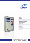
ICON
16
installation
manual
power area1 area2 area3 battery fault tamper
1
2
3
4
5
6
7
8
power area1 area2 area3 area4 area5 area6
1
2
3
4
5
6
7
8
9
1
2
3
4
5
6
7
8
9
10
11
12
13
14
15
16
power area1 area2 area3 battery fault tamper
1
Off
0
On
Isolate
Test
Partial
Icon 16, 32 and 48
version 5.42 January 2002
2
3
4
5
6
7
8
INDEX
Page
1.
2.
3.
4.
5.
6.
7.
8.
9.
10.
12.
13.
14.
15.
16.
17.
Item
New features and functions
Short cuts
Read back programmed functions
Inputs.
Outputs.
Indicators on PCB.
Defaulting the panel - Initialisation.
Power up sequence.
Dialling Sequence.
Other features
Control Panel Functions summary.
Communications Functions summary.
Special Functions.
Sections for Areas 1-3 / Functions 31 to 33
Sections for Areas 4-6 / Functions 34 to 36
Keyswitch sections / Function 37.
Exit Time / Function 40.
Entry Time / Function 41.
Siren Time / Function 42.
Manual De-Isolation of 24 hour sections / Function 43.
Dead Man Timer Start Time / Function 44.
Dead Man Timer Stop Time / Function 45.
Dead Man Timer Timeout period / Function 46.
Panic silent or audible / Function 47.
Fridge Alarm Delay / Function 48.
Exit / Entry Sections in ON Mode / Function 49.
Exit / Handover in ON Mode / Function 50.
24 Hour Sections / Function 52.
Enable Expander / Function 53.
Disable Sirens / Function 54.
Silent Sections / Function 55.
Day Silent Sections / Function 56.
Dead Mans Timer Sections / Function 57
Number of Areas / Function 58.
(C) Copyright 2002
MCM Electronics Pty Ltd
INDEX cont'd
Page
18.
19.
20.
21.
22.
23.
24.
25.
26.
27.
28.
29.
30.
31.
32.
34.
Item
Backup account number / Function 59
Account Number / Function 60.
Day Local Sections / Function 61.
Down Loading (Ring Back) Phone Number / Function 62.
Open/Close Reports / Function 63.
Phone Number 1 / Function 64.
Phone Number 2 / Function 65.
Dialling Method / Function 66.
Transmission Format / Function 67.
Report Restorals / Function 68.
Test Reports / Function 69.
Securitel / GSM backup / Function 70
Report Isolated Sections / Function 71.
Report User IDs / Function 72.
Time of Test Report / Function 73.
Keyboard Duress / Function 74.
Multi- Break Sections / Function 76.
Outputs OP1-2 / Function 81 to 82
Output OP3 / Function 83
Chime Sections - Output 4/ Function 84.
Output OP5 / Function 85
Outputs OP6-8 / Function 86-88
Default to Factory / Function 90 use link...
Printer Baud Rate / Function 94
Print Event Log Now / Function 96
Time Set / Function 97
Date Set / Function 98
Technician Code / Function 99
Master Code / Function 00
User Codes / Function 01 - 30
Test Functions
Contact ID Reporting
Securitel Reporting
Downloading
Version Control
(C) Copyright 2002
MCM Electronics Pty Ltd
New features and functions
Chime Mode
Any selected section can cause output 4 to give a pulse output to drive a
sonalert or screamer when that section is unsealed. Setup by function 84.
Keyswitch operation
Select up to six sections (from sections 11-16) to arm or disarm (and
panic) by a momentary or latching trigger of the section.
Separate combinations of areas can be selected to be controlled by each
keyswitch input and the opening and closings report via users 81-86.
Securitel Line Fail
Backup to Dialler or GSM
Function 59 (backup account number) and Function 70 (Delay to backup)
added to enable line fault detection on STU line to cause the reporting to
use an alternate format. CID via dialler / GSM.
Tape or Domestic
Tape dial allows the panel to report to a standard phone or mobile.
Upload / DownLoad
Allows remote programming via modem and retrieval of history
(up to 2000 events)
Short Cuts
Here are some related functions which may help in programming the Panel
Keypad
Codes
Functions
Functions
Time Functions
Section Setup
Area Setup
Dialler
Down load
Securitel
Dead Man Timer
Printer
Special Functions
Keyswitch Functions
Chime sections
Functions
Functions
Functions
Functions
Functions
Functions
Functions
Functions
Functions
Functions
Functions
54, 58, 74
00- 30 and 99 with Tech Code
00- 80 with Master Code
40, 41, 42, 73, 97, 98
49, 50, 52, 53, 55, 56, 57, 61, 75
31, 32, 33, 34, 35, 36, 58
60, 61, 63, 66, 67, 69, 71, 72, 73, 74, 76
60, 62, 66
60, 61, 63, 67, 71, 72, 74, 76
44, 45, 46, 57
94, 96
54, 58, 74, 81-88
37, 81-86 (delete sections used from 31-36)
84 - output on OP4
Notes
1.
Day Local Sections - only generate local sirens, bells and strobes when
in Day Mode (i.e. the area is disarmed).
2.
Open / Close Reports can be enabled / disabled for each area 1-6.
Individual area reporting may not be required if Full system Close and Open is required.
Area 7 can be separately selected to report first to open, last to close messages.
3.
When programming user code areas or privileges:
Area 9 is used to allow the user access to the test functions.
Area 10 is used to allow the user to isolate sections.
4.
User Codes 81-86 are reserved as keyswitch users for inputs 11-16 see function 37
5.
To enter program or test modes, all areas must be in the off mode.
Page 1
(C) Copyright 2002
MCM Electronics Pty Ltd
Readback
Notes
1.
For functions 31-36,49,50,52,55,56 and any others relating to sections, when the
function number is entered, previously selected sections will flash. If at this point
the Code or On button is pressed no changes will be made and the power LED will be
flashing again and you can select the next Function.
To de-select a section when the sections are displayed, re-enter that sections number,
The section LED will be off.
2.
For all other function numbers, whilst in PROGRAM mode, if an option is entered
followed by the TEST key then that options setting will be read back using the LEDs on the
programmer as follows.
LED
Indicated Digit
1
1
2
2
3
3
4
4
5
5
6
6
7
7
8
8
9
9
10
0
If you wish to check Function 60 ( Account number), enter the 6 0 followed by the TEST key.
( In this case option 60 is 0199 )
(digit 0) Section 10 LED will light accompanied by a beep
(digit 1) Section 1 LED will light accompanied by a beep
(digit 9) Section 9 LED will light accompanied by a beep
(digit 9) Section 9 LED still lit and accompanied by a beep
Then beep-beep and the POWER led flashing again (Test completed ready for next function)
Inputs
All Inputs
Are 10K end of line monitored, with a response time of approximately 300-500ms.
Alarm triggers Siren, Strobe, Outputs and Reporting. (depending on setup)
Inputs 1-48
These inputs may be partitioned into any of the six areas.
For more on partitioning see description of Partitioning below.
May be programmed to have EXIT / ENTRY or EXIT / HANDOVER delays,
and may be programmed for 24 HOUR, SILENT or DAY SILENT operation. These
inputs when in alarm can be programmed to operate outputs 1-3 (see function 81-83)
Fridge
Section 24 may be programmed as a Fridge alarm (Timed 24 hour).
The Fridge input is ignored unless unsealed for a period of time set by Function 48.
16VAC
These terminals are for connection to a 16 -18vac 1.5 amp plug pack.
Partitioning
Chime
The 1-48 inputs may be grouped into six areas. Each Area may be armed and
disarmed independently. Each Area uses an independent entry/exit timer.
Due to noise restriction laws, the siren timer is controlled by all areas, such that the
siren will sound for the preprogrammed time when a non silent section is alarmed.
While the siren timer is running any new section alarms are ignored and do not
cause the siren time to increase. Any user code may be used to turn the sirens off.
If a section is in more than one Area or Partition then the section is armed when
all its Partitions are armed
Any section can be programmed for a chime using function 84 (chime output is OP4)
Keyswitch
Sections 11-16 can be programmed as a Keyswitch input using function 37.
(C) Copyright 2002
MCM Electronics Pty Ltd
Page 2
Outputs
OP1:
This Open Collector output is activated when any of the preprogrammed
sections (Function 81) are in the alarm condition. Output via 100 Ohm resistor.
OP2:
This Open Collector output is activated when any of the preprogrammed
sections (Function 82) are in alarm. Output via 100 Ohm resistor.
OP3:
This Open Collector output is activated when any of the preprogrammed
sections (Function 83) are in alarm Output via 100 Ohm resistor.
OP4:
This Open Collector output is activated when any of the preprogrammed
sections are unsealed (see Function 84). Double pulse output for CHIME.
Output via 100 Ohm resistor, connect a sonalert between OP4
and +12 volts for CHIME.
OP5:
This Open Collector output is activated when the panel is in TEST mode or
Dead Mans Timer (DMT) is running. See Function 46 to enable DMT.
OP6:
This Open Collector output is activated when any of the preprogrammed
sections are Isolated. Programmed with (Function 86) or Dead Mans Warning/Alarm.
OP7:
This Open Collector output is activated when ANY of the preprogrammed areas
are in the On mode. Programmed with (Function 87).
OP8:
This Open Collector output is activated when ALL of the preprogrammed areas
are in the On mode. Programmed with (Function 88).
RS232 PRINT T
RS-232 printer output. Baud rate programmed with option 94 (Default 9600,8,1,0).
RS232 PRINT -
Printer signal ground.
Aux 12:
12VDC outputs for detectors, etc. The outputs are via the INTERNAL fuse.
Between 200 - 500mA can be delivered to load depending on siren, strobe.
The onboard regulation is rated at 1.5amps and of this, the battery can take up to
200mA depending on the state of charge. One strobe requires 250mA and each
speaker 200mA. The panel itself in alarm with one keypad draws 150mA approx.
Batt:
This output is connected to the onboard regulator via a resistor which limits
the charge current. Charging voltage is 13.7V.
+Int:
This terminal is +12VDC fused via the INTERNAL fuse, connects to Internal
Bell/Screamer, Internal Siren, Keypad and Detectors.
+Ext:
This terminal is +12VDC fused via the EXTERNAL fuse, connects to External Siren
and Strobe.
Int Sir:
Timed output to drive 1 x 8 ohm speaker rated at 10 watts, fused via INTERNAL fuse.
Int Bel:
Timed output to drive DC screamers, fused via INTERNAL fuse.
Ext Stb:
12vdc untimed output to drive 12vdc strobe, fused via EXTERNAL fuse.
Ext Sir:
Timed output to drive 1 x 8ohm speaker rated at 10 watts, fused via EXTERNAL fuse.
Telecom
Connector :
This is where the Telecom lead, which is supplied with the unit is connected.
The Telecom lead uses pins 2 & 6 of the Telecom socket for the incoming line
and pins 1 & 5 connect to the telephone in a MODE 3 arrangement.
Page 3
(C) Copyright 2002
MCM Electronics Pty Ltd
Outputs cont’d
High
Integrity
Earth:
This terminal connects to a dual GAS ARRESTOR. This device is the same as
used by Telecom in exchanges and main frames to protect against lightning induced voltages.
If this terminal is connected to an earth rod or cold water pipe, the tolerance to
high voltage or lightning induced transients is greatly increased. The Telecom input
normally has a high tolerance to transients but with this terminal connected the
tolerance is even greater. Use a heavy conductor for this purpose 40/020 or similar.
R0 T0
These 2 terminals together with the + and - terminals are used to connect to an
RS232 STU (R0 connects to Tx on the STU and T0 connects to Rx on the STU).
+ - C D1: These 4 terminals connect to the keypads that display sections 1 up to 24.
D2:
This terminal connects to the keypad when required to display sections 25 - 48.
The terminal marked + connects to the terminal marked + on the keypad
The terminal marked CLK connects to the one marked C on the keypad
The terminal marked D1 and D2 connect to D1 and D2 on the keypad
The terminal marked - connects to the terminal marked - on the keypad
Leds on the PCB
Scan:
This green led near the keypad screw terminals indicates that the micro-processor
is operating and must always be flickering.
Sir:
This red LED is near the fuses and indicates when the siren is running.
Stb:
This red LED is near the fuses and indicates when the strobe output is on.
Dial:
This red LED is near the Line Sieze relay and indicates when the Dialler is on line.
Rx:
This yellow LED is near the Rx2 screw terminal and will flicker when RS232 data is
being received on the Rx2 screw terminal.
Tx:
This red LED is near the Tx2 screw terminal and will flicker when the panel is
transmitting RS232 data on the Tx2 screw terminal.
MCD:
This green LED is near the telecom transformer and illuminates when the onboard
modem is detecting a carrier.
MRX:
This yellow LED is near the telecom transformer and flickers when the modem is
receiving serial data or Rx0 is receiving data from a reporting device.
MTX:
This red LED is near the telecom transformer and flickers when the panel is
transmitting data to the onboard modem or Tx0 to a reporting device.
OP1:
OP2:
OP3:
OP4:
OP5:
OP6:
OP7:
OP8:
This LED is on when the output OP1 setup by function 81 is on or active low.
This LED is on when the output OP2 setup by function 82 is on or active low.
This LED is on when the output OP3 setup by function 83 is on or active low.
This LED is on when the output OP4 setup by function 84 is on or active low.
This LED is on when the output OP5 setup by function 85 is on or active low.
This LED is on when the output OP6 setup by function 86 is on or active low.
This LED is on when the output OP7 setup by function 87 is on or active low.
This LED is on when the output OP8 setup by function 88 is on or active low.
(C) Copyright 2002
MCM Electronics Pty Ltd
Page 4
Defaulting the Panel
To initialize the panel to factory defaults, momentarily link/short the Default pins on power up for 3
seconds. While the panel is defaulting, the area leds will scan from left to right.
These pins are located near the large square chip in the centre of the PCB. This will default all system setup
values and user numbers etc, back to known default values.
On Power Up
On power up the unit performs an internal self test of Non Volitile Memory. If the Non Volitile memory is
found to have been corrupted in some way then the factory defaults will be reloaded. On power up the unit
starts off in the OFF mode and the sirens may operate for half a second.
Dialling Sequence
The dialling sequence from start to finish consists of 6 dialling attempts as follows:
3 dialling attempts to the phone number 1 ( setup in Function 64),
The dialler will release the line for 5 minutes,
Then dial 3 more attempts using number 2 ( setup in Function 64)
(if no second number has been programmed then the first number will be tried again).
If after these attempts handshake is still not received, dialling will cease until another condition causes it to
dial, at which time the previous condition will also be reported.
Other Features
Keyboard Duress:
Mains Fail:
Low Battery:
Page 5
Duress is sent by entering your normal 4 digit code but with the last digit
incremented by 1.
If your code is “ 1234 “ then enter “1235 “ a duress alarm is sent with no
local alarm.
A duress restore is sent when the next valid code is entered. If the last digit of
your code is “ 0 “ then enter a “ 1 “. Or if a 9 enter a 0.
Mains fail is detected automatically by the panel.
When mains fail is detected the power LED on the keypad will give a single
flash and keypad will be beeping. The beeper will stop when any button is
pressed. After mains failure has occurred for more than 60 minutes the panel
will report a mains fail alarm. When mains is restored the power LED will go
steady again and after 10 seconds the panel will report a mains restoral.
Low battery is detected automatically by the panel. When low voltage is detected
the power LED on the keypad will give a double flash. After the system voltage has
been low for 60 seconds the panel will report the Low Battery. When the system
voltage is restored to normal, the power LED will go steady and after 10 seconds
the panel will report a low voltage restoral.
(C) Copyright 2002
MCM Electronics Pty Ltd
Control Panel Function List
Function
Num of Digits
6
4
4
Defaults
00
01
02
Master Code holder
User code 1 (Areas: All)
and up to 86 User code (Areas: All)
218572
1111
Nil
***
User codes 01-30 programmed with Tech code, 01-80 with Master Code ***
User codes 81- 86 are used to set up Areas assigned to keyswitch sectios 11-16
31
32
33
34
35
36
37
Area 1 Sections
Area 2 Sections
Area 3 Sections
Area 4 Sections
Area 5 Sections
Area 6 Sections
Keyswitch Sections
2
2
2
2
2
2
2
1 to 48
Nil
Nil
Nil
Nil
Nil
Nil
40
41
42
43
44
45
46
47
48
49
50
52
53
54
55
56
57
58
Exit time
Entry time
Siren time
Manual De - Isolate of 24 hour sections
Dead Mans Timer ..Start Time
Dead Mans Timer ..Stop Time
Dead Mans Timer ..Timeout Period
Panic silent or audible (Not Used)
Fridge Alarm Delay (Section 24) ++
Exit and Entry sections
Exit and Handover sections
24 hour inputs
Number of 16 input Expanders connected
Disable sirens on first keypress
Silent Sections
Day Silent Sections +++
Dead mans Timer Sections
Number of Areas
1
1
1
1
4
4
1
1
1
2
2
2
1
1
2
2
2
1
60 secs
30 secs
5 min
Enabled
0000
0000
Disabled
Audible
Disabled
1+2
Nil
Nil
Nil
No
Nil
Nil
Nil
6
Note:
When programming user code areas:
LEDs 1-6 are areas 1-6. LEDs 7 and 8 are spare.
LED 9 is not a physical area but is used to allow access to the test functions.
LED10 is not a physical area but is used to allow users to isolate sections.
++
When the Fridge Delay is enabled Section 24 becomes a Fridge Input.
+++When an area is not armed the area is in Day Mode, a section programmed for that
area is in Day Mode.
(C) Copyright 2002
MCM Electronics Pty Ltd
Page 6
Communications Functions
60
61
62
63
64
65
66
67
68
69
70
71
72
73
74
76
Function
Account number
Day Locals +
DownLoading (Ring Back) Phone No
Area Open / Close reports ++
Phone Number one
Phone Number two
Dial method
Transmission Format
Report Restorals
No of days between test reports
Securitel Backup Timeout
Report Isolates
Report User IDs
Time of test report
Keyboard Duress
Multi-Break
# of Digits
4
2
15 max
2
15
max
15
max
1
1
1
1
1
1
1
4
1
2
Defaults
0000
Nil
Nil
Areas 1-7
Nil
Nil
Tone
Contact ID
Yes
0
30secs
Yes
Yes
Disabled,0000
Disabled
Nil
Special Functions
81
82
83
84
85
86
87
88
90
94
96
97
98
99
Function
Output OP 1 Sections
Output OP 2 Sections
Output OP 3 Sections
Output OP 4 Sections
Output OP 5
Output OP 6
Output OP 7 Areas
Output OP 8 Areas
Default to factory (see also Initialization)
Printer Baud Rate
Print Event Log - (as it happens)
Time Set
Date Set
Technician Code
# of Digits
2
2
2
2
2
2
2
2
0
1
1
4
6
6
+
Day Local Sections only generate local sirens, bells and strobes when
in Day Mode (i.e. the area is disarmed).
++
Open / Close Reports can be enabled / disabled for each area 1-6.
Individual area reporting may not be required if Full system Close and
Open is required (Area 7).
Area 7 can be separately selected to report first to open, last to close messages.
Page 7
(C) Copyright 2002
Defaults
Nil
Nil
Nil
Nil
Nil
Nil
Nil
Nil
N/A
9600,8,1,N
No, on request
0900
010999
218067
MCM Electronics Pty Ltd
Function 31 Area 1 sections -
Default Sections 1-48
Display and change which sections will operate as Area 1 inputs.
Key Sequence
2 1 8 0 6
3 1
7 On
0 1
0 2
0 3
On
Off
Operation
Enter Tech code( default 218067 )
Select Function 31
(previously selected sections will flash)
Section 1 is in area 1
Section 2 is in area 1
Section 3 is in area 1
Store this selection
Exit program mode
Function 32 Area 2 sections -
Default Sections Nil
Display and change which sections will operate as Area 2 inputs.
Key Sequence
2 1 8 0 6
3 2
7
On
0 9
1 0
1 1
On
Off
Operation
Enter Tech code( default 218067 )
Select Function 32
(previously selected sections will flash)
Section 9 is in area 2
Section 10 is in area 2
Section 11 is in area 2
Store this selection
Exit program mode
Function 33 Area 3 sections -
Default Sections Nil
Display and change which sections will operate as Area 3 inputs.
Key Sequence
2 1 8 0 6
3 3
7
On
1 7
1 8
1 9
On
Off
(C) Copyright 2002
MCM Electronics Pty Ltd
Operation
Enter Tech code( default 218067 )
Select Function 33
(previously selected sections will flash)
Section 17 is in area 3
Section 18 is in area 3
Section 19 is in area 3
Store this selection
Exit program mode
Page 8
Function 34 Area 4 sections -
Default Sections Nil
Display and change which sections will operate as Area 4 inputs.
Key Sequence
2 1 8 0 6
3 4
Operation
Enter Tech code( default 218067 )
Select Function 34
(previously selected sections will flash)
2 7
Section 27 is in area 4
On
Store this selection
Select another function number or Exit program mode using the OFF key
7
On
Function 35 Area 5 sections -
Default Sections Nil
Display and change which sections will operate as Area 5 inputs.
Key Sequence
2 1 8 0 6
3 5
Operation
Enter Tech code( default 218067 )
Select Function 35
(previously selected sections will flash)
0 1
Section 1 is in area 5
0 2
Section 2 is in area 5
0 3
Section 3 is in area 5
On
Store this selection
Select another function number or Exit program mode using the OFF key
7 On
Function 36 Area 6 sections -
Default Sections Nil
Display and change which sections will operate as Area 6 inputs.
Key Sequence
2 1 8 0 6
3 6
Operation
Enter Tech code( default 218067 )
Select Function 36
(previously selected sections will flash)
0 9
Section 9 is in area 6
1 0
Section 10 is in area 6
On
Store this selection
Select another function number or Exit program mode using the OFF key
Page 9
7
On
(C) Copyright 2002
MCM Electronics Pty Ltd
Function 37 Keyswitch sections -
Default Sections Nil
This function provides the keyswitch functionality to the ICON 16 allowing a remote arming facility, based
on the change in state of one or more (up to 6) keyswitch sections (sections 11-16). The keyswitch can be
used to arm or disarm an area or a group of areas, depending on the “Areas” setup of the current keyswitch
User (Users 81 to 86).
It can also create a panic alarm if activated for more than 3 seconds
Programming Options needed to be setup:
User 81-86
=
User 81keyswitch areas and chirp outputs.
Note this must be setup with a Master code not the Tech code.
Function 37
=
Keyswitch Sections 11 to 16
Function 31
=
Remove sections in areas when used as keyswitch sections
Keyswitch Sections - Function 37
Display and change which sections will operate as keyswitch inputs.
Only sections 11-16 can be keyswitch sections, and the Areas that are controlled by each keyswitch input
are assigned by programming User Codes 81-86 with the Master Code
(input/section 11 setup by user 81, input 12 setup by user 82 etc.)
Note: Make sure you remove keyswitch sections out of Function 31-36.
Key Sequence
2 1 8 0 6
3 7
Operation
Enter Tech code( default 218067 )
Select Function 37
(previously selected sections will flash)
1 1
Section 11 when flashing is a keyswitch input
1 2
Section 12 when flashing is a keyswitch input
On
Store this selection
Select another function number or Exit program mode using the OFF key
7
On
Whilst it is not necessary to setup every keyswitch user, or any in fact, the unused users cannot be setup as
general users.
Continued on next page.....
(C) Copyright 2002
MCM Electronics Pty Ltd
Page 10
Function 37 Keyswitch sections
Cont’d
User Setup (Areas):
1-6
Area Control - Arming/Disarming of areas, as a normal user setup.
Default areas 1- 6
7
Acknowledge Alarms only (Mute) - Default enabled
8
Reset and Mute - Default enabled
9
Enable Panic - Default disabled
10
Chirp the Bell Output - Default enabled
11
Chirp the Siren Output - Default enabled
12
Flash the Strobe Output - Default enabled
13
Momentary or Latching - Default Momentary
If latching is used, then the panic option is not available.
Beep / Chirp / Flash:
Arming
300m/S On
300m/S Off
300m/S On
Disarming
600m/S On
Error
300m/S On
300m/S Off five times
(Unsealed sections inhibiting arming)
Note:
A change has been made to the normal operation via keypad. If any of the selected areas have unsealed
sections, then NO AREA will arm.
A keyswitch section cannot be part of an area. If it is included in an area, it may be ignored within that area
while it is setup as a keyswitch section.
Where there are multiple keyswitch areas, and an arm request is received, if any of the keyswitch areas
have an unsealed section, NO AREA will arm.
The priority will be to turn off areas, this means that when a keyswitch input is activated, if any keyswitch
areas are armed at that time, then these areas will be disarmed. The following activation of the keyswitch
input will then arm all the keyswitch areas.
User 81-86 will be used for reporting and logging keyswitch operations
The Keyswitch Users, 81-86 are dedicated, and cannot be setup as panel users if they or any of them are
not used as Keyswitch.
Only sections 11-16 can be setup as Keyswitch Sections, however, in this case, if any, or all of these
sections is not to be used as a Keyswitch Section, then that section can be programmed in general use.
Page 11
(C) Copyright 2002
MCM Electronics Pty Ltd
Function 40 Exit Time
Options
0 0 seconds
1 10 seconds
2 20 seconds
3 30 seconds
4 40 seconds
Key Sequence
2 1 8 0 6
4 0
5 On
5
6
7
8
9
7
-
Default 60 seconds
50 seconds
60 seconds
70 seconds
80 seconds
90 seconds
Operation
Enter valid Technician code ( default 218067 )
Select function number 40
Select & store option number ( example
shows option 5, i.e. 50 secs being selected ).
Exit Program mode
On
Off
Function 41 Entry Time
Options
0 0 seconds
1 10 seconds
2 20 seconds
3 30 seconds
4 40 seconds
Key Sequence
2 1 8 0 6
4 1
3 On
5
6
7
8
9
7
-
Default 30 seconds
50 seconds
60 seconds
70 seconds
80 seconds
90 seconds
Operation
Enter valid Technician code (default 218067 )
Select function number 41
Select & store option number ( example
shows option 3, i.e. 30 secs being selected ).
Exit Program mode
On
Off
Function 42 Siren Time
Options
0 0 seconds
1 10 seconds
2 20 seconds
3 40 seconds
4 80 seconds
Notes:
5
6
7
8
9
-
Default 5 minutes
2 min 40 sec
5 min
10 min
21 min
42 min
Siren time applies to internal, external and satellite sirens. Australian
Standards AS 2201 limit siren to be triggered only once per section unless
manually re-set. Noise pollution regulations in most states limit siren time
to 5 minutes.
Key Sequence
2 1 8 0 6
4 2
5 On
Off
(C) Copyright 2002
7
On
MCM Electronics Pty Ltd
Operation
Enter valid Technician code (Default 218067)
Select function number 42
Select & store number e.g. 5 = 160 seconds is selected
Exit Program mode
Page 12
Function 43 Manual De-Isolate
Options
1 - Enabled.
0 - Disabled.
Default Enabled
24 hour sections will remain isolated when disarming.
24 hour sections will automatically de-Isolate when disarming.
Key Sequence
2 1 8 0 6
4 3
1 On
Off
7
On
Operation
Enter valid Technician code (Default 218067)
Select function number 43
Select & store option number e.g. 1 = Enable
Exit Program mode
Function 44 Deadman Timer - Start
Default Nil
This Function is used to set the Start time of the Dead Mans timer See also function 45 and 46
Format is HHMM
where: - HH is hours in range 00 - 23,
MM is minutes in range 00 -59
Key Sequence
2 1 8 0 6 7 On
4 4
0 9 3 0
On
Off
Operation
Enter existing Tech code ( default is 218067 )
Select function 44
Set the Start Time to 9.30 am.
Exit Program mode
Function 45 Deadman Timer - Stop
Default Nil
This Function is used to set the Stop time of the Dead Mans timer See also function 44 and 46
Format is HHMM
where: - HH is hours in range 00 - 23,
MM is minutes in range 00 - 59
Key Sequence
2 1 8 0 6 7 On
4 5
2 3 3 0
On
Off
Page 13
Operation
Enter existing Tech code ( default is 218067 )
Select function 45
Set the Stop Time to 11:30 pm
Exit Program mode
(C) Copyright 2002
MCM Electronics Pty Ltd
Function 46 Deadman Timer - Timeout
Default 0
Note:
The Deadmans Timer Function is setup by functions 44, 45, 46 and 57. During the Start / Stop period
Function 46 is used to set the maximum time during which the "Deadmans Timer Sections " as set by
Deadmans Timer "Alarm" is reported as Section 255 Alarm
Options
0 Disabled
1 15 Minutes
2 30 Minutes
3 45 Minutes
4 60 Minutes
Key Sequence
2 1 8 0 6
4 6
4 On
Off
5
6
7
8
9
7
On
-
75 Minutes
90 Minutes
105 Minutes
120 Minutes
135 Minutes
Operation
Enter valid Technician code
Select Function 46
Set timeout to 60 minutes.
Exit program mode
Function 47 Silent / Audible Panic
Default Audible
Option
1
Audible Panic
0
Silent Panic ( no strobe or siren )
Note:
This option is for the Key board Panic only
Key Sequence
2 1 8 0 6
4 7
0 On
7 On
Off
Operation
Enter Tech code (default 218067)
Select Function 47
Select option 0 or 1
Example shows option 0 selected
which is silent panic
Exit program mode
Function 48 Fridge Alarm Delay
Options
0 Fridge input disabled
1 15 minutes
2 30 minutes
3 45 minutes
4 1 hour
5
6
7
8
9
-
Default Disabled
1 hour 15 minutes
1 hour 30 minutes
1 hour 45 minutes
2 hours
Fridge input disabled
Note:
When an option other than 0 or 9 is selected, input 24 becomes a Fridge input.
Key Sequence
2 1 8 0 6
4 8
2 On
Off
(C) Copyright 2002
7
On
Operation
Enter Tech code (default 218067)
Select Function 48
A delay of 30 minutes selected
Exit program mode
MCM Electronics Pty Ltd
Page 14
Function 49 Exit Entry Sections
Default 1,2
Display and change which sections will have exit / entry delay.
Key Sequence
2 1 8 0 6
4 9
7
On
0 2
0 8
On
Off
Operation
Enter Tech code (default 218067)
Select Function 49
(any previously selected sections will flash)
Section 2 has exit / entry delay
Section 8 has exit / entry delay
Store this selection
Exit program mode
Function 50 Exit Handover Sections
Default Nil
Display and change which sections will have exit / handover delay. Handover is enabled when any section
that has been programmed for Exit / Entry delay has been activated first.
Key Sequence
2 1 8 0 6
5 0
7
On
0 2
0 8
On
Off
Operation
Enter Tech code (default 218067)
Select Function 50
(any previously selected sections will flash)
Section 2 has exit / handover
Section 8 has exit / handover
Store this selection
Exit program mode
Function 52 24Hr Sections
Default Nil
Display and change which sections will operate as 24 hour inputs.
Key Sequence
2 1 8 0 6
52
06
07
23
24
On
Off
Page 15
7
On
Operation
Enter Tech code (default 218067)
Select Function 52
(any previously selected sections will flash)
Section 6 is a 24 hour input
Section 7 is a 24 hour input
Section 23 is a 24 hour input
Section 24 is a 24 hour input
Store this selection
Exit program mode
(C) Copyright 2002
MCM Electronics Pty Ltd
Function 53 Number of Expanders
Default Nil
Option
0
No expander fitted
1
1 expander fitted
2
2 expanders fitted
When expanders are fitted, a jumper on the expander board configures the input numbering.
Group 1 i.e. Sections 17 - 32 or
Group 2 i.e. Sections 33 - 48
Key Sequence
2 1 8 0 6
5 3
2 On
7
On
Off
Operation
Enter Tech code (default 218067)
Select Function 53
Select 2 expanders (Sections 17-32 and 33-48)
Example shows 2 selected
Exit program mode
Function 54 Disable Sirens on first Keypress
Default - Do not disable
Option
1
Disable sirens on first keypress
0
Do not disable sirens
Note:
If the function enabled and if the sirens are operating when the first number in a code is entered,
the sirens will be shut off for 10 seconds after which they will turn on again unless a valid user
code is used to acknowledge the alarm. This can only happen once during an Armed or
Disarmed period.
Key Sequence
2 1 8 0 6
5 4
1 On
Off
7
On
Operation
Enter Tech code (default 218067)
Select Function 54
Select 1 Disable Siren on first keypress
Exit program mode
Function 55 Silent Sections
Default Nil
Display and change which sections will operate as silent sections. i.e. No Siren and Strobe.
Key Sequence
2 1 8 0 6
55
06
24
On
Off
(C) Copyright 2002
7
On
Operation
Enter Tech code (default 218067)
Select Function 55
(previously selected sections will flash)
Section 6 is a silent input
Section 24 is a silent input
Store this selection
Exit program mode
MCM Electronics Pty Ltd
Page 16
Function 56 Silent Sections in Day Mode
Default Nil
Display and change which sections will operate as silent sections in Day mode.
Day Mode is when the area is disarmed in which the sections are programmed.
Silent means both Siren and Strobe will not be activated
Outputs OP1 - 3 can be used to give local alarm outputs.
Day Local sections (alarms on these sections will not report to Central Station in Day Mode) can be
programmed by option 61.
Key Sequence
2 1 8 0 6
56
7
On
06
07
On
Off
Operation
Enter Tech code (default 218067)
Select Function 56.
(previously selected sections will flash)
Section 6 is a day silent input.
Section 7 is a day silent input.
Store this selection.
Exit program mode.
Function 57 Deadman’s Sections
Default Nil
Display and change the Sections that will reset the Dead Man Timer (DMT) during the DMT
time period as set up by functions 44, 45, 46.
Key Sequence
2 1 8 0 6
57
04
On
Off
7
On
Operation
Enter Tech code (default 218067)
Select Function 57.
Section 4 selected to reset DMT.
Store this selection.
Exit program mode.
Function 58 Number of Areas
Default 6
Display and change the number of Areas that exist in the panel (1-6)
Options
1
2
3
-
1 Area
2 Areas (1 and 2)
3 Areas (1, 2 and 3)
Key Sequence
2 1 8 0 6
58
4
On
Off
Page 17
7
On
4
5
6
-
4 Areas (1, 2, 3 and 4)
5 Areas (1, 2, 3, 4 and 5)
6 Areas (1-6)
Operation
Enter Tech code (default 218067)
Select Function 58.
Panel selected to have 4 Areas.
Store this selection.
Exit program mode.
(C) Copyright 2002
MCM Electronics Pty Ltd
Function 59 Backup Account Number
Default Nil
Notes:
1.
See function 70 for details of Securitel line fail backup to GSM or dialler
2.
4 Digits Limits 0000- 9999
3.
This backup account number is used only when programmed for Securitel (Function 67=9)
and line fail detection is enabled with a Line Fault Monitor and connected into section 16
and programmed as per function 70
Key Sequence
2 1 8 0 6 7
5 9
6 6 6 6 On
Off
On
Operation
Enter valid Technician code.
Select function 59
Enter Backup Account number - example 6666
Exit Program mode
Function 60 Account Number / HID
Notes:
1.
2.
3.
4.
5.
Default Nil
4 Digits Limits 0000- 9999
This function is used to enter the account number for transmission to the Central Station.
The dialler will not dial if account number or phone number not programmed.
When Option 67 is set to 3 then area 1 uses this Account Number , area 2 uses Account
Number +1, area 3 uses Account Number +2, area 4 uses Account Number +3 etc.
This Account number is the Hard I.D. when programmed for Securitel (Function 67=9)
Key Sequence
2 1 8 0 6 7
6 0
6 6 6 6 On
Off
On
Operation
Enter valid Technician code.
Select function 60
Enter Account number - example 6666
Exit Program mode
Function 61 Day Local Sections
Default Nil
Display and change which sections will operate as local sections. In Day mode these sections will not
report an alarm back to the Central Station. Sirens, Strobe and outputs 1-3, depending on options
55,56,81,82,83.
Day Mode is when the area is disarmed.
Key Sequence
2 1 8 0 6
6 1
7
On
06
On
Off
Operation
Enter Tech code (default 218067)
Select Function 61
(previously selected sections will flash)
Section 6 is selected for day local
Store this selection
Exit program mode
Function 62 Download Phone number
Default Nil
Note:
The phone number may be up to 15 digits long Including pauses
1 sec pause = Partial key.
Key Sequence
2 1 8 0 6 7
6 2
047 Partial 218067
On
Off
(C) Copyright 2002
On
MCM Electronics Pty Ltd
Operation
Enter valid Technician code (default 218067 ).
Select function 62
e.g. shows 047 pause 218067
Store Entry
Exit Program mode
Page 18
Function 63 Open / Close Reports
Default Areas 1-7
This function is used to select which areas will send open and close reports.
Note:
1.
Option 7 or Area 7 is not an area but is used to select first to open / last to close reporting.
2.
Open / Close Reports can be enabled / disabled for each area 1-6.
3.
Individual area reporting may not be required if Full system Close and
Open is required (Area 7).
Key Sequence
2 1 8 0 6
6 3
0 5
On
Off
7
On
Operation
Enter valid Technician code ( default 218067 )
Select function 63 (previous selections will flash)
Area 5, if flashing, will report open and close messages
Store entry
Exit Program mode
Function 64 Phone number 1
Default none
Note:
The phone number may be up to 15 digits long including pauses.
1 sec pause = Partial key.
Key Sequence
2 1 8 0 6 7
6 4
047 Partial 218067
On
Off
On
Operation
Enter valid Technician code ( default 218067 )
Select function 64
e.g. shows 047 pause 218067
Store Entry
Exit Program mode
Function 65 Phone number 2
Default none
Note:
The phone number may be up to 15 digits long including pauses.
1 sec pause = Partial key.
Key sequence
2 1 8 0 6
6 5
047218572
On
Off
Page 19
7 On
Operation
Enter valid Technician code( default 218067 )
Select function 65
e.g. shows 047218572
Store entry
Exit Program mode
(C) Copyright 2002
MCM Electronics Pty Ltd
Function 66 Dialling method
Default DTMF(tone)
Selects to dial in DTMF (Tone) or Decadic Dialling
Option
1
Dial in DTMF, (tone)
0
Dial in Decadic, (pulse)
2
Dial in New Zealand Decadic (Pulse)
Key Sequence
2 1 8 0 6
6 6
1
On
Off
7
On
Operation
Enter valid Technician code ( default 218067 )
Select function 66
Dial in DTMF
Store entry
Exit Program mode
Function 67 Transmission Format
Default Contact ID
Option
0, 2, 3 Dialling Disabled
1
Tape Dial (only with Version 4.5 software and above)
4
Contact ID Single Account Number multiple Areas or Partitions
5
EDL Direct Line, set account number, Function 60 - Special PCB marked "Direct Line"
9
Securitel via RS232 STU Connected to T0, R0, + and - terminals. Set HID with option 60.
Key Sequence
2 1 8 0 6
6 7
4
On
Off
7
On
Operation
Enter valid Technician code ( default 218067 )
Select function
Contact ID Format Selected
Store entry
Exit Program mode
Function 68 Report Restorals
Default Report Restorals
The dialler will normally report when an input is restored to a non alarm condition.
This is usually when the panel is disarmed.
Option
1
Report restorals
0
Do not report restorals
Key sequence
2 1 8 0 6
6 8
0
On
Off
(C) Copyright 2002
7
On
Operation
Enter valid Technician code( default 218067 )
Select function
Don’t report restorals
Store entry
Exit Program mode
MCM Electronics Pty Ltd
Page 20
Function 69 Test Reports
Default 0, no test reports
This function programs the number of days between test reports ( 0 - 9 ),
programming a 0 gives no test reports. Also setup Function 73 Time of Test report.
Options
0
1
2
3
4
-
Test Reports disabled
send test report every day
send test report every 2 days
send test report every 3 days
send test report every 4 days
Key sequence
2 1 8 0 6
6 9
7
On
Off
7
On
5
6
7
8
9
-
send test report every 5 days
send test report every 6 days
send test report every 7 days
send test report every 8 days
send test report every 9 days
Operation
Enter valid Technician code( default 218067 )
Select function
Select period in days (1 - 9) e.g. shows once a week
Store entry.
Exit Program mode
Function 70 Securitel /GSM Backup
Default 0
Overview
This new function has been added to allow the panel to report via Securitel (using an RS232 STU) and in
the event of a Securitel line failure (cut line sensed by a line fail module). The panel will automatically
report the line failure via dialler on GSM or standard PSTN line and keep transmitting any further events via
this backup reporting method until the line fail module has determined the line has restored to normal.
A line fail module is connected on the Securitel line and the output is connected to section 16. When
section16 is faulted and after a delay set by function 70, the panel will go into “Backup mode”. The panel then
uses the “Backup client number” stored in function 59 (or 60 if function 59 is not set). The panel sends a
“section 16 alarm” message (panel operating on backup) to the Central station via the GSM /dialler. The delay
before line fail is reported can be set between 0 and 10 minutes from the detected line fail.
The Line fault detector module has also an inbuilt 30 -second delay.
When the voltage on the Securitel line restores to normal, the line fail module will restore section 16 after a
delay set by function 70. A “section 16 restored” message will be sent to the Central station via dialler/GSM
prior to reverting to Securitel.
The normal setup for this mode of backup operation is as follows:
Reporting format is setup for Securitel (function 67=9)
Account number (Function 60) An alternate backup account number (Function 59) if different from Function 60.
Section 16 connected to the line fail module (section sealed when line ok)
Delete Section 16 from being in an area
Primary phone number (function 64) setup
Secondary phone number (function 65) setup
Backup Account number (function 59).
Function 70 is used to program the Timeout Period as follows:
Value
0
1
2
3
4
5
6
Page 21
Timeout Period
No Timeout Period
10 Second Timeout Period
20 Second Timeout Period
40 Second Timeout Period
80 Second Timeout Period
5 Minute ( 300 Second ) Timeout Period
10 Minute ( 600 Second ) Timeout Period
( 20 Seconds to Restore )
( 40 Seconds to Restore )
( 80 Seconds to Restore )
( 160 Seconds to Restore )
( 10 Minutes to Restore )
( 20 Minutes to Restore )
(C) Copyright 2002
MCM Electronics Pty Ltd
Function 71 Report Isolated Sections
Default report
The control panel will normally report isolated sections.
Option
1
Report Isolated sections
0
Do not report Isolated sections
Key sequence
2 1 8 0 6
7 1
1
On
Off
7
On
Operation
Enter valid Technician code( default 218067 )
Select function
Report isolated sections
Store entry
Exit Program mode
Function 72 Report User Ids
Default report
Note:
If enabled the control panel will report user Ids.
Option
1
Report user IDs
0
Do not report user IDs (Send as User 30 Only)
Key sequence
2 1 8 0 6
7 2
1
On
Off
7
On
Operation
Enter valid Technician code ( default 218067 )
Select function 72
Report user IDs
Store entry
Exit Program mode
Function 73 Time of Test report
Default nil
Note:
This sets the time of day that a test report will be generated.
Format is HHMM
where: - HH is hours in range 00 - 23, MM is minutes in range 00 -59
Key sequences
2 1 8 0 6
7 3
2 3 3 0
On
Off
(C) Copyright 2002
7
On
MCM Electronics Pty Ltd
Operation
Enter valid Technician code( default 218067 .
Select Function
Test report started at 11.30pm.
Store entry
Exit Program mode
Page 22
Function 74 Keyboard Duresss
Default Disabled
Note:
Keyboard duress may be disabled to prevent accidental duress alarms from private residences.
Duress is achieved by adding 1 to the last digit eg. 1234 becomes 1235, 6789 becomes 6780.
Option
1
Duress reports enabled
0
Duress reports disabled
Key sequence
Operation
2 1 8 0 6 7 Code
Enter valid Technician code( default 218067 )
74
Select Function
1
Duress enabled
On
Store entry
Off
Exit Program mode
Function 76 Multibreak Sections
Default None
Display and change which sections will report input condition changes when armed.
Note:
This option will not give multi triggering of sirens to a section but will give multi reporting.
The section LED will latch on first alarm for that section
Key sequence
2 1 8 0 6
7 6
0 9
On
Off
7
On
Operation
Enter valid Technician code( default 218067 )
Select function 76
Select section 9 for multibreak.
Store entry
Exit Program mode
Function 81 Output OP1 Sections
Default None
Display and change which sections when in alarm will activate Output OP1.
If any of the selected sections goes into alarm then Output OP1 is held active until the alarm
condition has been cleared.
Key sequence
2 1 8 0 6
8 1
0 9
On
Off
7
On
Operation
Enter valid Technician code( default 218067 )
Select function 81
Select section 9 to operate OP1 when in Alarm.
Store entry
Exit Program mode
Function 82 Output OP2 Sections
Default None
Display and change which sections when in alarm will activate OP2 output.
If any of the selected sections goes into alarm then Output OP2 is held active until the alarm
condition has been cleared.
Key sequence
2 1 8 0 6
8 2
1 0
On
Off
Page 23
7
On
Operation
Enter valid Technician code( default 218067 )
Select function 82
Select section 10 to operate OP2 when in Alarm.
Store entry
Exit Program mode
(C) Copyright 2002
MCM Electronics Pty Ltd
Function 83 Output OP3 Sections
Default None
Display and change which sections when in alarm will activate OP3 output.
If any of the selected sections goes into alarm then Output OP3 is held active until the alarm
condition has been cleared.
Key sequence
2 1 8 0 6
8 3
1 0
On
Off
7
On
Operation
Enter valid Technician code( default 218067 )
Select function 83
Select section 10 to operate OP3 when in Alarm.
Store entry
Exit Program mode
Function 84 Chime Sections - OP4
Default None
Display and change which sections when unsealed will give 2 pulses on OP4 output (Chime output).
If any of the selected Chime sections are unsealed then Output OP4 will pulse low twice on the opening of
the door or triggering of the sensor (not the sealing of the section). If one Chime section is left unsealed
further activations of the Chime output can still occur from other Chime sections.
Output 4 (OP4) can be connected to a beeper or the internal Bell - terminal. Connecting the OP4to the
Bell - allows the internal screamer to operate as normal and also give a double chirp on the screamer when
a Chime section is triggered. A switch can also be added in series with the beeper to mute as required.
Key sequence
2 1 8 0 6
8 4
1 0
On
Off
7
On
Operation
Enter valid Technician code( default 218067 )
Select function 84
Select section 10 to operate OP4 when in Alarm.
Store entry
Exit Program mode
Function 85 Output OP5 Test or Deadman
No need to program sections into this function
If Function 46 is set to 0 then the Dead Mans Timer is not Active and OP5 is active
Low (i.e. Zero volts) while the panel is in Test mode.
If Function 46 is set to between 1 and 9 then the Dead Mans Timer is Active
Output OP5 is active (Low) while the Dead Man Timer is running.(Between Start and Stop times)
Function 44 sets the Start time.
Function 45 sets the Stop time.
Function 57 sets the sections that are used to reset the timeout while the Dead Mans Timer
is running.
Note:
Dead-man's Timer alarm is reported as a Section 255 Alarm
(C) Copyright 2002
MCM Electronics Pty Ltd
Page 24
Function 86 Output OP6 sections
Default Nil
Section Isolated
If Function 46 is set to 0 then the Dead Mans Timer is not active and OP6 is active
low (i.e. Zero volts) while a section is isolated and that section is selected in Function 86 .
If any of the selected sections are isolated, then Output OP6 is held active (low) until the isolate
condition has been cleared.
Key Sequence
2 1 8 0 6
8 6
1 0
On
Off
7
On
Operation
Enter valid Technician code( default 218067 )
Select function 86
Select section 10 to operate OP6 when isolated.
Store entry
Exit Program mode
Dead Man Timer warning Alarm
If "Dead Man Timer" is enabled, then Output OP6 is pulsed Low for 3 seconds every minute during the last
5 minutes as a warning of a pending "Dead ManTimer" Timeout. If the DMT has timed out the output is
constantly Low .
Function 87 Output OP7 Areas ON
Default Nil
Display and change which areas 1 - 6 that when ANY are Armed activate OP7 output.
If ANY of the selected areas are turned On or Armed then Output OP7 is held active low until all the areas
selected are turned Off.
Key Sequence
2 1 8 0 6
8 7
0 1
0 2
On
Off
7
On
Operation
Enter valid Technician code( default 218067 )
Select function 87
Select area 1 operate OP7 when in On mode.
Select area 2 operate OP7 when in On mode.
Store entry
Exit Program mode
Function 88 Output OP8 Areas ON
Default Nil
Display and change which areas 1 - 6 that when ALL Armed activate OP8 output.
If ALL of the selected areas are turned On or Armed then Output OP8 is held active until any of the areas
selected are turned Off.
Key Sequence
2 1 8 0 6
8 8
0 1
0 2
On
Off
Page 25
7
On
Operation
Enter valid Technician code( default 218067 )
Select function 88
Select area 1 operate OP8 when in On mode.
Select area 2 operate OP8 when in On mode.
Store entry
Exit Program mode
(C) Copyright 2002
MCM Electronics Pty Ltd
Function 90 Default system parameters
Notes:
On first application of power, short the “Default" pins which are located near the large square chip in the
centre of the PCB. This will default all system setup values and user numbers etc, back to known factory
default values.
Key Sequence
2 1 8 0 6
9 0 On
7
On
Operation
Enter valid Technician code ( default 218067 ).
Select Function 90 to reset all options to default values
Function 94 Printer Baud Rate
Default 9600,8,No parity
Options
09600 Baud 8 data,1 stop,no parity
119.2 KBaud 8 data,1 stop, no parity
29600 Baud 7 data, 1 stop, even parity
Key Sequence
2 1 8 0 6
9 4
1
On
Off
7 On
Operation
Enter valid Technician code ( default 218067 )
Select function 94
Set the Baud Rate to 19.2 KBaud.
Store the Entry
Exit from Program mode
Function 96 Print Event Log
Default On request
This Function is used to control the printing of the events.
Options
1
Print events as they occur.
0
Print the events on request.
Key Sequence
2 1 8 0 6
9 6
0
On
Off
7
On
Operation
Enter valid Technician code ( default 218067 )
Select function 96
Select print on request only.
Store the Entry
Exit from Program mode
Function 97 Set Time
Default 0900
This Function is used to set the Real Time Clock.
Format is HHMM
where: - HH is hours in range 00 - 23,
MM is minutes in range 00 -59
Key Sequence
2 1 8 0 6
9 7
0 9 3 0
On
Off
(C) Copyright 2002
7
On
Operation
Enter valid Technician code ( default 218067 )
Select function 97
Set the Real Time Clock to 9.30 am.
Store the Entry
Exit from Program mode
MCM Electronics Pty Ltd
Page 26
Function 98 Set Date
This Function is used to set the date
Format is DDMMYY
Key Sequence
2 1 8 0 6 7 On
9 8
0 1 0 1 0 2
On
Off
Default 010102
where:- DD is day in range 01 - 31
MM is month in range 1 -12
YY is year (e.g 02 =2002. )
Operation
Enter valid Technician code ( default 218067 )
Select function 98
Enter Date (shows 1st January 2002)
Store the Entry
Exit from Program mode
Function 99 Technician Code
Default 218067
Notes:
The Technician code is used to set up all functions of the system.
Those setups are stored in non - volatile memory - ( the setups are not lost during loss of power).
Enter Tech code only when system is in OFF mode.
NOTE: To Default Panel without Technician Code see "Function 90"
Key Sequence
2 1 8 0 6
9 9
6 5 6 5 6
7 On
5
On
Off
Operation
Enter valid Technician code ( default 218067 )
Select function 99
Enter new 6 - digit Technician code
( example shows code being entered is 6 5 6 5 6 5 )
Store the Entry
Exit from Program mode
Function 00 Master Code
Default 218572
Notes:
The Master code is used to enter and change the user codes 01-90 and also time and date functions, but
does not have access to other panel functions or system setups.
The Master code may be changed by either the Technician or by the holder of the existing
Master code. The Master Code can only be used when the system is in Off mode.
Key Sequence
2 1 8 0 6
0 0
1 2 3 4 5
On
Off
Page 27
7
6
On
Operation
Enter valid Technician code ( default 218067 )
Select function 00
Enter new 6 - digit Master code(e.g.123456)
Store the Entry
Exit from Program mode
(C) Copyright 2002
MCM Electronics Pty Ltd
Function 01 User Code 01
Default 1111
Notes:
1.
80 User codes may be programmed into the panel. These user codes are programmed by the
Master Code holder using Function numbers 01 to 80, all are programmed in exactly the same
manner.
2.
The Technician code can only program users 01-30 as functions 31-89 are panel functions.
Master code can program all 80 user codes 01-80.
3.
No two User Codes may be the same and no two codes can be within 2 digits of each other.
eg. if one code is 1234 then the closest a code can be to it is 1236 or 1232, or else an error beep
will be heard. This includes the Tech and Master Codes
4.
The User codes can be used to Arm, Disarm, Isolate Sections of its allocated area /s.
5.
The User codes may be changed by either the Technician or Master codes, but the
technician code only allows access to users 01-30.
6.
Each User code can be programmed to allow control of any combination of areas.
7.
Area 9 is not a physical area but is used to allow access to the test functions.
8.
Area 10 is not a physical area but is used to allow users to isolate sections.
Adding a user
Key Sequence
2 1 8 0 6 7
0 1
1 2 3 4 On
On
0 1
Partial
0 1
0 2
Operation
Enter existing Tech code ( default 218067 )
Select function 01 (Areas assigned to that User will flash)
Enter new 4 - digit User code
( in this example code being entered is 1234)
Select function 01 (Areas assigned to that User will flash)
Enter area Selection mode
Select area 1 (Section led 1 will start to flash)
Select area 2 (Section led 2 will start to flash)
User code 1 can now control areas 1 and 2.
Store the Entry
Exit from Program mode or select another User number
On
Off
Deleting a user
To delete a User Code from the system, select the Function for that User Code, press the Isolate button
and then the On button - that code has now been deleted.
Key Sequence
2 1 8 0 6
0 4
Isolate On
Off
(C) Copyright 2002
7
On
Operation
Enter existing Tech code ( default 218067 )
Select User Code 4
Select delete
Exit from Program mode
MCM Electronics Pty Ltd
Page 28
Test Functions
Notes:
1.
Not all the test functions listed below are available to normal or master code holders.
2.
Maximum testing time is 10 minutes.
3.
All Areas must be in the OFF mode before entering test mode.
4.
Test Functions are available to Users who have AREA 9 enabled:-
Test 1
-
Walk test - Beeper operates and section light operates. This test
enables the user to walk around and activate sensors and check
correct operation of sensors.
Test 2
-
Siren test - Siren sounds for 3 seconds.
Test 3
-
Strobe test - Strobe operates until next key press.
Test 4
-
All lights and beeper operate until next key press - used to check
operation of lights and beeper.
Test 5 -
Recall Last Alarm - last alarm flashes until next key press.
Test 7X
- This test requires an additional digit to specify where in the event log to start
a printed report of 3 pages of events. (1 is most recent and 9 is oldest).
e.g. Test 71 generates a print (upto 3 pages long) of the most recent events.
Test 8 -
Start downloading. This function is available to the Master Code Only.
Test 81 -
Print all the current program settings to the printer port at the current printer
port specficatons. This function is available to the Tech Code Only.
Test 83 -
Start downloading. This function is available to the Tech Code Only..
Test 9
Start a Test Report on Dialler (if fitted) - sends a test report to the Central station
(Account number, and phone number must be programmed for this test to start.)
Test mode is exited.
-
Key Sequence
2 1 8 0 6
1
2
Off
Page 29
7
Test
Operation
Enter valid Technician code.
Test 1 started - walk test
Test 2 started - siren test
Exit test mode.
(C) Copyright 2002
MCM Electronics Pty Ltd
Contact ID Reporting
Single Account Number Reporting - Function 67 = 4
SSSS E TTT PP NNN
Where
SSSS =
Four Digit Account Number
E
1
3
TTT =
=
=
=
Event Code
120 =
121 =
130 =
152 =
301 =
302 =
353 =
401 =
402 =
570 =
602 =
Panic Alarm
Duress Alarm
Burglar Alarm
Fridge Alarm
AC Power Loss
Low Battery Alarm
Radio Comms Alarm
Open / Close Full system by User
Open / Close Area by User
Zone Bypass
Periodic Test Report
PP
Area or Partition Number
=
NNN =
Examples of Reporting
1234 1 120 00 049
1234 1 121 00 005
1234 1 130 01 001
1234 3 130 02 001
1234 1 152 00 008
1234 3 301 00 000
1234 1 302 00 000
1234 3 402 03 002
1234 1 401 00 001
1234 1 570 04 003
1234 1 130 00 255
1234 1 602 00 000
Event
New Event or Opening
New Restore or Closing
Section Number or User Number
Panic Alarm
Duress Alarm by user 5
Section 1 alarm in area 1
Section 1 restore in area 2
Fridge alarm. (if section is set to 8)
AC restore
Low battery alarm
Area 3 arming with user code 2
First to open with user code 1
Section 3 new isolate in area 4
Deadmans Timer Timeout Alarm
Test Report
Keyboard panic reports as section 49
Radio Network Fail / Restore reports as section 63
Deadmans Timeout reports as section 255
(C) Copyright 2002
MCM Electronics Pty Ltd
Page 30
Securitel Reporting
Securitel Serial Data Reporting
( Function 67 = 9 )
All inputs as well as panel functions are individually reported, using the
"SECURITEL SERIAL DATA PROTOCOL."
The CONTROL STU will reportalarm
restore
isolate
de-isolate
For each of the 48 inputs
For each of the 48 inputs
For each of the 48 inputs
For each of the 48 inputs
LONG STATUS reportThe AC fail, low battery and Self Test fail are reported using the standard LONG STATUS report.
pin 1
pin 2
pin 3
pin 4
pin 5
pin 6
pin 7
pin 8
pin 9
pin 10
pin 11
pin 12
pin 13
pin 14
pin 15
not used.
not used.
not used.
not used.
not used.
not used.
not used
not used.
not used.
not used.
not used.
not used.
AC Fail.
low battery.
Self Test fail ( panel is not communicating with STU).
When an area is armed with one or more inputs isolated (partial seal), those inputs will be individually
reported. The de-isolated inputs will be reported individually.
86 User codes can be programmed and reported by the STU.
These IDs are also reported using the " SECURITEL SERIAL DATA PROTOCOL."
Keyboard panic reports as section 49 alarm / restore
Deadmans Timeout reports as Section 255
Page 31
(C) Copyright 2002
MCM Electronics Pty Ltd
Downloading
Down Loading offers the alarm installer or service technician a method of programming this dialler via a
computer. Several security measures ensure that only privileged access is permitted to this feature of the
dialler.
Computer Setup
To be able to Down Load to the dialler a computer with terminal software and a 300 Baud (v21) modem is
necessary. The communications parameters are 300 Baud, 8 data bits 1 stop bit and no parity. The
protocol between the dialler and computer is ascii based so no terminal emulation is necessary other than
plain ascii. The modem should be setup to auto answer the phone line.
Dialler Setup
To enable down loading to the dialler the down loading phone number needs to be programmed into
function 62.
Starting Down Load
Two methods are possible to start the down loading procedure. If the technician is on site then down
loading may be started by using function 83 in test mode. If the technician is not on site then the dialler
can be made to start the down loading procedure by calling the phone that the dialler is attached to three
times within 1 minute. For each call the phone should be let ring 3 times and then hung up. After the third
call, the dialler will start the down loading procedure.
Download Call Progress
When the panel starts down loading mode it will call the programmed down loading number and if a
modem answers the call, and carrier is detected, then the panel will start the logon procedure. If
unsuccessful the dialler will make up to three attempts before aborting downloading.
Logging on to the Dialler
When prompted, the technician code must be sent from the computer to the dialler, and if the code is
valid, access is permitted to the dialler. If no Technician code is entered within 1 minute then the dialler will
hang up and try again.
Entering Commands
When the technician has logged onto the dialler, a "Command:" prompt will be sent to the computer
indicating that the technician is in program mode. This command prompt will be given each time the
dialler is expecting the first digit of a function. While down loading, operation is very similar to keypad
programming in that each function is started with a 2 digit number. When the dialler has received these
two digits it will echo the function number entered, and the information that currently exists for the function.
Entry of the option required is then the same as normal program mode and if necessary, the dialler will
send the currently selected information to the computer as a check of correct entry. This is used when
programming section information where a selected section is toggled by entering a two digit number while
in a function. Special keys can be selected as follows:Key pad key
Off
On
Code
Test
Isolate
Partial
(C) Copyright 2002
Computer character
F
N
C
T
I
P
MCM Electronics Pty Ltd
Page 32
Downloading cont'd
In addition to these keypad equivalents, there are special characters that perform extra functions, these are:
Character
E
Function
Send a print out of event history to computer. The
technician will also be prompted for the starting
page and number of pages to send.
L
Send a print out of all the current program settings.
To Abort Event History Printing
To end the event report prematurely press any key on the computer.
To End the Down Loading Session
To exit down loading enter the Off key equivalent 'F' at the 'command:' prompt. The technician will then be
prompted to confirm the end of the down load session.
Sample Session
(Comments are in brackets and Non Bold)
**** V25 Panel Revision 1.0 ****
Please Enter Technician Code: ++++++
Technician Logged On
Command:01
Function:01
User Code 9999
Selected Areas: -- -- -- -- -- -- -- -1234Code
(Entry of Technician code to logon)
(Dialler confirms entry of Tech code)
(Technician entered 01 - user code -1)
(Dialler Confirms Function Number)
(Current setting readback)
(Entry of new user code + 'Code'
is sent from the dialler when 'C' received)
Function:01
(user code 01 function selected)
User Code 1234
Selected Areas: -- -- -- -- -- -- -- -(Current settings readback)
Partial
(Partial is sent by dialler when 'P' sent)
Function:01 Area Mode: Selected Areas: -- -- -- -- -- -- -- -01
(Select area 1 for user code 01 priveledge)
Function:01 Area Mode: Selected Areas: 01 -- -- -- -- -- -- -Code
(End the partial mode for user code 01)
Command:31
(Select function 31- Area 1 sections)
Function:31
(Dialler confirms function 31)
Selected Sections:
(Current settings readback)
01 02 03 04 05 06 07 08 09 10 11 12 13 14 15 16 17 18 19 20 21 22 23 24
25 26 27 28 29 30 31 32 33 34 35 36 37 38 39 40 41 42 43 44 45 46 47 48
22
(Deselect section 22)
Function:31
(Still in function 31- Area 1 Sections)
Selected Sections:
(Confirm selections)
01 02 03 04 05 06 07 08 09 10 11 12 13 14 15 16 17 18 19 20 21 -- 23 24
25 26 27 28 29 30 31 32 33 34 35 36 37 38 39 40 41 42 43 44 45 46 47 48
23
(Deselect section 23)
Function:31
(Still in function 31- Area 1 Sections)
Selected Sections:
(Confirm selections)
01 02 03 04 05 06 07 08 09 10 11 12 13 14 15 16 17 18 19 20 21 -- -- 24
25 26 27 28 29 30 31 32 33 34 35 36 37 38 39 40 41 42 43 44 45 46 47 48
Code
(End function 31)
Page 33
(C) Copyright 2002
MCM Electronics Pty Ltd
Downloading cont'd
(Request for an event history print is started with an 'E')
Command:Event History
Enter Starting Page
(01 - 27): 01
Enter Number of Pages (01 - 27): 01
(Request a print out of the event history)
(Select the most recent page of events)
(Select one page of events)
(There is a total of 52 events per page)
Hit Any Key To Abort Print ...
(Any key will abort the print)
01/06/93 09:30 Event Log Report Acc 0000 Page 1
(start of event history)
========================================
01/06/93 09:00 Panel was Reset
01/06/93 09:01 Panel Programming Local
User 99
01/06/93 09:02 Panel Programming Remote
User 99
01/06/93 09:05 Panel Test Mode 7 (Print Requst) User 99
**** End Of Report ****
(End of event history)
Command:List Program
(Request for a listing of current program settings with a 'L')
(Confimation of command)
Hit Any Key To Abort Print ...
(Any key will abort the print)
Function 00 :218572
Function:01
User Code :9999 Selected Areas: -- -- -- -- -- -- -- -Function:02
User Code :1111 Selected Areas: 01 02 03 04 05 06 07 08
Function:03
User Code :---- Selected Areas: 01 02 03 04 05 06 07 08 (user code 3 is blank)
.
Function:95
:0000
Function:96
:0
Function:97
:0931
(current time)
Function:98
:010693
(current date)
Function:99
:218067
**** End of Program Setups ****
(end of list)
Command:Off
(Off is sent by dialler when 'F' sent)
Confirm Logoff by User .... (y/n) y
(Confirm exit from down load with 'Y')
Down Load Aborted ....
Version Control
Version 5.52
Keypad timing adjusted for IC16V keypad to eliminate keypad
LEDs flashing.
Added Chime mode as OP4, setup by Technician Function 84.
Changed OP8 to operate when ALL areas selected are ON.
(instead of when ANY area ON)
Defaulting time improved.
Version 5.2
Keyswitch functions added. Function 37
Upload / DownLoad via Hyperterminal added
Securitel backup mode added.
Ring detect count technique changed.
Version 4.51
Changed thresholds on mains fail and low battery detect.
(C) Copyright 2002
MCM Electronics Pty Ltd
Page 34
16 Section
Expander Board
16Vac 1.5A
Plug Pack
16
AC
+ batt
sir
+ext
pw5
internal
0.047F
ICON
16
Panel Configuration
ram
+ -
RS485
A B
R
-
RS232 printer
T
telecom
socket
T0 T1 R1 T2 R2
OP8
OP7
OP6
OP5
OP4
OP3
OP2
OP1
1 uf /250Vdc
cd-+
Telecom Plug
Chime Output
+
12VDC
Sonalert or Beeper
-
switch to enable
beeper if required
for Chime
+12VDC Aux DC
Default link
On initial install, this link should be shorted
on power up for 3 seconds new panels on install
+12VDC Aux DC
+12VDC
Low tone level
adjustment.
0V
MCM 12VDC
DCSP relay board
8 open collector outputs
Not Used
(Red) Low tone on.
(yellow) Recieve carrier detect.
(green) Processor operating
TELECOM
APPROVAL
C89/26B/187
0 Volts
LEDS
OP
2
4
1
3
+12 Volts
0v Tx Rx +12
To RS232STU or QuikTrak Transponder
ring detect
relay
opto
opto
transformer
R0
1 uf /250Vdc
dial
4053
External Siren
eprom
AUX 12V
D1 + -
Default
D2 C
485
external
V25
15 - 16 -
4051
stb
sir
12 - 13 - 14 -
324
2003
324
modem
373
BEL
9 - 10 - 11 -
C
Serial Interfaced
History Logging Printer
1 - 2 - 3 - 4 - 5 - 6 - 7 - 8 - + - + -
Pin 3 and 7
GND
RX
MAX891
485
max 232
+int
9346
5th wire required only when above 24 sections
8 -10 k ohm
monitored inputs
4051
transformer
A0 B0
Internal Siren
8 -10 k ohm
monitored inputs
aux 12v
aux 12v
339
D2 (required if over 24 sections)
D1
-
+
max 232
hc139
2003
9346
9346
339
4051
4051
12V 6.5 Ah Battery
Strobe
10 k ohm resistor
Motion Sensor
16 or 48 Section LED Keypad
2003
+
Icon16 Programming Record
Site Name:
Address:
Function
31
32
33
34
35
36
37
40
41
42
43
44
45
46
47
48
49
50
52
53
54
55
56
57
58
59
60
61
62
63
64
65
66
67
68
69
70
71
72
73
74
76
81
82
83
84
85
86
87
88
90
94
96
97
98
99
00
Description
Area 1 Sections
Area 2 Sections
Area 3 Sections
Area 4 Sections
Area 5 Sections
Area 6 Sections
Keyswitch Sections
Exit Time
Entry Time
Siren Time
Manual De-Isolate 24hr Sectors
Deadmans Timer – Start Time
Deadmans Timer – Stop Time
Deadmans Timer-Timeout Period
Panic – Silent or Audible
Fridge Alarm Delay
Exit / Entry Sections
Exit and Handover Sections
24hr Sections
Number of Expanders
Disable Siren on first key press
Silent Sections
Day Silent Sections
Deadmans Timer Sections
Number of Areas
Backup Account Number
Account Number
Day Local Sections
Download Phone Number
Open / Close Reports
Phone Number 1
Phone Number 2
Dialling Method
Transmission Format
Report Restorals
Test Reports
Securitel Backup time
Report Isolated Sections
Report User ID’s
Time of Test Report
Keyboard Duress
Multi Break Sections
Output OP1 Sections
Output OP2 Sections
Output OP3 Sections
Output OP4 Chime Sections
Output OP5 Deadman Timer/Test
Output OP6 Section Isolated
Output OP7 Areas ANY On
Output OP8 Areas ALL On
Default System
Printer Baud Rate
Print Event Log Now
Time Set
Date Set
Technician Code
Master Code
Installer:
Date:
Default Value
Sections 1 - 48
NIL
NIL
NIL
NIL
NIL
NIL
6 = 60 Seconds
3 = 30 Seconds
6 = 5 Minutes
1 = Enabled
NIL
NIL
0 = Disabled
1 = Audible
0 = Disabled
Sections 1 & 2
NIL
NIL
0 = No Expander Fitted
0 = Do Not Disable
NIL
NIL
NIL
6 = 6 Areas
NIL
NIL
NIL
NIL
Areas 1 – 7
NIL
NIL
1 = DTMF (tone)
4 = Contact ID
1 = Report Restorals
0 = No Test Reports
0 = Disabled
1 = Report Isolates
1 = Report User ID’s
NIL
0 = Disabled
NIL
NIL
NIL
NIL
NIL
NIL
NIL
NIL
NIL
N/A
0 = 9600,8,No Parity
0 = On Request
0900
01 01 02
218067
218572
Programmed Value
Proudly Designed
and
2
3
Manufactured
5
6
In
8
9
0
Australia
power area1 area2 area3 battery fault tamper
1
2
1
4
7
Off
Isolate
3
4
5
6
7
8
On
Test
Partial
power area1 area2 area3 battery fault tamper
1
2
MCM Electronics Pty Ltd.
Unit 3 /10 Abel St,
Penrith. NSW 2750
Australia.
abn 89 003 036 806
Tel ( 02 ) 47 218067
Fax ( 02 ) 47 218572
www.mcmelectronics.com.au
[email protected]
3
4
5
6
7
8