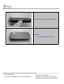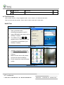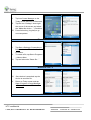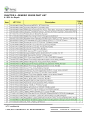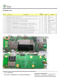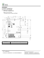
1
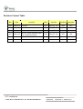
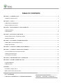
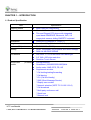
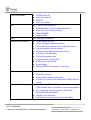
Herald
Service Manual
HTC Proprietary
Confidential Treatment Requested
Rev. A01
Nov 24, 2006
HTC Corp.
Engineering Mobility
HTC confidential
© 2006, HTC CORPORATION. ALL RIGHTS RESERVED.
TOTAL 58
CONT.ON. 2
PAGE NO. 1
Revision Control Table
Rev
Date
Contents
Dept.
Revised
App Dept
Stage/Per
AX01 2006/10/16 First Draft
PSE
Jerry W. Lin
GSD
DVT
AX02 2006/11/16 Add Procedure
PSE
Jerry W. Lin
GSD
PVT
AX03 2006/11/17 Add description
PSE
Jerry W. Lin
GSD
PVT
PSE
Jerry W. Lin
GSD
MV
A01
2006/11/24
Add L2.5, update keyboard upper
cover combine description
HTC confidential
© 2006, HTC CORPORATION. ALL RIGHTS RESERVED.
TOTAL 58
CONT.ON. 3
PAGE NO. 2
TABLE OF CONTENTS
CHAPTER 1 – INTRODUCTION .................................................................................................................................................... 4
1.1 PRODUCT SPECIFICATION ......................................................................................................................................................... 4
CHAPTER 2 – TOOLS ...................................................................................................................................................................... 8
2.1 REPAIR LEVEL DEFINITION ...................................................................................................................................................... 8
2.2 LIST OF SERVICING TOOLS........................................................................................................................................................ 8
CHAPTER 3 –DISASSEMBLING AND ASSEMBLING ............................................................................................................... 9
3.1 DISASSEMBLING ........................................................................................................................................................................ 9
3.2 ASSEMBLING ............................................................................................................................................................................ 18
CHAPTER 4 – DIAGNOSTIC PROGRAM .................................................................................................................................. 27
4.1 LIST OF DIAGNOSTIC / WINCE TEST ITEMS........................................................................................................................... 27
4.2 TEST PROCEDURE.................................................................................................................................................................... 28
CHAPTER 5 –SOFTWARE UPGRADE PRCEDURE................................................................................................................. 31
5.1 RUU (RE-FLASH UPGRADE UTILITY)..................................................................................................................................... 31
5.2 SD CARD UPGRADE .................................................................................................................................................................. 34
CHAPTER 6 –LEAKAGE CURRENT MEASUREMENT.......................................................................................................... 36
CHAPTER 7 – COSMETIC INSPECTION CRITERIA.............................................................................................................. 41
7.1 CLASSES DEFINITION OF INSPECTIVE AREA............................................................................................................................ 41
7.2 MAIN UNIT INSPECTION ........................................................................................................................................................... 42
7.3 COSMETIC OF CAMERA ........................................................................................................................................................... 45
CHAPTER 8 –TROUBLESHOOTING AND REPAIR................................................................................................................. 46
CHAPTER 9 –GENERIC SPARE PART LIST ............................................................................................................................. 51
9.1 SPL FOR REPAIR ...................................................................................................................................................................... 51
9.2 BOARD LEVEL ......................................................................................................................................................................... 52
APPENDIX........................................................................................................................................................................................ 53
A. GENERIC LABELING PLAN ....................................................................................................................................................... 53
B. RF ANTENNA TEST SPECIFICATION ......................................................................................................................................... 55
HTC confidential
© 2006, HTC CORPORATION. ALL RIGHTS RESERVED.
TOTAL 58
CONT.ON. 4
PAGE NO. 3
CHAPTER 1 – INTRODUCTION
1.1 Product Specification
Item
Specification
Soldering status
z
Meet Lead-free requirement
Platform
z
z
Microsoft Windows Pocket PC phone edition
Thin and Elegant PPC phone with integrated
quad-band GSM/EDGE, Bluetooth, WiFi, 2.0
mega-pixel camera, sliding QWERTY keyboard
Dimensions
z
59mm(W) x 109mm(H) x 17mm (T)
Weight
z
Less than 168 g (Main unit with battery pack)
Processor/Chipset
z
TI OMAP 850 + TI E-Syren
Memory
z
z
ROM: 128/256MB (for programs and users’ storage)
RAM: 64 MB DDR SDRAM
LCD Module
z
z
z
65K-color TFT LCD with white LED back light
2.8” 240 x 320 dots resolution
Sensitive Touch Screen
GPRS/GSM
module
(Tri-band) z
z
z
z
Internal Antenna
Quad-Band ( 850/900/1800/1900)MHz
Audio codec: AMR, EFR, FR, HR
Supplement services
* Call holding/waiting/forwarding
* Call barring
* CLI (Call line Identity)
* SMS (Short Message Service)
* Display own number
* Network selection(3GPP T2 23.122 V3.6.0)
* Cell broadcast
* Multi-party conference call
* Spool Icon
* Network lock
HTC confidential
© 2006, HTC CORPORATION. ALL RIGHTS RESERVED.
TOTAL 58
CONT.ON. 5
PAGE NO. 4
EDGE functionality
z
z
z
z
EGPRS Class B,
Multi-slot Class 10
PBCCH
PPP over GPRS
SIM
z
z
z
z
z
1.8V/3 V SIM Operation
SIM Application Tool Kit release 98 class 3
Over the Air (OTA) provisioning
FDN/AND/SDN
Support SIM+
Stylus
z
Lock type mechanism
Keyboard/Button/Switch
z
z
z
z
z
z
z
z
z
z
z
Power button (on top)
Comm. Manager (right side button)
Voice dial/Voice recorder button (right side button)
Camera capture (left side button)
Sliding Volume Up/Down(left side switch)
2 soft keys (left and right)
Five way navigation pad
2 phone button, Send & End
2 AP buttons, Start & OK
Reset Switch
Sliding QWERTY keyboard + 2 soft keys
Interface
z
z
z
z
1.8V/3V SIM card
Micro-SD card slot
External RF connector with cover
11 pins HTC specific mini-USB (Slave USB, Power IN,
Audio)
Notification
z
One Bi-color LED for GSM standby, GSM message,
GSM network status, notification, and charging status.
Two respective (blue and green) LEDs for for
Bluetooth/ WiFi notification.
Vibration for notificaiton
Notification by sound, message on the display.
z
z
z
HTC confidential
© 2006, HTC CORPORATION. ALL RIGHTS RESERVED.
TOTAL 58
CONT.ON. 6
PAGE NO. 5
CMOS Camera
z
z
CMOS 2.0 mega Pixel
Preview Mirror effect
Audio
z
z
z
z
z
Build-in Microphone
Receiver
Loud speaker for Hands-free supported
WAV/WMA/AMR/AAC/MP3 codec.
16 bits with 8KHz,11 KHz, 22KHz,44.1 KHz,
sampling rate
Audio Path Routing for VoIP over WLAN
Audio Echo Cancellation for VoIP over WLAN
z
z
Bluetooth
z
z
z
z
WiFi
z
z
z
z
z
z
Compliant with V2.0 without EDR
Class 2 transmit power
Supported profiles:
¾ Serial Port profile
¾ Object Push profile
¾ DUN profile
¾ Generic Object Exchange profile
¾ Headset profile
¾ Heads-free profile
¾ A2DP
¾ Audio/Video Remote Control profile
¾ Human Interface Device profile
¾ Service Discovery Application profile
¾ SIM Access profile
¾ File Transfer profile
Co-exist with WiFi
IEEE 802.11b/g compliant
Internal WLAN Antenna
Data rate auto fallback for extended range
ELP mode
Security
* WPA authentication
QoS
*Fast AP to AP handover (currently support Cisco AP)
HTC confidential
© 2006, HTC CORPORATION. ALL RIGHTS RESERVED.
TOTAL 58
CONT.ON. 7
PAGE NO. 6
Battery
z
z
z
z
z
Removable rechargeable Lithium Polymer battery
1130 mAH
Battery Life:
* WMA: 12 hours
* WMV: 8 hours
Talk time: 3.5 ~ 5 hrs
Standby Time: 150 ~ 200 hrs
AC Adapter
z
z
AC input 100 ~ 240 V AC, 50/60 HZ
DC output : 5V / 1A
Regulatory
z
z
z
GCF certification
R&TTE: EMC/EMI, CEM, Safety SAR
WiFi Certification
z
z
z
z
z
FCC
PTCRB
Bluetooth Qualification Body Certification
Microsoft Windows Mobile logo (NTSL)
USB Certification
z
z
z
z
z
z
z
z
z
z
z
z
Carrying Case
AC adapter with mini-USB plug
Sync. Cable (mini-USB)
Battery (rechargeable and replaceable)
Stereo wired headset with microphone
User Manual, quick start guide, sync. Software CD
Car adapter
Car holder
Wrist Strap
Cradle (optional)
Car Kit (optional)
Water resistant cover (optional)
Accessories
HTC confidential
© 2006, HTC CORPORATION. ALL RIGHTS RESERVED.
TOTAL 58
CONT.ON. 8
PAGE NO. 7
CHAPTER 2 – TOOLS
2.1 Repair Level Definition
Unit
L0
Accessory test and unit swap
L1
Unit Test and ROM Re-flash
L2
Refurbishment and Module Swap +L1
L2.5
M/B Repair(connecter, button, MIC…) +L2
Note : These level is for reference only depends on service model
2.2 List of Servicing Tools
level
L1
No.
Item
Use for
Remark
1
Mini USB DATA interface
Cable
Check for mini USB
communication; RUU re-flash
2
Earphone Headset
For Audio test.
3
AC Adapter
Transfer AC to DC for Unit
4
WLAN AP
For WiFi test
5
Micro SD Card with
For unit diagnostic test
Diagnostic test program (must
be encoded by HTC)
HTC design
6
128MB micro SD memory
card ( must be encoded by
HTC)
HTC design
7
Unit current consumption test
fixture
For unit ROM code transfer to
SD card for re-flash
HTC design
Measure Unit current
consumption
8
Power supply
9
Current Meter
10
Mobile tester
For RF test
Local purchase
11
Special Made Plastic Stick
Assembly & Disassembly
HTC special
Local purchase
Local purchase
tools
L2
L 2.5
12
Hand tools
Assembly & Disassembly
Local purchase
13
Label printer
Print agency label if replacing
M/B
Local purchase
14
Lead-free Soldering station
Board level repair
Local purchase
15
Air heater
Board level repair
Local purchase
HTC confidential
© 2006, HTC CORPORATION. ALL RIGHTS RESERVED.
TOTAL 58
CONT.ON. 9
PAGE NO. 8
CHAPTER 3 –DISASSEMBLING AND ASSEMBLING
3.1 Disassembling
Tools needed for Assembling and Disassembling
1. Glove & Lens Cleaning Tissue.
2. Plastic type tweezers.
3. Philip Screw Driver 000X40.
4. Philip Screw Driver T6X40
5. Flat Plastic Stick
Main Unit
1. Eject the Stylus.
2. Eject the micro SD card if available.
HTC confidential
© 2006, HTC CORPORATION. ALL RIGHTS RESERVED.
TOTAL 58
CONT.ON. 10 PAGE NO. 9
Release rear cover lock by pressing to right
Release battery
Unfasten 4 screws located on rear of unit
HTC confidential
© 2006, HTC CORPORATION. ALL RIGHTS RESERVED.
TOTAL 58
CONT.ON. 11
PAGE NO. 10
Release the antenna & speaker module
Disassembly C & D parts.
Carefully insert flat plastic stick into the gap
between C & D part. Be noticed this action
should be performed very carefully.
Using the flat stick and move along the gap of the
unit.
HTC confidential
© 2006, HTC CORPORATION. ALL RIGHTS RESERVED.
TOTAL 58
CONT.ON. 12 PAGE NO. 11
Release the housing
Unfasten one screw which fix the MB
Disassemble vibrator, and release keyboard FPC
HTC confidential
© 2006, HTC CORPORATION. ALL RIGHTS RESERVED.
TOTAL 58
CONT.ON. 13 PAGE NO. 12
Release board from its hook
Lift up the main board, release the LCM FPC and
take out the MB
Release Camera from its connector
HTC confidential
© 2006, HTC CORPORATION. ALL RIGHTS RESERVED.
TOTAL 58
CONT.ON. 14 PAGE NO. 13
Unfasten 6 screws located on C & D part (rear
housing)
Release keyboard
Unfasten 4 screws as shown on picture
HTC confidential
© 2006, HTC CORPORATION. ALL RIGHTS RESERVED.
TOTAL 58
CONT.ON. 15 PAGE NO. 14
Upper part dis-assembly
Release receiver
Unfasten two screws of RF board and two located on
metal dome
HTC confidential
© 2006, HTC CORPORATION. ALL RIGHTS RESERVED.
TOTAL 58
CONT.ON. 16 PAGE NO. 15
Release LCM FPC, separate RF board from
LCM
Release keypad from Bezel
Disassemble display bottom COVER
HTC confidential
© 2006, HTC CORPORATION. ALL RIGHTS RESERVED.
TOTAL 58
CONT.ON. 17 PAGE NO. 16
Unfasten the screws
Remove slider from bottom cover
Remove slider from its hinge
------ Disassembly process is done--------
HTC confidential
© 2006, HTC CORPORATION. ALL RIGHTS RESERVED.
TOTAL 58
CONT.ON. 18 PAGE NO. 17
3.2 Assembling
Assemble slider hinge
Align to its position
Put Slider into bottom cover
HTC confidential
© 2006, HTC CORPORATION. ALL RIGHTS RESERVED.
TOTAL 58
CONT.ON. 19 PAGE NO. 18
Assemble slider and fasten 6 screws
72H01701-00M
Torque: 1.1 +0.1 kg-cm
Assemble LCM and connect its FPC into RF
board
Put the RF board FPC to pass through slider hole
HTC confidential
© 2006, HTC CORPORATION. ALL RIGHTS RESERVED.
TOTAL 58
CONT.ON. 20 PAGE NO. 19
Maker sure FPC through the Slider
Fasten 4 screws of RF board to display bottom
cover
72H1715-00M
Torque: 0.8 +- 0.1kg-cm
Assemble receiver, put one tape to fix its wire
HTC confidential
© 2006, HTC CORPORATION. ALL RIGHTS RESERVED.
TOTAL 58
CONT.ON. 21 PAGE NO. 20
Put keypad on it
Continue with assemble the bezel,
Starting from left and right then to the top
HTC confidential
© 2006, HTC CORPORATION. ALL RIGHTS RESERVED.
TOTAL 58
CONT.ON. 22 PAGE NO. 21
Fasten 4 screws on display bottom cover
72H01706-00M
Torque: 0.8 +- 0.1kg-cm
Combine keyboard upper cover with display
bezel
keyboard upper cover
(combine with FPC/Keypad Qwerty key)
Need Fixture to assemble
Fasten 6 screws of keyboard upper cover
72H1696-00M
Torque: 0.8 +- 0.1kg-cm
HTC confidential
© 2006, HTC CORPORATION. ALL RIGHTS RESERVED.
TOTAL 58
CONT.ON. 23 PAGE NO. 22
Assemble Camera
Pull out the slider and connect LCM FPC into MB
Then stick LCM FPC with adhesive tape, plus
one tape to fix LCM FPC
Assemble MB by inserting into ring, put MB into
keyboard upper cover and fasten one screw on
it.(below camera)
Next, fasten the keypad FPC connector
72H1715-00M
Torque: 0.8 +- 0.1kg-cm
HTC confidential
© 2006, HTC CORPORATION. ALL RIGHTS RESERVED.
TOTAL 58
CONT.ON. 24 PAGE NO. 23
Assemble vibrator into MB and put it in keyboard
upper cover.
Then assemble MB into housing starting from its
USB connector
Check each button is assembly properly into its
position
HTC confidential
© 2006, HTC CORPORATION. ALL RIGHTS RESERVED.
TOTAL 58
CONT.ON. 25 PAGE NO. 24
Assemble antenna and speaker module starting
from its right lower part
Fasten 4 screws on rear side
72H01691H-00M
Torque 1.2 ± 0.1 kg-cm
Put battery in.
HTC confidential
© 2006, HTC CORPORATION. ALL RIGHTS RESERVED.
TOTAL 58
CONT.ON. 26 PAGE NO. 25
Assemble battery cover and lock it into position
Insert Stylus
------- Assembly process is done-------
HTC confidential
© 2006, HTC CORPORATION. ALL RIGHTS RESERVED.
TOTAL 58
CONT.ON. 27 PAGE NO. 26
CHAPTER 4 – DIAGNOSTIC PROGRAM
4.1 List of Diagnostic / WinCE Test Items
Mode
No
Item
Description
Remark
Diagnostic
Function Test
1
SDRAM Test
RAM memory test.
2
Display Test
Color bar/R/G/B/ White/Black/ /Gray pattern.
3
LED Test
Red/Green/ Blue/Key Pad.
4
Key Test
5
B. L Test
Front light test
6
Timer Test
RTC (Real time clock) test.
7
SD Card Test
SD card Read/Write test.
8
Mega SIM Test
Mega SIM card test.
9
Checksum Test
ROM checksum test.
10
Battery Test
Battery info check.
11
Vibrator Test
Vibrator on test.
12
Headset Play Test
Headset out test.
13
Speaker Play Test
Speaker out test.
14
Receiver Play Test
Receiver out test.
15
Int. Rec-Spk out Test
Internal MIC record and play to Speaker test.
16
Int. Rec-HST out Test
Internal MIC record and play to Headset test.
Capture/Volume up,down/Talk/Soft1/Start/Up/Right
/Down/Left/Action/Soft2/OK/End/PTT/WLAN/
Run-in Test
1
1 Hour
1 Hour Run-in Test/Press Soft1 key.
Option
2
2 Hours
2 Hours Run-in Test/Press Soft 2 key.
Option
3
4 Hours
4 Hours Run-in Test/Press Start key.
Option
4
8 Hours
8 Hours Run-in Test/Press OK key.
Option
Format FAT / Clear PIN (Personal information, talk times)
Win
CE
Device Info
1
USB Test
USB link test (Microsoft ActiveSync).
2
Camera Test
Camera test.
3
Bluetooth Test
Bluetooth test.
HTC confidential
© 2006, HTC CORPORATION. ALL RIGHTS RESERVED.
TOTAL 58
CONT.ON. 28 PAGE NO. 27
4
WLAN Test
WLAN test.
5
GPS Test
GPS test.
4.2 Test Procedure
How to select test item: Using navigation button -"Up" or "Down" or to select the test items
How to execute the test program: Press “Action” button to start each of test items.
WinCE Test
USB Test
I.
Start up the Microsoft®
ActiveSync®program in the PC.
II.
Insert USB cable and connect unit to
desktop/ or laptop.
III. The USB to PC icon
->
is
appears on the Today screen when
your device is connected to your
desktop/ or laptop.
Camera Test
I.
Tap Start->Program->Camera or
Press Camera button to turn on the
Camera.
II.
Make sure the device will present
and enter the preview display.
III.
Check camera pre-view and image
quality.
Bluetooth Test - 1
HTC confidential
© 2006, HTC CORPORATION. ALL RIGHTS RESERVED.
TOTAL 58
CONT.ON. 29 PAGE NO. 28
I.
Tap icon Comm Manager on the
Today screen and turn on Bluetooth.
II.
Tap the icon “Settings” down-right
the corner of the screen and select
the “Make this device….” Checkbox.
III. Press Action key (Jog-ball) to go
next test pattern.
Bluetooth Test - 2
I.
Tap Start->Settings->Connections->
Beam and select “Receive all….”
Checkbox.
II.
To create a file, tap Start->Programs
->Notes->New.
III.
Tap and select the “Beam file…”
Bluetooth Test - 3
IV. Once device is searched, tap the
device to send the file.
V.
Return to Today screen and tap
Start->Program->Comm Manager
->Bluetooth to turn off Bluetooth.
WLAN Test
HTC confidential
© 2006, HTC CORPORATION. ALL RIGHTS RESERVED.
TOTAL 58
CONT.ON. 30 PAGE NO. 29
I.
Tap icon Comm Manager on the
Today screen and turn on WLAN.
II.
Select the hot-spot/ or access point
which searchable and appears on
screen.
III.
Once the hot-spot (access point) is
connected, press the IE button and
logon Internet.
HTC confidential
© 2006, HTC CORPORATION. ALL RIGHTS RESERVED.
TOTAL 58
CONT.ON. 31 PAGE NO. 30
CHAPTER 5 –SOFTWARE UPGRADE PRCEDURE
System Requirement:
-Windows 2000/XP
-USB Cable
-ActiveSync 4.0 above
-Master Unit
-128 MB Mini SD card
Caution: The unit must have at least 70% of battery capacity before starting the re-flash process. Charge the
battery in advance if necessary.
For the master unit, you could prepare it in the following ways:
- Take one from Swap unit with the most up to date Rom Code.
- Build one first by connecting to SDO for OS Upgrade/ Download via RUU.
HTC RMAIII – Service Document Online: https://rma.htc.com.tw/rmaiii/home/index.asp
5.1 RUU (Re-flash Upgrade Utility)
Connect device to PC
I.
Setting and allow USB
connections in Microsoft
ActiveSync.
II.
Connect your device and
desktop/ or laptop via USB cable.
III. Check the pop-up message from
Microsoft ActiveSync when
device is synchronized with PC.
Download OS Image from SDO
HTC confidential
© 2006, HTC CORPORATION. ALL RIGHTS RESERVED.
TOTAL 58
CONT.ON. 32 PAGE NO. 31
I.
Download OS image from SDO.
http://htcscm10.htc.com.tw/SDO
II.
Un-zip the file and execute RUU
program.
III.
Follow instruction on your PC,
complete check box and “NEXT”
IV. On process will show your device
current ROM version, choose
“UPDATE”
HTC confidential
© 2006, HTC CORPORATION. ALL RIGHTS RESERVED.
TOTAL 58
CONT.ON. 33 PAGE NO. 32
V.
Confirm your ROM version and
new update version,then choose
“NEXT”
VI. Click “Next” to proceed.
VII. Read the information from pop-up message and the OS update procedure will takes
10 minutes long.
Click “Next” to proceed.
HTC confidential
© 2006, HTC CORPORATION. ALL RIGHTS RESERVED.
TOTAL 58
CONT.ON. 34 PAGE NO. 33
VIII. You can see the update progress
from your PC and in your device.
RUU - 7
IX. The OS upgrade is finished, click
“Finish” to close the utility.
Congratulation
5.2 SD card upgrade
Download OS Image from SDO
I.
Download OS image from SDO.
http://htcscm10.htc.com.tw/SDO
II.
Un-zip the image file.
Format SD card and copy image file to SD card
HTC confidential
© 2006, HTC CORPORATION. ALL RIGHTS RESERVED.
TOTAL 58
CONT.ON. 35 PAGE NO. 34
III.
Select file system and format the SD
card to FAT32 mode.
IV. Copy the image file XXX.nbh to
9
Micro SD card and rename to
HERAIMG.NBH.
SD Upgrade - 1
V.
Turn the device power off and insert
Diagnostic SD card.
VI. Press and hold Capture + Comm
MGR button, and Reset button to
entry Boot loader mode.
VII. Press power key to start upgrade
procedure.
[Note]: This process will takes 5 mins, please
don’t power off the device.
SD Upgrade - 2
VIII. Take out the SD card.
IX. Cold boot the device.
Now the upgrade is done!
Note: Due to security issue, it is not allowed to re-flash different customer ID.
HTC confidential
© 2006, HTC CORPORATION. ALL RIGHTS RESERVED.
TOTAL 58
CONT.ON. 36 PAGE NO. 35
CHAPTER 6 –LEAKAGE CURRENT MEASUREMENT
This is a quick method to measure if any abnormal leakage current on main board which caused high
power consumption compare to GOOD main board.
(1) Requirement:
- Power Supply
- Micro-current Meter
- Current series JIG
- CABLE
- Battery JIG
1.Equipment need:
A. Power Supply (set at 4 V /1A).
B. Micro-Current Meter (support 0.5mA ~ 1A).
B
A
2. Fixture needed
C. Cable
D. Battery with extension cable
E. Current series jig.( with black and red cable)
C
D
E
HTC confidential
© 2006, HTC CORPORATION. ALL RIGHTS RESERVED.
TOTAL 58
CONT.ON. 37 PAGE NO. 36
3. Connect cable (C) to positive polarity of power supply
(A) and current meter (B)
4. Connect cable of fixture( C ) to negative polarity of
power supply (A) and current meter (B)
Note : black cable to power supply (A) and
red cable to current meter (B)
5. Setting is Ready for testing
Assemble Battery into device.
( Don’t turn the power on at this moment )
Assemble Battery into device.
HTC confidential
© 2006, HTC CORPORATION. ALL RIGHTS RESERVED.
TOTAL 58
CONT.ON. 38 PAGE NO. 37
3. Connect cable (C) to positive polarity of
power supply (A) and current meter (B)
4. Connect cable of fixture( E ) to negative
polarity of power supply (A) and current
meter (B)
5. Setting is Ready now for testing
( Don’t turn the power on at this moment )
HTC confidential
© 2006, HTC CORPORATION. ALL RIGHTS RESERVED.
TOTAL 58
CONT.ON. 39 PAGE NO. 38
6.Turn on power supply ( 4V) and current
meter ( 2A)
Set the unit to :
* Flight mode
* Turn off Bluetooth
7. Measure flight mode current
Choice
Setting/System/Backlight/Brightness
Adjust brightness level to power save.
Current value must under 78mA, if
over, it means M/B failed, please
replace M/B for repair.
8. Switch OFF the unit.
Unit is turn off and no display.
9. Measure power off current
Check current value on the current
meter,
Current value must under 4.5 mA, if
over, it means M/B failed, please
replace M/B for repair.
Conclusion
HTC confidential
© 2006, HTC CORPORATION. ALL RIGHTS RESERVED.
TOTAL 58
CONT.ON. 40 PAGE NO. 39
I.
II.
If current consumption test PASS when UUT in Flight and Sleep mode, it means that the
M/B works normal.
If current consumption test FAIL when UUT in Flight or Sleep mode, it means that the M/B
works abnormal, please replace M/B and re-test again.
HTC confidential
© 2006, HTC CORPORATION. ALL RIGHTS RESERVED.
TOTAL 58
CONT.ON. 41 PAGE NO. 40
CHAPTER 7 – COSMETIC INSPECTION CRITERIA
1.1
This document based on the experience of customer’s requirements is designated as HTC internal quality
inspection standard of HERALD series products for HTC.
1.2
These cosmetic criteria should be applied in QC1, QC2 and CDIT stations. Regarding functional inspection of
CDIT, please refer to CDIT SIP.
7.1 Classes definition of inspective area
7.2.1 (Class 1 area ):
Class 1 area => The front side of main unit involve all buttons and LED lens except
7.2.2 (Class 2 area ):
Class 2 area =>The view of Qwerty keyboard after slid out main unit (involve stylus)
7.2.3 (Class 3 area ):
Class 3 area => 4 sides and back views of main unit.
7.2.4 (Class 4 area ):
Class 4 area =>Socket of battery, inner side of battery cover and back side of upper part.
*. Figure
1:
( Photo of inspection areas )
第 2 區 Class 2
第1區
Class 1
第 4 區 Class 4
HTC confidential
© 2006, HTC CORPORATION. ALL RIGHTS RESERVED.
第 3 區 Class 3
TOTAL 58
CONT.ON. 42 PAGE NO. 41
7.2 Main unit inspection
7.3.1 System assembly inspection :
-Exposure of substratum is not acceptable for peeling. (Area 4 is included)If not exposure of
substratum, please checked by SPEC. of dot or scratch. (Area 4 is not included)
-Logo may not have blurred or double print., the peeling on logo is not acceptable.
-The character printing of main unit does not allow bad printing,scratch,dirty, lacquer
peeling ,dark/white dot on it)
- Camera lens dot, particle D≦0.25mm;burr ≦1.5mm , W≦0.2mm ,
1.
(Gap inspection )
Description
Accept criteria
Level
1. Status of main unit assembly.
Defective assembly and deformed shape were nor allowed.
Minor
2. Gap between touch panel and bezel.
Gap between touch panel and bezel < 0.7 mm
(Skip corner and Enter the material to click)
Minor
3. Gap between upper / lower slid parts.
Gap between upper / lower slid parts < 1..0 mm
Minor
4. Qwerty key Gap and around Gap
Between key Gap<0.35 mm, Edge of key and C-part Gap
<0.4 mm
Minor
5.
Gap between navigation key and (gap) <0.35 mm
AP keys assembly.
Key stuck are not allowed.
Minor
6.
Gap around power button, record (gap) <0.35 mm
button, volume key, camera button Key stuck are not allowed
Minor
7. Stylus
8.
Gap between battery cover and
main unit.
Stylus assembly protruding, loose, missing, falling
and deformed is not allowed.
D,E parts(gap) <0.50 mm
Minor
Minor
HTC confidential
© 2006, HTC CORPORATION. ALL RIGHTS RESERVED.
TOTAL 58
CONT.ON. 43 PAGE NO. 42
9
A,B part (gap) <0.3 mm, around stylus (gap) <0.65
Gap between other mating parts. mm
C part (gap) <0.3 mm
Minor
A,B parts (gap) <0.3 mm, Stylus near key
(gap) :0.4mm
Stylus near key (gap)
Edge of C-part (gap) <0.3 mm
B/C-part front and rear GAP Tolerance<0.1mm
GAP≦0.9mm(Key stuck are not allowed)
Minor
10
& APP key hight≦0.9mm
APP KEY around GAP
2. (Step inspection )
Description
Accept criteria
Level
1. Step between upper / lower slid parts.
(Step) < 0.50 mm
Minor
2. Others between upper / lower parts.
(Step) < 0.40 mm
Minor
Cosmetic inspection:
1. (Scratch )
Description
Accept criteria
Level
Class 1/Class 2 /Class 3
Class 2/ stylus
Exposure of substratum is not acceptable
Scratch : L≦7mm ,W≦0.25mm ,N≦3, S≧10mm
Minor
Bright mark area should be less than 1 mm x 10 mm
Class 4
label
Any damaged marks, shortage of plating and printing are
not acceptable.
Minor
Wrong printing or illegible print be not allowed.
Minor
HTC confidential
© 2006, HTC CORPORATION. ALL RIGHTS RESERVED.
TOTAL 58
CONT.ON. 44 PAGE NO. 43
2. (Contamination dot/Granule dot/Cave granule
Description
)
Accept criteria
Level
Class 1/Class 2 /Class 3
MS logo Spot
D≦0.25mm,N≦1
Minor
3. (Burr….etc.)
Description
Edge damage on all mating parts
2. Burr.
Accept criteria
Level
L≤3mm, W≤0.254mm
Minor
W: 0.25mm Max, sharp edge is not acceptable
Minor
4. (Imprint mark )
Description
Accept criteria
Level
Class 1/Class 2 /Class 3 Cosmetic inspection refer to IS-3047
5. (Bright mark )
Description
Accept criteria
Level
Class 1/Class 2 /Class 3 Cosmetic inspection refer to IS-3047
6. (Lint)
Description
Accept criteria
Level
Class 1/Class 2 /Class 3 Cosmetic inspection refer to IS-3047
P.S. Definition of lint identification
This definition is not applicable to LCM.
W
L
HTC confidential
© 2006, HTC CORPORATION. ALL RIGHTS RESERVED.
TOTAL 58
CONT.ON. 45 PAGE NO. 44
7.3 Cosmetic of Camera
Symptom
Glue
Line, Lint
Standard
Defect
model
Inner glass
Accept
Minor
Out side glass
Over to black area not accept
Inner glass
W≦0.25 mm and L≦ 3.0 mm , N≦1
Minor
Should not affect to picture quality
Spot
Out side glass
Over to black area not accept
Inner glass
D≦0.25, N≦1
Minor
HTC confidential
© 2006, HTC CORPORATION. ALL RIGHTS RESERVED.
TOTAL 58
CONT.ON. 46 PAGE NO. 45
CHAPTER 8 –TROUBLESHOOTING AND REPAIR
Before repairing, please try to duplicate if the symptom exist or Customer mishandling
1-A.Main Unit Does Not Respond to Power Button
1-B.Main Unit Does Not Respond to Battery Switch
1-C.Charge light is red when plug in AC adapter
(1) Make sure the Battery is installed properly to activate the battery pack.
(2) Connect the AC Adapter, maybe the battery pack is exhaust.
(3) Check the Battery cover is close properly.
(4) Try with another battery pack.
(5) Replace battery pack if necessary.
(6) Try to enter boot loader mode, Perform Re-flash OS if successfully.
(7) CMOS Camera is not assembled properly.
(8) Check all connections including LCD FPC to Main Board. Try with another Main Board.
(9) Fuse blown .
(10) Customer abuse caused the power button fallen off
(11) Both item 9 & 10 , MB replacement is necessary unless you are authorized to do board level repair.
(12) If Charge light is red when plug in AC adapter, it means the main battery is not charge enough and can’t power on,
You just need to continue charge unit the light become Amber.
(13) Once the defective part has been identified, verify it again with the defective part whether the
symptom could be duplicated.
2-A.Touch Panel Does Not Respond to Screen Tap
(1) Dismantle the unit, check the perimeter of Display between display Bezel and Touch Panel
surface for unusual foreign objects. Clean it, reassemble the unit and check the panel’s
function again.
(2) Check the connection of LCM FPC whether is properly connected.
(3) Try with another LCM.
(4) Try with another Rigid-Flex board.
(5) Try with another Main Board.
(6) Replace LCM if necessary
(7) Replace Main Board if necessary.
(8) Once the defective part has been identified, verify it again with the defective part whether the
symptom could be duplicated.
HTC confidential
© 2006, HTC CORPORATION. ALL RIGHTS RESERVED.
TOTAL 58
CONT.ON. 47 PAGE NO. 46
2-B.Buttons Do Not Respond
(1) Dismantle the unit, check the status of switches on the Main Board and the plastic parts of
button of the Button not responding.
(2) Try with another Main Board, rigid-Flex or keypad.
(3) Replace Main Board, rigid-Flex or keypad if necessary.
(4) Once the defective part has been identified, verify it again with the defective part whether
the symptom could be duplicated.
(5 ) Hard Reset The unit.
3-A.Unusual Vertical / Horizontal lines or partial display
(1) Check the connection of LCM FPC whether is properly connected.
(2) Try with another LCM.
(3) Try with another Rigid-Flex board
(4) Try with another Main Board.
(5) Replace LCM if necessary
(6) Replace rigid-Flex board if necessary
(7) Replace Main Board if necessary.
(8) Once the defective part has been identified, verify it again with the defective part whether the
symptom could be duplicated.
3-B.Back Light Does Not Turn ON/OFF
(1) Check the connection of FPC whether is properly connected.
(2) Try with another LCM.
(3) Try with another Rigid-Flex board
(4) Try with another Main Board.
(5) Replace LCM if necessary
(6) Replace rigid-Flex board if necessary
(7) Replace Main Board if necessary.
(8) Once the defective part has been identified, verify it again with the defective part whether the
symptom could be duplicated.
HTC confidential
© 2006, HTC CORPORATION. ALL RIGHTS RESERVED.
TOTAL 58
CONT.ON. 48 PAGE NO. 47
4-A-SD Card cannot be used
(1) Check whether SD is fully inserted to the slot until you hear a click.
(2) Try with another SD Card
(3) Try with another Main Board.
(4) Replace Main Board if necessary.
(5) Once the defective part has been identified, verify it again with the defective part whether the
symptom could be duplicated.
5-A.PC Connection (USB) not possible
(1) Check whether “Connection Settings” in the MS ActiveSync is properly set.
(2) Check whether it connects with other cables or cradle, customer’s cable might be damaged.
(3) Check the external appearance of the connector on the unit whether it is physically damaged.
(4) Replace Main Board if necessary.
(5) Once the defective part has been identified, verify it again with the defective part whether the
symptom could be duplicated.
5-B.Wireless Connection (GSM / GPRS / BT / WLAN) not possible
(1) Make sure the user has been contacting the Carrier for SIM Card validation and activation.
(2) Make sure the Wireless Connection Settings has been properly set.
(3) Make sure the SIM Card is properly inserted to the SIM compartment. Make a life call or test
it with the RF Test Station (Antenna Test).
(4) Dismantle the Main Unit and check whether the Antenna cover is properly installed.
(5) Try with another Antenna cover.
(6) Try with another Main Board if necessary.
(7) Once the defective part has been identified, verify it again with the defective part whether the
symptom could be duplicated.
HTC confidential
© 2006, HTC CORPORATION. ALL RIGHTS RESERVED.
TOTAL 58
CONT.ON. 49 PAGE NO. 48
5-C.IrDA Connection not possible
(1) Make sure the IrDA port settings on the Notebook or PC are properly set.
(2) Make sure the IrDA function is properly activated on the Pocket PC and on the other device.
(3) Make sure there’s no obstruction between the two devices in connection and within the distance.
(4) Check the IrDA window whether it is broken or cracked. Replace Front Bezel if necessary.
(5) Replace Main Board if necessary.
(6) Once the defective part has been identified, verify it again with the defective part whether the
symptom could be duplicated.
6-A.Main Battery does not start
(1) Make sure the Battery cover is closed properly.
(2) Connect to the AC Adapter and see if it takes charge. Also check AC Adapter condition.
(3) Check whether AC Adapter is functioning properly.
(4) Check whether the condition of Battery Charging status is correct.
(5) Dismantle the unit and check the appearance of Battery cover.
(6) Try with another Main Board or Replace Main Board if necessary.
(7) Once the defective part has been identified, verify it again with the defective part whether the
symptom could be duplicated.
.
6-B.Battery discharges quickly even after fully charged
(1) Make sure the Battery Pack takes fully charge with AC Adapter.
(2) Check whether the condition of Battery Charging status is correct.
(3) Dismantle the unit and check the appearance of Battery cover.
(4) Try with another Battery or Replace Battery if necessary
(5) Try with another Main Board or Replace Main Board if necessary.
(6) Once the defective part has been identified, verify it again with the defective part whether the
symptom could be duplicated.
HTC confidential
© 2006, HTC CORPORATION. ALL RIGHTS RESERVED.
TOTAL 58
CONT.ON. 50 PAGE NO. 49
7-C.Main Battery does not recharge
(1) Make sure the Battery takes fully charge with AC Adapter.
(2) Check whether the condition of Battery Charging status is correct. Charge should be done
in no more than 3 hours.
(3) Dismantle the unit and check the appearance of Battery cover.
(4) Try with another Battery or Replace Battery if necessary
(5) Try with another Main Board or Replace Main Board if necessary.
(6) Once the defective part has been identified, verify it again with the defective part whether the
symptom could be duplicated.
8-A.No Sound from Speaker or Distorted sound
(1) Check “Sound & Notifications” Settings in the unit for Sound Enabling.
(2) Make sure it’s not MUTED.
(3) Dismantle and Check whether the Speaker is properly installed (Orientation)
(4) Make sure the connection point between MB and Speaker is free from contamination or dust.
(5) Replace Speaker if necessary.
(6) Replace Main Board if necessary.
(7) Once the defective part has been identified, verify it again with the defective part whether the
symptom could be duplicated.
(8) Replace Camera if camera function was defect at the same time.
9-A.No Recorded Sound or Distorted sound
(1) Check “Sound & Notifications” Settings in the unit for Sound Enabling.
(2) Make sure it’s not MUTED.
(3) Dismantle and Check whether the Microphone is properly installed (check or missing rubber)
(4) Replace Microphone if necessary.
(5) Replace Main Board if necessary.
(6) Once the defective part has been identified, verify it again with the defective part whether the
symptom could be duplicated.
10-A.Bezel, Housing Cosmetic damage
(1) Unless it is for Refurbishment, all Bezel, housing replacement due to cosmetic damage shall treat
as out of warranty
HTC confidential
© 2006, HTC CORPORATION. ALL RIGHTS RESERVED.
TOTAL 58
CONT.ON. 51 PAGE NO. 50
CHAPTER 9 –GENERIC SPARE PART LIST
9.1 SPL for Repair
HTC confidential
© 2006, HTC CORPORATION. ALL RIGHTS RESERVED.
TOTAL 58
CONT.ON. 52 PAGE NO. 51
9.2 Board Level
SW 4
SW 7
CON1
A M IC 1
CON2
SW 1
SW 5
CON9
PC O N 1
SW 6
SW 3
CON6
CON5
ACON1
CON3
HTC confidential
© 2006, HTC CORPORATION. ALL RIGHTS RESERVED.
TOTAL 58
CONT.ON. 53 PAGE NO. 52
APPENDIX
A. Generic Labeling Plan
A1 Agency label-W/ WiFi
HTC P/N: 77H00385-00M
Size: 41.8 X 62.1mm
The brand name is shown on Bezel.
HTC P/N
Countries supported
HTC confidential
© 2006, HTC CORPORATION. ALL RIGHTS RESERVED.
TOTAL 58
CONT.ON. 54 PAGE NO. 53
A2 Agency label-W/O WiFi
HTC P/N: 77H00385-04M
Size: 41.8 X 62.1mm
The brand name is shown on Bezel.
HTC P/N
Countries supported
HTC confidential
© 2006, HTC CORPORATION. ALL RIGHTS RESERVED.
TOTAL 58
CONT.ON. 55 PAGE NO. 54
B. RF Antenna Test Specification
Item
Test Name
Tx level
TCH
1st Download cell
power
1
Camp @DCS Band
0
512
-75
2
BS Originate call
0
512
-75
Note
BCH=600
E-GSM 900 RECEIVER TEST
3
Fast Bit Error Rate
5
975
-104
4
Fast Bit Error Rate
5
42
-104
5
Fast Bit Error Rate
5
124
-104
E-GSM 900 Transmitter TEST
6
TX Phase RMS Error
5
975
-104
7
TX Phase Peak Error
5
975
-104
8
TX Frequency Error
5
975
-104
9
TX Phase RMS Error
5
42
-104
10
TX Phase Peak Error
5
42
-104
11
TX Frequency Error
5
42
-104
12
TX Phase RMS Error
5
124
-104
13
TX Phase Peak Error
5
124
-104
14
TX Frequency Error
5
124
-104
15
Check TX Power
5
975
-104
16
Check TX Power
5
42
-104
17
Check TX Power
5
124
-104
DCS 1800 Receiver Test
1
Fast Bit Error Rate
0
512
-104
2
Fast Bit Error Rate
0
698
-104
3
Fast Bit Error Rate
0
885
-104
DCS 1800 Transmitter Test
4
TX Phase RMS Error
0
512
-104
5
TX Phase Peak Error
0
512
-104
6
TX Frequency Error
0
512
-104
7
TX Phase RMS Error
0
698
-104
HTC confidential
© 2006, HTC CORPORATION. ALL RIGHTS RESERVED.
TOTAL 58
CONT.ON. 56 PAGE NO. 55
8
TX Phase Peak Error
0
698
-104
9
TX Frequency Error
0
698
-104
10
TX Phase RMS Error
0
885
-104
11
TX Phase Peak Error
0
885
-104
12
TX Frequency Error
0
885
-104
13
Check TX Power
0
512
-104
14
Check TX Power
0
698
-104
15
Check TX Power
0
885
-104
PCS 1900 Receiver Test
1 Fast Bit Error Rate
0
512
-104
2 Fast Bit Error Rate
0
661
-104
3 Fast Bit Error Rate
0
810
-104
PCS 1900 Transmitter Test
4
TX Phase RMS Error
0
512
-104
5
TX Phase Peak Error
0
512
-104
6
TX Frequency Error
0
512
-104
7
TX Phase RMS Error
0
661
-104
8
TX Phase Peak Error
0
661
-104
9
TX Frequency Error
0
660
-104
10
TX Phase RMS Error
0
810
-104
11
TX Phase Peak Error
0
810
-104
12
TX Frequency Error
0
810
-104
13
Check TX Power
0
512
-104
14
Check TX Power
0
661
-104
15
Check TX Power
0
810
-104
GSM 850 Receiver Test
1 Fast Bit Error Rate
5
128
-104
2 Fast Bit Error Rate
5
189
-104
3 Fast Bit Error Rate
5
251
-104
GSM 850 Transmitter Test
4
TX Phase RMS Error
5
128
-104
HTC confidential
© 2006, HTC CORPORATION. ALL RIGHTS RESERVED.
TOTAL 58
CONT.ON. 57 PAGE NO. 56
5
TX Phase Peak Error
5
128
-104
6
TX Frequency Error
5
128
-104
7
TX Phase RMS Error
5
189
-104
8
TX Phase Peak Error
5
189
-104
9
TX Frequency Error
5
189
-104
10
TX Phase RMS Error
5
251
-104
11
TX Phase Peak Error
5
251
-104
12
TX Frequency Error
5
251
-104
13
Check TX Power
5
128
-104
14
Check TX Power
5
189
-104
15
Check TX Power
5
251
-104
HTC confidential
© 2006, HTC CORPORATION. ALL RIGHTS RESERVED.
TOTAL 58
CONT.ON. 58 PAGE NO. 57
HTC confidential
© 2006, HTC CORPORATION. ALL RIGHTS RESERVED.
TOTAL 58
CONT.ON. F
PAGE NO. 58