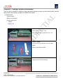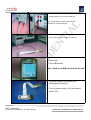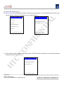
1
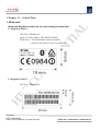
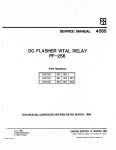
L
IA
NF
ID
EN
T
Service Manual
for Feelers
CO
HTC Proprietary
Confidential Treatment Requested
Rev. A01
HT
C
Nov 01, 2004
HTC Corp.
Engineering Mobility
HTC confidential
© 2003, HTC Corporation. All rights reserved.
TOTAL 65
CONT.ON. 2 PAGE NO. 1
TITLE: Service Manual for Feelers
DATE
CONTENTS
DEP.
A01
11/01
First reversion
TSE
REVISED APP’D
STGE.PER.
HT
C
CO
NF
ID
EN
T
IA
L
REV.
NO.
HTC confidential
© 2003, HTC Corporation. All rights reserved.
TOTAL 65
CONT.ON. 3 PAGE NO. 2
Table of contents
5
IA
L
Chapter 1 - Introduction
1.1
History
Chapter 2 - Product Specifications
6
EN
T
Chapter 3 - Servicing Tools
Chapter 4 - Assembling and Disassembling
4.1 Disassembling
4.2 Assembling
NF
ID
Chapter 5 - Diagnostic Programs
8
9
24
5.1 List of Test Items (Diagnostics in SD card)
5.2 Test Procedure
5.3 Test Result
Chapter 6 - Battery Test Procedure
Fixture
CO
6.1 Leakage current measurement with
6.2 Battery Capacity Test
28
Chapter 7 - Software Upgrade procedure
34
HT
C
7.1 Software upgrade
7.2 Smartphone Reset
7.4 Software Backup to SD card
Chapter 8 - RF Antenna test spec and criteria
42
8.1 Antenna Test Specification
8.2 Antenna Test Criteria
HTC confidential
© 2003, HTC Corporation. All rights reserved.
TOTAL 65
CONT.ON. 4 PAGE NO. 3
Chapter 9 - Inspection Criteria
45
IA
L
9.1 Definition
9.2 Inspection Area
9.3 Criteria
46
Chapter 11 - Labeling Plan
Chapter 12 - Spare parts list
NF
ID
12.1 Spare parts list for repair
12.2 Accessory Spare parts list
12.3 Board level parts list
EN
T
Chapter 10 - Trouble Shooting
Chapter 13 - Board Level Repair
53
57
62
HT
C
CO
13.1 Components to be Replaced
13.2 Problem Identification &Troubleshooting
HTC confidential
© 2003, HTC Corporation. All rights reserved.
TOTAL 65
CONT.ON. 5 PAGE NO. 4
Chapter 1 - Introduction
1.1 History
Reversion
Pages effected
First release
N/A
HT
C
CO
NF
ID
EN
T
A01
Update item
IA
L
This manual provides the technical information to support the service activities of Feelers.
Feelers .It contains highly confidential information, so any or all of this document should not be
revealed to any third party.
HTC confidential
© 2003, HTC Corporation. All rights reserved.
TOTAL 65
CONT.ON. 6 PAGE NO. 5
Chapter 2 - Product Specifications
107.54mm(L) x 46.2mm(W) x 17/17.5mm(T)
Weight
100g with battery
CPU
TI OMAP 730 tri-band GSM/GPRS solution
Memory
SDRAM:32MB
Flash ROM:64MB
Tri-band 900/1800/1900
GPRS, Class B
Multi-slot class 10
2.2 inch, 176x220 dots resolution
LED back Light
64K colors, TFT transflective LCD
GSM Function
Display
EN
T
Dimensions
L
Specification
OS: Microsoft Windows Mobile Smartphone
IA
Function
Platform
One Power Button (On the Top)
One Numeric Dialing Keypad(12 buttons)
Two soft key button
One Home/connection quick list button
One Back button
Send/Phone button
End Phone button
One 5- way navigation keypad
One Camera Capture button
Volume up button (Long Press as voice record)
Volume down button(long press as Voice command/Dial.
Interface
3.0 V SIM Card.
One mini-USB connector (Slave USB, Power IN)
One Infrared IrDA SIR.
One Mini SD memory card slot
One external antenna connector.
CO
HT
C
Power
NF
ID
Keyboard/Button
Device to device
connectivity
CMOS Camera
Talk: 3.5~4 hours
Standby: 140 hours
Standard Battery
Rechargeable battery, Li-Ion 970 mAh
AC Adapter:
AC input rating: 100 ~ 240 VAC, 50/60Hz
DC output rating: 5VDC, 1A
Ambient light sensor for LED power consumption
Bluetooth
Infrared IrDA SIR
USB mini-B plug and receptacle
Color
Resolution: VGA
Min 5 Lux
Preview Mirror
HTC confidential
© 2003, HTC Corporation. All rights reserved.
TOTAL 65
CONT.ON. 7 PAGE NO. 6
Notification
One Bi-color LED (Green and Red) for GSM STANDBY, GSM standby,
GSM network status, Event Notification, Power charging status.
One Blue LED for Bluetooth connectivity status.
Vibration for notification and Incoming call.
Notification by LED, Sound, Message, Vibration Motor.
Bundle:
AC adapter w/ DC_In mini USB plug
USB Sync cable
Stereo wired headset with Microphone
Standard Battery
User Manual, Quick Start Guide, Sync. Software CD
IA
L
Accessories
HT
C
CO
NF
ID
EN
T
Option
Car Adapter
Traveler Charger with back up battery charging slot
Car kit with Car Stereo Mute function
Carrying case
HTC confidential
© 2003, HTC Corporation. All rights reserved.
TOTAL 65
CONT.ON. 8 PAGE NO. 7
Chapter 3 - Servicing Tools
List of Servicing Tools
No.
Item
Use
L
This chapter provides information for the servicing tools for Feelers.
Remark
Disassembly tools
2
Mini USB cable
Plastic stick for dismantle the unit
Cleaning wipers
Precision screw driver 0.9mm
Philips Screw driver
Protective Film
Tweezers
Air Gun
Clean Bench (Mandatory)
For Synchronization Test
3
Mini SD Memory Card
For SD card test
4
Headset
For Hand free / Recording test
5
AC Adapter with DC In mini
USB plug
Diagnostic Test Program
Power supply to Typhoon
8
Software Upgrade tools
Label Printer & Scanner
For software version upgrade or re-flash
For Printing & Scanning regulation label when
housing or M/B is changed.
9
Battery Test Jig
EN
T
Test Program for Functional Test
For Main Battery judgement
HT
C
CO
7
NF
ID
6
IA
1
HTC confidential
© 2003, HTC Corporation. All rights reserved.
TOTAL 65
CONT.ON. 9 PAGE NO. 8
Chapter 4 - Assembling and Disassembling
4.1 Disassembling
EN
T
IA
L
Tools needed for Assembling and
Disassembling the Smart Phone
1. Glove & Lens Cleaning Tissue.
2. Plastic type tweezer.
3. Philip Screw Driver #0.
4. Philip Screw Driver type T5
5. Special Made Plastic Stick
NF
ID
Disassembly process
Front side
HT
C
CO
Rear Side
Remove antenna rubber, battery cover, battery
from unit
HTC confidential
© 2003, HTC Corporation. All rights reserved.
TOTAL 65
CONT.ON. 10 PAGE NO. 9
To remove antenna cover
Please use Precision driver flat(θ) type 1.2 mm
and insert in to the two hole as shown on
picture.
IA
L
Insert in angle:30 °
1
2
6
HT
C
CO
5
4
NF
ID
EN
T
TIPS:
Insert the driver to the hole with angle about 30
degree , after reach the end, move back
around 1mm and press it down to release the
the cover lock.
1. Remove the cover from its place.
2. Unscrew 6 ea screws which fix rear cover
to front panel.
3
Next, start disassembly the rear cover.
Please be noticed that improper way of
disassembly may caused the cover worn easily
1. Insert the plastic stick to the gap between
front and rear cover deep inside.
2. Move the stick slightly from lower side to
upper to release the rear cover
HTC confidential
© 2003, HTC Corporation. All rights reserved.
TOTAL 65
CONT.ON. 11 PAGE NO. 10
IA
L
Release all hooks at both side.
NF
ID
EN
T
Remove the rear cover
Next remove one screw which fix the MB to
front case.
Following to release the LCD FPC .
HT
C
CO
To take out the upper half part, hold the MB
together with the LCD at the upside part near
antenna
MB+LCD have been remove from front panel.
Please keep the LCD at clean surface.
HTC confidential
© 2003, HTC Corporation. All rights reserved.
TOTAL 65
CONT.ON. 12 PAGE NO. 11
IA
L
Take off the Camera module
NF
ID
EN
T
Next, remove the LCD from MB. Please notice
that there are two double sides tape sticked
between LCD and its FPC.
HT
C
CO
These two tapes are reusable for assembly.
Release the LCD Connector cover to remove
the LCD from its connector by pulling upward.
Put the LCD to clean and safe place.
HTC confidential
© 2003, HTC Corporation. All rights reserved.
TOTAL 65
CONT.ON. 13 PAGE NO. 12
IA
L
Now MB is separated from LCD
NF
ID
EN
T
Continue with Front panel disassembly
HT
C
CO
Disassembly the switch board.
1. Release two screws which tighten the
switch board to front panel.
2. Take out the switch board.
Remove the numeric keypad, function
keypad and Navigation keycap from the
switch board.
HTC confidential
© 2003, HTC Corporation. All rights reserved.
TOTAL 65
CONT.ON. 14 PAGE NO. 13
NF
ID
EN
T
Numeric keypad
IA
L
Remove the numeric keypad from the front
panel.
HT
C
CO
Remove the Navigation CAP directly.
Pull the switch board at its top, release the
APP functional keypad.
Push the switch board from rear side (to
front side), same step applied to right side.
HTC confidential
© 2003, HTC Corporation. All rights reserved.
TOTAL 65
CONT.ON. 15 PAGE NO. 14
step3
step4
L
step2
EN
T
IA
step 1
Remove the Switch board
Step 1 : Use plastic tool to pull the switch
board out.
Step 2 : Pull out the switch board connector
first.
Step 3: Same step is applied along the
switch board, as shown on picture.
Step 4: Remove the adhesive tape which fix
the switch board to metal support.
Step 5 : Same step to its right side.
Step 6 : Follow step shown on picture to
take out the switch board from the center
hole of metal support.
step5
NF
ID
Done.
step6
To disassembly speaker
Slightly release it from its lower left part.
1.Release three screws which tighten the
speaker to front panel.
2.Take off the speaker.
HT
C
CO
Done.
HTC confidential
© 2003, HTC Corporation. All rights reserved.
TOTAL 65
CONT.ON. 16 PAGE NO. 15
EN
T
CMOS camera.
IA
L
Remove the Vibrator from its place.
NF
ID
If you send this part as RTV(return to vendor),
please protect (pack) it in appropriate way ,
otherwise broken parts will be treated as OOW
HT
C
CO
Disassembly process is Done.
HTC confidential
© 2003, HTC Corporation. All rights reserved.
TOTAL 65
CONT.ON. 17 PAGE NO. 16
4.2
Assembly Process
L
Assembly vibrator into its place on rear cover.
Notice:Use air gun to clean Camera 、bezel,
and check surface to avoid the particle
IA
震動器
喇叭
Speaker
EN
T
Vibrator
Assemble Receiver into its place, notice the
two pin should not bent on assembly process.
NF
ID
Notice: Receiver coming as spare part already
has double side tape on it, you could remove
the top layer and stick it on front panel.
HT
C
CO
Assemble the numeric keypad.
Put the Navigation keycap, functional keypad
and switch board into front panel.
HTC confidential
© 2003, HTC Corporation. All rights reserved.
TOTAL 65
CONT.ON. 18 PAGE NO. 17
IA
Torque:0.5 ±0.1 kgf-cm
L
Fasten four screws to fix switch FPC board
with its metal support.
Notice the two guide points is fixed.
NF
ID
EN
T
Besides of above two guide pins, need to
adjust additional two guide pins as shown on
picture.
HT
C
CO
Next for MB part.
Insert the FPC into its connector.
Please notice to align the first white line for
type 1 LCD(Green type)
Second white line is for another type
LCD( Brown type).
Remark: Make sure the LCD is installed
properly.
HTC confidential
© 2003, HTC Corporation. All rights reserved.
TOTAL 65
CONT.ON. 19 PAGE NO. 18
IA
L
Place the LCD into its place
Before assembly the front panel, please check
NF
ID
EN
T
the receiver pin is not deformed.
Hold the MB together with LCD into front
panel. Please pay attention to Receiver PIN.
HT
C
CO
Please notice not to contrict to receiver pin
which may cause pin deformed.
Place the MB into the front panel and adjust it
to the guide hole at the lower right side, as the
fix position reference
Assemble the Switch board FPC connector.
Fasten the screw which fix the MB to front
panel.
Torque:0.7±0.05 kgf-cm
HTC confidential
© 2003, HTC Corporation. All rights reserved.
TOTAL 65
CONT.ON. 20 PAGE NO. 19
EN
T
IA
L
Now to assemble rear cover.
Close it
NF
ID
Then assemble the Antenna cover with the
unit, fix it to its hook.
Fasten four screws located on the upper &
lower of unit.
HT
C
CO
Torque:1±0.1 kgf-cm
Do remember to put Security label(warranty
seal on the top of screw (right)
HTC confidential
© 2003, HTC Corporation. All rights reserved.
TOTAL 65
CONT.ON. 21 PAGE NO. 20
IA
L
Install battery, battery cover, antenna rubber
cover into unit
NF
ID
EN
T
Lock the battery cover
HT
C
CO
Now unit is ready for functional test
Assembly process is DONE.
HTC confidential
© 2003, HTC Corporation. All rights reserved.
TOTAL 65
CONT.ON. 22 PAGE NO. 21
4.3 MB Pre-assembly
Parts that need to pre-assembled first upon replacing to new one:
(1)Main board.
9
4
7
8
3. Poron, LCD Ground,(qtty 2), : 76H00596-00 [7~8]
10
6
4. Gasket,U-tek : 76H00595-00 (QTTY: 2) ; [9 ~ 10]
NF
ID
5
EN
T
2
IA
L
(A SIDE)
3 There are 10 ea pre-assembly parts need to be added
before assembled to unit:
1. MIC Cover: 76h00598-00M( No 1)
2. Poron, LCD supporter (qtty:4) :76H00597-00 [2~6]
Mylar for PCB *2
HT
C
CO
1
B-SIDE
There are two parts need to be
pre-assembled:
1. EMI Gasket,72H00718-00
2. Mylar for PCB drop, Part
no: 76H00710-00
HTC confidential
© 2003, HTC Corporation. All rights reserved.
TOTAL 65
CONT.ON. 23 PAGE NO. 22
4.4
LCD Pre-assembly
On LCD
It is required to stick a transparent mylar (21*10mm)on
L
LCD FPC to prevent short after assembly.
IA
P/N: 76H00671-00(MYLAR FOR LCD)
Note: For brown type , the mylar is pre-sticked on incoming
EN
T
part from vendor.
NF
ID
It is sticked to the FPC which a lot of component
on it.
HT
C
CO
*** The Unit Assembly is done and ready for further tests.***
HTC confidential
© 2003, HTC Corporation. All rights reserved.
TOTAL 65
CONT.ON. 24 PAGE NO. 23
Chapter 5. Diagnostics Program
- You will see HTC Copy right on the first page of Diagnostic program.
- Totally there are 24 items content of Diagnostic test.
Item
Description
Remark
Use as internal test station on HTC
2
RAM TEST
RAM Memory Test
3
DISP TEST
LCD pattern display test
4
LED Test
LED (BLUE/GREEN/RED/Key ) test
5
Key Test
Keypad & soft-key pressing test
6
Time Test
RTC timer test
7
VIB. Test
Vibrator On/Off test
8
B.L TEST
Back light Test
9
SD TEST
SD card read / write test
10
SPK PLAY
Test Speaker output
11
REV Play
Test Receiver output
12
HST play
Test headset output
13
INT1~ SPK O
Internal MIC to Speaker output
14
INT1~ REV O
Internal MIC to Receiver output
15
INT1~ HSTO
Internal MIC to Headset output
16
HSTI~HSTO
Headset input to Headset output
17
LI Sensor
Light Sensor Test
18
MS Format
19
DIAG 2 SD
20
Batt Info
Show AC IN or Out and Battery info
21
Unit Info
Show Unit Serial No and IMEI No.
22
RUN IN
Perform RUN IN Test
23
BatRunDwn
Battery Run Down Test
24
Checksum
Checksum value check after Reflash
HTC Use Only
CO
NF
ID
EN
T
1
Pre- Test
IA
No.
L
5.1 List of Test Item
RESET Phone to Default(Factory setting)
HTC Use Only
HT
C
HTC internal use
HTC confidential
© 2003, HTC Corporation. All rights reserved.
TOTAL 65
CONT.ON. 25 PAGE NO. 24
Some items need to test under OS Mode
25
USB TEST
Link with PC/Notebook to check USB Link function
26
SIR Test
Infrared port test
27
RS232 TEST
Link with PC/Notebook to check RS232 Link function
28
Camera Test
Test Camera Function
29
Bluetooth
Test Bluetooth function
EN
T
IA
L
Test with second unit
5.2 Test procedure
(a) Power OFF.
(b) Insert Diagnostic Mini SD card (provide by HTC) to Smartphone Unit
(c) Set the Unit into Bootloader Mode ( Press & Hold Capture, then press Power button, then release
NF
ID
power button first). Then press volume down button to download diagnostic to unit. Wait for “HTC logo”
appears on screen, press Action key into Diagnostic test.
*** Its DEFAULT to enter Typhoon DIAGNOSTIC on first entering, please press POUND (#) key to switch
to SONATA.
REMARK(Please choose correct type of Diagnostic)
*Press TALK(DEFAULT) : TYPHOON
*Press END :FEELERS
CO
*Press STAR(*):AMADEUS
*Press POUND(#):SONATA
(d) On test menu, use Navigation button to select the item then press Action key for testing,You could
also use numeric key to select the test item. Use Right/Left to change to other page.
HT
C
(e) Remove the battery directly to exit the Diagnostic program when finish the testing.
(f ) If the system fails while testing, please also remove the battery directly to turn off power.
IMPORTANT NOTICE:
1.
Please do not leave the mini SD diagnostic card left on the unit while booting to Windows mode.
Because mini sd card do not have lock mechanism, easily to be formatted accidently.
2.
Once the unit has been entering Windows mode (HOME SCREEN) , the SD card might be formatted
already and once executing the diagnostic will stop on “ CHECKSUM ERROR “ without successfully
entering the Diagnostic.
3.
Once happen, you might need to ask HTC assistance for card replacement .
HTC confidential
© 2003, HTC Corporation. All rights reserved.
TOTAL 65
CONT.ON. 26 PAGE NO. 25
5.3 Test procedure and description
2
Description
Remark
RAM Memory Test, Once finished test will
RAM TEST
Will stop once FAILED.
show PASS and back to main Menu
L
1
Item
DISP TEST
Press Action to change display mode
Press Action to change display mode
LED Test
LED ON for BLUE>GREEN>RED>Keypad
Press Action to NEXT
IA
No.
Launch(capture)> Vol up> Vol
dwn>soft1(Start )>Soft2(Contact )>Talk
Key Test
Back to Main MENU automatically
>Home >Back >End >UP > Right > Down
>Left > Action > Numeric(1 ~ # )
EN
T
3
4
Time Test
RTC timer test
5
VIB. Test
Select this item will activate Vibrator
Press Action to MENU
6
B.L TEST
Back light adjust from MAX >DIM > OFF
Press Action to MENU
7
SD TEST
Performing SD R/W test
Back to Main MENU automatically
8
CheckSum
Calculate checksum of Flash-ROM
Could be use for verifying after OS reflash
9
SPK PLAY
Select this item to check speaker
Back to Main MENU automatically
10
REV Play
Select this item to check Receiver quality
Back to Main MENU automatically
11
HST play
Select this item to check Headset function
Back to Main MENU automatically
13
INT1~ SPK O
Recording test via MIC > Speaker
Back to Main MENU automatically
14
INT1~ REV O
Recording test via MIC > Receiver
Back to Main MENU automatically
15
INT1~ HSTO
Recording test via MIC > Headset
Back to Main MENU automatically
16
HSTI~HSTO
LI Sensor
18
MS Format
19
NF
ID
CO
17
Back to Main MENU automatically
Recording test headset
Back to Main MENU automatically
Put your finger into light sensor on
Light Sensor Test
bottom part of unit, under 0 keypad.
Follow procedure on screen.
For Refurbishment ONLY
Batt Info
Show AC plug status & battery capacity(ref)
Press Action to exit
20
Unit Info
Show Unit Serial No and IMEI No.
Press “ 0 “ to exit
21
RUN IN
RUN IN Test with 1,2 ,4 ,8 hours selection
Show RUN IN Pass after time out
22
BatRunDwn
RUN DOWN FOR 1 HOUR
24
USB TEST
Link with PC/Notebook to check USB Link function
25
SIR Test
Infrared port test
26
RS232 TEST
Link with PC/Notebook to check RS232 Link function
HT
C
RESET Phone to Default(Factory setting)
Some items need to test under OS Mode
Test with second unit
HTC confidential
© 2003, HTC Corporation. All rights reserved.
TOTAL 65
CONT.ON. 27 PAGE NO. 26
Camera Test
Test Camera Function
28
Bluetooth
Test Bluetooth function
HT
C
CO
NF
ID
EN
T
IA
L
27
HTC confidential
© 2003, HTC Corporation. All rights reserved.
TOTAL 65
CONT.ON. 28 PAGE NO. 27
Chapter 6 – Leakage current measurement
This is a quick method to measure if any abnormal leakage current on main board which caused
high power consumption compare to GOOD main board.
(1) Requirement:
L
- Power Supply
- Micro-current Meter
CABLE
-
Battery JIG
EN
T
-
IA
- Current series JIG
Equipment need:
A. Power Supply (set at 4 V /1A).
NF
ID
B. Micro-Current Meter ( support 0.5mA ~ 1A).
B
A
2. Fixture needed
C. Current series jig.( with black and red cable)
D. Cable
D
HT
C
C
CO
E. Battery with extension cable
E
3. Connect cable (D) to positive polarity of power
supply (A) and current meter (B)
HTC confidential
© 2003, HTC Corporation. All rights reserved.
TOTAL 65
CONT.ON. 29 PAGE NO. 28
4. Connect cable of fixture( C ) to negative polarity of
power supply (A) and current meter (B)
Note : black cable to power supply (A) and
IA
L
red cable to current meter (B)
EN
T
5. Setting is Ready now for testing
NF
ID
( Don’t turn the power on at this moment )
6. Set the unit to :
* Flight mode
* Turn on Bluetooth
HT
C
CO
Note : Need to put SIM card first on the unit.
7. Remove original main battery and
install battery fixture (E)
8. Turn on power supply ( 4V) and current
meter ( 2A)
HTC confidential
© 2003, HTC Corporation. All rights reserved.
TOTAL 65
CONT.ON. 30 PAGE NO. 29
IA
L
9. Power on.
EN
T
10. Measure flight mode current
NF
ID
Wait about 1 minutes, display will be off, in
this condition, please check current value on
the current meter,
Current value must under 5 mA, if over, it
means M/B failed, please replace M/B for
repair.
HT
C
CO
11. Switch OFF the unit.
12. Measure power off current
Check current value on the current meter,
Current value must under 0.3 mA, if over, it
means M/B failed, please replace M/B for
repair.
HTC confidential
© 2003, HTC Corporation. All rights reserved.
TOTAL 65
CONT.ON. 31 PAGE NO. 30
L
Conclusion:
If current consumption are passed at both of flight and power off mode, it means M/B is
GOOD.
IA
If there is any item FAILED at flight or power off mode, it means M/B is failed, please
replace M/B for repair.
Measurement parameter
Measured Current
Under 5mA
Flight Mode
Over 5mA
POWER OFF
MB is good
Fail, MB need to be futher
repaired
MB is good
NF
ID
Under 0.3 mA
REMARK
EN
T
Measurement mode
Over 0.3 mA
Fail, MB need to be futher
repaired
6.2 Battery Capacity Test (with Rundown program - Diagnostic)
(1) Full charge the battery
CO
(2) Turn power off, then insert Diagnostic SD card (Rev. 1.0T) to handset.
(3) Set the handset into Bootloader Mode (While Press & Hold Capture button, then press Power button).
Wait for the message “Press Volume down to download SD Image” appears, press ACTION key to into
Diagnostic mode.
(4) Under DIAG menu, GOTO page 3 and select item “4. BatRunDwn” to perform Battery rundown test.
HT
C
Sonata DIAG v0.xT
0. D I a g 2 S D
1. B a t I n f o
2. U n i t I n f o
3. R u n
I n
4. B a t R u n D w n
5. Checksum
HTC confidential
© 2003, HTC Corporation. All rights reserved.
TOTAL 65
CONT.ON. 32 PAGE NO. 31
(5) Screen will display as fig. 1
(6) After an hour test, the Battery Rundown Test will stop automatically . Then indicate the test result on the
Bat
Run
Dwn
Bat
Run
L
screen (Battery capacity percentage) for your reference(Fig 2)
Dwn
IA
Total : 1:0:0
Time : 0:0:xx
Batt Run Down finish
AC Out
Percentage: xx %
EN
T
Battery Discharge
Percentage: xxx %
Temp:xx
Pr es s A c t io n To Ex it
CO
NF
ID
Press Action to EXIT
(7) If you would stop the program while testing, press “ACTION” button several times to exit the test program
HT
C
and back to menu screen.
Bat
Run
Dwn
Batt Run Down finish
Percentage: xx %
Press Action to EXIT
HTC confidential
© 2003, HTC Corporation. All rights reserved.
TOTAL 65
CONT.ON. 33 PAGE NO. 32
(6) Test Result and Criteria
Capacity ≧ 60 %
GOOD
Run Down 1 hour
Capacity ≦ 60 %
Failed
L
Run Down 1 hour
IA
(a) The Battery Rundown Test program is available for the battery in 6-months Warranty period ONLY.
(b) How to check the warranty period
HT
C
CO
NF
ID
EN
T
Check unit serial no or Manufacture Date.
HTC confidential
© 2003, HTC Corporation. All rights reserved.
TOTAL 65
CONT.ON. 34 PAGE NO. 33
Chapter 7 – Software Upgrade Procedure
7.1 Software upgrades
(1) System Requirement:
L
- Windows 2000 or XP on PC
- USB Cable
IA
- RUU tool for Smartphone
- 64MB SD card with latest software version
EN
T
(2) Software upgrade procedure
HT
C
CO
NF
ID
(a) Enable the USB Connection Settings in ActiveSync.
(b) Set the Smartphone into OS Mode (SIM card must be inside).
(c) Sync Smartphone to PC via USB cable and synchronize with PC.
(d) *Attach AC Adapter to USB cable (It’s necessary to attach AC Adapter to unit to prevent software
upgrade fail).
(e) Run “RUU” tool under Window 2000. Then Click “Next” to continue.
HTC confidential
© 2003, HTC Corporation. All rights reserved.
TOTAL 65
CONT.ON. 35 PAGE NO. 34
L
IA
EN
T
HT
C
CO
NF
ID
(f) Select the location to save file then click “Next” to continue.
(g) On your PC, it will show below messages, Check the option on screen:
HTC confidential
© 2003, HTC Corporation. All rights reserved.
TOTAL 65
CONT.ON. 36 PAGE NO. 35
L
IA
EN
T
HT
C
CO
NF
ID
(h) Follow the instruction shown on screen, check the selection part:
(i) During the process, PC will show
current information about your smart phone, choose update after
confirm.
HTC confidential
© 2003, HTC Corporation. All rights reserved.
TOTAL 65
CONT.ON. 37 PAGE NO. 36
L
IA
EN
T
HT
C
CO
NF
ID
(k) Choose NEXT if you have verified and want to update
(l)It will take about 10 minutes to complete.
HTC confidential
© 2003, HTC Corporation. All rights reserved.
TOTAL 65
CONT.ON. 38 PAGE NO. 37
L
IA
EN
T
NF
ID
HT
C
CO
(j) PC will show the RUU progress
(k) When software upgrade is finished, the Unit will reboot automatically.
(3) Software upgrade from 64MB MINI SD card (with latest software version)
Caution: The unit must have at least 50% of battery capacity before starting the re-flash process.
Charge the battery in advance if necessary.
(a) Take one smartphone unit and turn off power.
(b) Insert 64MB Mini SD card (with latest software version) to unit and set it into SPL Mode(Press and
Hold Camera + Power button for 2 seconds).Then release Power button first. The screen shown as
HTC confidential
© 2003, HTC Corporation. All rights reserved.
TOTAL 65
CONT.ON. 39 PAGE NO. 38
below.
SD ALL image
SD ALL image
Press this key
Start download
Start download
Download SD image?
Download SD image?
Format FAT success
Format FAT success
IIIIIIIIIII
IIIIIIIIIIIIIIIIIIIIII
Writing OS…
EN
T
IA
L
Press this key
Success.Press any key.
HT
C
CO
NF
ID
Unit has been re-flash successfully.
HTC confidential
© 2003, HTC Corporation. All rights reserved.
TOTAL 65
CONT.ON. 40 PAGE NO. 39
7.2 Smart phone Reset.
In case if the system is freezing or not working under OS mode, service center could perform “RESET”
the smart phone to fix the problem:
(b) Hold two soft key together , then press power button for 0.5 seconds.
IA
Customer logo
EN
T
Press 0 to restore
factory default,
other key to quit.
L
(a) Release the battery and attachéd again to unit.
(c ) Unit will reboot .
7.3 Smartphone rebuild
NF
ID
Warning: This will set phone to original factory setting , there is risk of loosing customer data.
-Use only if you feel system is slow performance (weight loading may cause system run slowly).
-Please be noted that there is a Risk of Loosing customer data and back to factory default setting.
CO
Procedure:
(1) On Windows mode, Press Start > More >More > Accessories > Clear Storage.
On display it will show:
Smartphone
2003
Clear storage will make all of your
HT
C
data lost, and reset all settings to
MFG default.
Windows Mobile
Do you want to proceed?
Please enter the following
word”1234” and press YES button
7.4 Software back up to SD card
HTC confidential
© 2003, HTC Corporation. All rights reserved.
TOTAL 65
CONT.ON. 41 PAGE NO. 40
IA
L
(A) Build your own Golden Mini SD card
1. Flash a golden unit with the last update ROM Code.
2. Insert a 64MB mini-SD card into unit.
3. Enter SPL : Press and hold camera key. Press power key for one or two seconds, release
power key.
4. Enter "r2sd all". Check the screen. Wait for the percentage bar reach to the end.
5. After it is completed, turn off the unit. Take of mini-SD card.
(B) Flash unit with golden mini-SD "
CO
NF
ID
EN
T
1. Insert mini-SD card into unit.
2. Enter SPL : Press and hold camera key. Press power key for one or two seconds, release
power key.
3. SPL will ask if you want to flash the unit.
4. IF Yes, Press Volume Down key quickly. Check the screen. Wait for the percentage bar
reach to the end.
5. After it is completed, press any key to enter SPL automatically.
6. Power down device by pressing power button or taking out battery.
7. Remove mini-SD card.
8. Insert SIM card.
9. Power on the unit.
10. Boot into OS.
“Your Mini SD card is ready now for doing Reflash”
CAUTIONS:
Per customer request, due to security reason, UPGRADE/ Reflash to different CID will be blocked,
HT
C
-
and will not continue.
-
Repair for different region or Customer ID should be treated as OOW repair.
HTC confidential
© 2003, HTC Corporation. All rights reserved.
TOTAL 65
CONT.ON. 42 PAGE NO. 41
Chapter 8 – RF Antenna test spec and criteria
level
TCH
power
1
Camp @DCS Band
0
512
-75
2
BS Originate call
0
512
-75
GSM 900 RECEIVER TEST
Fast Bit Error Rate
5
975
-104
4
Fast Bit Error Rate
5
42
-104
5
Fast Bit Error Rate
5
124
BCH=600
EN
T
3
Note
L
Test Name
1st Download cell
IA
Item
Tx
-104
GSM 900 Transmitter TEST
6
TX Phase RMS Error
5
975
-104
7
TX Phase Peak Error
5
975
8
TX Frequency Error
5
975
9
TX Phase RMS Error
5
42
10
TX Phase Peak Error
5
42
-104
11
TX Frequency Error
5
42
-104
12
TX Phase RMS Error
5
124
-104
13
TX Phase Peak Error
5
124
-104
14
TX Frequency Error
5
124
-104
15
Check TX Power
5
975
-104
16
Check TX Power
5
40
-104
17
Check TX Power
5
124
-104
-104
-104
HT
C
CO
NF
ID
-104
HTC confidential
© 2003, HTC Corporation. All rights reserved.
TOTAL 65
CONT.ON. 43 PAGE NO. 42
Fast Bit Error Rate
0
512
-104
2
Fast Bit Error Rate
0
700
-104
3
Fast Bit Error Rate
0
885
-104
DCS 1800 Transmitter Test
TX Phase RMS Error
0
512
-104
5
TX Phase Peak Error
0
512
-104
6
TX Frequency Error
0
512
-104
7
TX Phase RMS Error
0
700
-104
8
TX Phase Peak Error
0
700
-104
9
TX Frequency Error
0
700
-104
10
TX Phase RMS Error
0
885
-104
11
TX Phase Peak Error
0
885
-104
12
TX Frequency Error
0
885
-104
13
Check TX Power
0
512
-104
14
Check TX Power
0
700
-104
15
Check TX Power
0
885
-104
HT
C
CO
NF
ID
EN
T
4
IA
1
L
DCS 1800 Receiver Test
HTC confidential
© 2003, HTC Corporation. All rights reserved.
TOTAL 65
CONT.ON. 44 PAGE NO. 43
Fast Bit Error Rate
0
512
-104
2
Fast Bit Error Rate
0
660
-104
3
Fast Bit Error Rate
0
810
-104
PCS 1900 Transmitter Test
IA
1
L
PCS 1900 Receiver Test
TX Phase RMS Error
0
512
-104
5
TX Phase Peak Error
0
512
-104
6
TX Frequency Error
0
512
-104
7
TX Phase RMS Error
0
660
-104
8
TX Phase Peak Error
0
660
-104
9
TX Frequency Error
0
660
-104
10
TX Phase RMS Error
0
810
-104
11
TX Phase Peak Error
0
810
-104
12
TX Frequency Error
0
810
-104
13
Check TX Power
0
512
-104
14
Check TX Power
0
660
-104
15
Check TX Power
0
810
-104
HT
C
CO
NF
ID
EN
T
4
HTC confidential
© 2003, HTC Corporation. All rights reserved.
TOTAL 65
CONT.ON. 45 PAGE NO. 44
Chapter 9 – Inspection criteria
9.1 Definition
The inspection criteria HTC defined is for service center repair ONLY. All service centers must follow
below inspection criteria to judge if customer returned unit is exactly “defective” caused by out of HTC’s
L
specification.
IA
9.2 Inspection Area
9.3 Criteria
Definition:
D: Diameter;
EN
T
The inspection area of Smartphone is for LCD module ONLY.
L: Length; W: Width ;N: Number of defects ; S: Distance from dot to dot
Viewing distance for LCM is, approximately: 30cm ± 5cm
Ambient illumination is to be 500~1000lux
;H: Height.
Inspection viewing angle range: ± 3 0degree Horizontal and ± 4 5 degree Vertical:
NF
ID
(1) Defective Dot
Item
Status
1
Defective dot > 0.25mm
2
0.15< Defective dot ≦ 0.25mm
3
Defective dot ≦ 0.15mm
Criteria
Fail
If the Q’ty of defective dot ≦ 6, Pass
Neglect
Total dot ≦6; Distance between dot and dot >5mm
CO
(2) Defective Pixel
Item
Status
Criteria
Bright pixel only
If the Q’ty of bright pixel ≦ 3, Pass
2
Dark pixel only
If the Q’ty of dark pixel ≦ 4, Pass
3
Bright + Dark pixels (total)
If total Q’ty of bright + dark pixel ≦ 4, Pass
4
2 bright pixels connected together
If the Q’ty of connected bright pixel ≦ 1, Pass
5
2 dark pixels connected together
If the Q’ty of connected dark pixel ≦ 2, Pass
6
Connected Bright + Dark pixels (total)
If the Q’ty of connected bright + dark pixels ≦ 2, Pass
7
The distance between two bright pixels If the distance ≧ 6mm, Fail
8
The distance between two dark pixels
HT
C
1
If the distance ≧ 6mm, Fail
HTC confidential
© 2003, HTC Corporation. All rights reserved.
TOTAL 65
CONT.ON. 46 PAGE NO. 45
Chapter 10 - Trouble Shooting Guide
(1) Power / Battery
Attach Battery / AC adapter.
Power LED indicates Red or
Amber
Battery damage
L
No Power /
Can not Boot
Main Board defects
Battery connector on M/B defects
IA
Attach Battery / AC adapter.
Power LED No indication
Power Switch on M/B defects
Main Board defects
Re-flash Software
EN
T
Can into bootloader mode
Main Board defects
Battery power run out
Can not Boot
with Battery
ONLY
Can not Boot with Battery
ONLY
Battery connector on M/B defects
NF
ID
Battery damage
Main Board defects
Can not hold
charge
Battery over
discharge
Battery full charge.
Battery rundown test fail.
Battery full charge. Use
Battery test fixture test fail.
CO
Attach AC adapter.
Power LED No indication
HT
C
Can not
charge
Battery damage
Main Board defects
Battery damage
Battery connector on M/B defects
Battery damage
22 pins connector on M/B defects
Power LED on M/B defects
Main Board defects
AC Adapter defects
DC Converter defects
Cradle defects
Attach AC adapter.
Power LED indicates
Battery damage
Main Board defects
HTC confidential
© 2003, HTC Corporation. All rights reserved.
TOTAL 65
CONT.ON. 47 PAGE NO. 46
Reset the phone (x Storage)
Can not turn
power off
Press power button for 3
seconds but can not turn off
Re-flash Software
Power off automatically
Battery power run out
L
Main Board defects
IA
Battery can not hold charge
Power off
during
operation
Main Board defects
Main Board defects
HT
C
CO
NF
ID
EN
T
Shutdown immetiately
in anytime
HTC confidential
© 2003, HTC Corporation. All rights reserved.
TOTAL 65
CONT.ON. 48 PAGE NO. 47
(2) System
Defective
Vibrator
Vibrator doesn not work
Unit Re-assembly
Vibrator defects
No indication on Power LED
Power LED defetcs
IA
Defective LED
L
Main Board defects
Main Board defects
Keypad LED defetcs
EN
T
No indication on keypad LED
Switch Board defects
System hang
at booting
System boot up but lock
on LOGO screen
Reset the phone (x Storage)
Re-flash Software
Main Board defects
System can not detect SD card
SD socket on Switch-board defects
NF
ID
Can not detect
SD card
Switch Board defects
Main Board defects
SD card can't
hold in place
SD card can not hold in unit
System hang
under OS
System lock often under
operation in anytime ; press
any key does not help
SD socket on Switch-board defects
CO
Battery power run out
SD card stuck in the unit
HT
C
SD card can
not eject
SD card write
protection
malfunction
SD write protection fail
under OS
Reset the phone (x Storage)
Re-flash Software
Main Board defects
SD socket on Switch-board defects
Switch Board defects
Main Board defects
HTC confidential
© 2003, HTC Corporation. All rights reserved.
TOTAL 65
CONT.ON. 49 PAGE NO. 48
(3) Communication
RS232 / USB
port fail
Can not sync with PC
by ActiveSync
Check connection setting in AtiveSync
USB/Serial Cradle or Cable defects
Defective IR
IR Test fail under
Diagnostic program
Dump Speaker
No sound in internal speaker
IA
Main Board defects
L
22 pins connector on M/B defects
Main Board defects
(4) Audio
EN
T
Check the setting (Sounds, Profile)
Something stuck in audio jack
Unit Re-assembly
The spring of internal speaker bent
NF
ID
Internal speaker defects
Main Board defects
Defective
Recording
No voice be recorded
Unit Re-assembly
The spring of microphone bent
Microphone defects
CO
Something stuck in audio jack
HT
C
Nosie, deformed sound
by recording
Audio play
problem with
speaker
Voice Note function does not
work under OS
Noise sound when playing
music or ringtones thru
internal speaker
Abnormal volumn
Main Board defects
Microphone defects
Main Board defects
Reset the phone (x Storage)
Internal speaker defects
Main Board defects
Main Board defects
HTC confidential
© 2003, HTC Corporation. All rights reserved.
TOTAL 65
CONT.ON. 50 PAGE NO. 49
Defective
Earphone Jack
Audio Jack broken or
something stuck inside
Defective
Earphone set
No sound or can not record
on headset
Audio Jack on M/B defects
Earphone defects
No front-light on LCD
IA
Defective
Backlight/
Frontlight
L
(5) Screen
Check the setting (power management)
EN
T
Unit Re-assembly
LCD defects
Main Board defects
Half screen displays on LCD
LCD no
display
No video appears on LCD,
front-light turn on only
Screen
Flickering
Video or back-light flashing
Unit Re-assembly
LCD defects
NF
ID
Half screen
shown
Main Board defects
LCD defects
Main Board defects
Line in LCD either
horizotal or vertical
LCD defects
Defective
pixels on LCD
The Q'ty of bad pixels is out
of spec (inspection criteria)
LCD defects
Dust on LCD surface
Clean LCD then Re-assembly
HT
C
LCD
contamination
CO
Line in Display
HTC confidential
© 2003, HTC Corporation. All rights reserved.
TOTAL 65
CONT.ON. 51 PAGE NO. 50
(6) Mechanical
Defective
power button
Power button does not work
or button stuck
Power button (housing) defetcs
Defective
record button
Record button does not work
or button stuck
Record button (housing) defetcs
Defective
Volume Up /
Down button
IA
Record switch on M/B defects
L
Power switch on M/B defects
Volume Up button does not
work or button stuck
Volume Up button (housing) defetcs
Volume Down button does not
work or button stuck
EN
T
Volume Up switch on M/B defects
Volume Down button (housing) defetcs
Volume Down switch on M/B defects
Defective
App3/4 button
Defective
Home button
Defective
Return button
Numeric key (0~9, *, #,
Talk/End, Home, Return)
does not work
Metal Dome defects
Switch Board defects
Bezel defects
Left / right key stuck
Bezel defects
Left / right key does not work
Navigation button does not
work properly
Metal Dome defects
Switch Board defects
Navigation button defects
Navigation switch defects
HT
C
Defective
Navigation
button
Keypad defects
Keypad defects
CO
Defective
App1/2 button
Key (0~9, *, #, Talk/End,
Home, Return) stuck
NF
ID
Defective
Numeric
keypad
HTC confidential
© 2003, HTC Corporation. All rights reserved.
TOTAL 65
CONT.ON. 52 PAGE NO. 51
(7) Camera
Camera is not detected
Camera re-assembly
Camera defetcs
Main Board defects
Camera can not focus
Abnormal color on picture
after capture
Camera lens dirty
(8) RF / Wireless
RF / Wireless
malfunction
SIM detection fail
IA
No phtotgraphing image on
screen before taking photos
Camera defetcs
Main Board defects
Camera defetcs
EN
T
Abnormal color on video
L
Digital
Camera
malfunction
Main Board defects
Clean camera and re-assembly
SIM connector defects
NF
ID
Main Board defects
No service (signal)
Reset the phone (x Storage)
Main Board defects
Testing fail by RF Tester
(other phone function )
Antenna defects
HT
C
CO
Main Board defects
HTC confidential
© 2003, HTC Corporation. All rights reserved.
TOTAL 65
CONT.ON. 53 PAGE NO. 52
Chapter 11 – Label Plan
Main unit Regulatory label (on the rear housing of main unit)
IA
1.1 Regulation Label 1
L
1. Main unit
CO
NF
ID
EN
T
HTC P/N: 77H00206-00
Image file name: Main_UNIT_REGULATION
Please note: 1. The brand name is shown on Bezel.
2. All bar codes must be code 128 symbology.
1.2 Regulation Label 2
HT
C
HTC P/N: 77H00165-00
HTC confidential
© 2003, HTC Corporation. All rights reserved.
TOTAL 65
CONT.ON. 54 PAGE NO. 53
The label will support following SKU
Countries Supported
WWE
99HAJ003-00
Middle East
99HAJ004-00
Middle East
99HAJ006-00
Russia
99HAJ007-00
Australia
99HAJ002-00
Europe
99HAJ008-00
North Europe
EN
T
IA
99HAJ005-00
L
HTC Part Number
(Table 1)
NF
ID
For S/N:SSYWWPPZZZZZ
SS:SITE CODE HT
Y:Year Code Last Digital of theYear.
WW:Week Code 01~54
PP:Product Code DM
ZZZZZ:Serial Number 00001 ~ 99999, Use Base 10
CO
For Model ID:ST20E
S:Smartphone
T:HTC project name “Feelers”
2:2nd project with initial T
0:Main unit
E:5th ID (Industrial Design)
HT
C
Label Characteristic
Material: Polyester
Color: White
Ink: B110
HTC confidential
© 2003, HTC Corporation. All rights reserved.
TOTAL 65
CONT.ON. 55 PAGE NO. 54
HT
C
CO
NF
ID
EN
T
IA
L
Exploded diagram
HTC confidential
© 2003, HTC Corporation. All rights reserved.
TOTAL 65
CONT.ON. 56 PAGE NO. 55
L
IA
EN
T
NF
ID
CO
HT
C
HTC confidential
© 2003, HTC Corporation. All rights reserved.
TOTAL 65
CONT.ON. 57 PAGE NO. 56
Chapter 12 - Spare parts list
12.1 Spare Part List for Repair
(Please be noticed that Part no on the list below is for reference only, please refer to List from our
logistic team which differ per customer )
Description
L
PHOTO
IA
P/N
Qty
MAIN BATTERY,ICP553450S,W/SOFT
35H00044-00
EN
T
PACK,1050mAh,SAMSUNG,TYPHOON,Non-Pb FREE
1
Vibrator,Cylinder type,A4A-05-WTB-3,C.I.Kasei,dia.4mm
36H00180-00
NF
ID
shell,dia.5mm c.w.,w/ rubber boot,direct contact
36H00215-00
HT
C
36H00266-00
SPEAKER,DSH909,MERRY,D15*4.55,Non-Pb FREE
1
receiver assy, 501e,nais
1
CO
36H00233-00M
1
1
Antenna Radiator Pre-Assy, Feelers
51H00248-00
PCBA-MAIN BOARD,GSM Tri-Band,BT Tokyo Denpa,TYPHOON 1
54H00096-00
CMOS CAMERA MODULE, LT7649FS-HT-T1, LITEON
1
HTC confidential
© 2003, HTC Corporation. All rights reserved.
TOTAL 65
CONT.ON. 58 PAGE NO. 57
LCM Assy,Toppoly,TD022SHEB2,176*220, 2.2,Non-Pb FREE
72H00624-00
Screw, NI, point screw,BIH-M1.6*2,AISI 1018
1
EN
T
IA
L
60H00025-00
3
Gasket,Conductive
72H00718-00
NF
ID
Fabric,TR-H,WAVELINK,14*12*0.12mm,Typhoon
72H00765-00
Screw,TORX,FD,Ni-plated,Nylok,M1.6*8.2,SONATA
2
Screw,TORX,FD,Ni-plated,Nylok,M1.6*3.5,SONATA
2
CO
72H00765-01
1
HT
C
72H00768-00
72H00801-00
TAPPING SCREW,M1.6*9 , FEELERS
2
Gasket,20*5*0.5mm,PSTG 0.5-5,JORJIN TECHNOLOGIES
INC.,Conductive Fabric,Feelers
1
HTC confidential
© 2003, HTC Corporation. All rights reserved.
TOTAL 65
CONT.ON. 59 PAGE NO. 58
SCREW,PH,FD,BIH-BT1.6*4mm,AISI 1018,BLACK
74H00338-01
UPPER COVER PRE-ASSY,i-mate,CDL,FEELERS-L4
74H00365-00
Side Panel Pre-Assy, Feelers(Housing)
3
NF
ID
EN
T
IA
L
72H30055-01
1
1
SOUND BOX PRE-ASSY, Feelers(speaker cover)
74H00367-00
74H00368-00
CO
KEYPAD PRE-ASSY,FUNCTION,Feelers
1
Keypad Pre-Assy,numeric,ARABIC,CDL,FEELERS-L4
1
HT
C
74H00369-02
1
74H00370-00
NAVIGATOR_KEY PRE-ASSY,FEELERS
1
76H00561-00
Mylar,mini-SD,19.8*3.85*0.08t,Typhoon,Non-Pb FREE
1
HTC confidential
© 2003, HTC Corporation. All rights reserved.
TOTAL 65
CONT.ON. 60 PAGE NO. 59
Gasket,U-tek,GTU-5-3-3 CT,Typhoon,5*3*3.1
76H00596-00
Poron,LCD ground,L32,Typhoon
76H00597-00
Poron, LCD support,H48,Typhoon
2
EN
T
NF
ID
76H00723-00
2
5
RUBBER,Microphone,FEELERS
1
FRU,FPC ASSY, SWITCH BOARD, FEELERS
1
CO
80H00360-00
SPONGE LCD, INNER, FEELERS
1
76H00786-00
SPONGE, KEYPAD, FEELERS
2
76H00803-00
SPONGE,5WAYS_SUPPORT,Sponge-H48,FEELERS
1
76H00807-00
SPONGE,Keypad-FPC,T-TEK,SRS-type,Feelers
2
HT
C
76H00778-00
IA
L
76H00595-00
HTC confidential
© 2003, HTC Corporation. All rights reserved.
TOTAL 65
CONT.ON. 61 PAGE NO. 60
L
IA
77H00193-00
1
HT
C
CO
NF
ID
EN
T
Liquid Damage Indicator, ONTARIO
HTC confidential
© 2003, HTC Corporation. All rights reserved.
TOTAL 65
CONT.ON. 62 PAGE NO. 61
Chapter 13- Board Level Repair
If you are authorized by HTC to perform board level repair , you could ask below material/parts from
HTC .
L
13.1 Problem Identification & Troubleshooting
Step 1.
IA
(1) Basic Repair Instructions for Component Replacement:
Place the solder-proof tape to cover the surrounding area of the components which being
replaced.
EN
T
Warning:DO NOT overheat the tape and components to avoid the tape melted and make the component
damage.
Step 2.
Use Heater Gun (HAKO850B, set the temperature between 350℃, Air Speed 3~5) to remove
the components.
Step 3.
It has to wait the temperature cool down before the damaged components been removed. Or,
the others components could be gone when the solder-proof tape been taken off.
After the damaged component has been replaced, clear the surroundings for solder and flux
HT
C
CO
residues.
NF
ID
Step 4.
HTC confidential
© 2003, HTC Corporation. All rights reserved.
TOTAL 65
CONT.ON. 63 PAGE NO. 62
13.2 Main Board:
1
L
2
IA
4
3
NF
ID
EN
T
5
CO
5
Parts that could be replaced from MB front side
NO
Power switch button
HT
C
1
Part location name
HTC Part No
REMARK
36H00230-00M
SW1
2
Volume up
36H00230-00M
SW2
3
Volume down
36H00230-00M
SW3
4
Camera capture
36H00230-00M
SW4
5
MIC
36H00208-00M
MIC1
HTC confidential
© 2003, HTC Corporation. All rights reserved.
TOTAL 65
CONT.ON. 64 PAGE NO. 63
L
1
IA
2
EN
T
3
4
6
NF
ID
5
CO
9
7
8
Parts that could be replaced from MB Back side
NO
Part location name
HTC Part No
REMARK
RF Antenna connector
75H00160-00
WSW1
2
Camera connector (20P)
75H00337-00
CON4
3
Battery connector
75H00332-00M
CON10
4
Mini SD Connector
75H00352-00
CON6
5
SIM Connector (6p)
75H00378-00
CON 9
HT
C
1
HTC confidential
© 2003, HTC Corporation. All rights reserved.
TOTAL 65
CONT.ON. 65 PAGE NO. 64
LCD Connector(16P)
75H00351-00
CON5
7
Back up capacitor
16H00005-00
CG1
8
Audio Jack
36H00059-00
ACON1
9
I/O Mini USB connector
75H00379-00
L
6
EN
T
IA
CON7
HT
C
CO
NF
ID
~End of Service Manual~
HTC confidential
© 2003, HTC Corporation. All rights reserved.
TOTAL 65
CONT.ON. F PAGE NO. 65