1
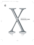
BT49QT-21B1 MODEL
SERVICE MANUAL
:
BT49QT-21B1 MODEL SPARE PARTS NAME:
CONTENTS
SUMMARY
CHAPTER ONE
Ⅰ.
1
MAINTENANCE OF THE MOTORCYCLE
ITEMS OF MAINTENANCE
2
Ⅱ. PERIODIC MAINTENANCE SCHEDULE AND MAINTENANCE LOCATIONS
2
Ⅲ.
5
MAINTENANCE SPECIFICATIONS
Ⅳ. THROTTLE ACTUATION INSPECTION
6
Ⅴ. AIR FILTER INSPECTION AND CLEANING
7
Ⅵ. BRAKE BLOCKS INSPECTION
7
Ⅶ. BRAKE SYSTEM INSPECTION, ADJUSTMENT AND REPLACEMENT
8
Ⅷ. FRONT AND REAR SHOCK ABSORBER INSPECTION
9
Ⅸ. FRONT WHEEL AND REAR WHEEL INSPECTION
10
Ⅹ.
11
STEERING STEM INSPECTION
CHAPTER TWO
MAINTENANCE INFORMATION
Ⅰ. FRAME NUMBER AND ENGINE NUMBER LOCATION
12
Ⅱ.
PRECAUTIONS IN OPERATION
12
Ⅲ.
SPECIFIED TORQUES
13
CHAPTER THREE BODY TROUBLESHOOTING
SECTION ONE BODY COMMON TROUBLES AND TROUBLE DETECTION
15
SECTION TWO DETAILED DESCRIPTIONS OF BODY PARTS TROUBLES
Ⅰ.
FRONT WHEEL SE RVICE
18
Ⅱ. FRONT BRAKE SERVICE ( DISK BRAKE )
20
Ⅲ.
FRONT SHOCK ABSORBER SERVICE
23
Ⅳ.
FRONT FORK SERVICE
23
Ⅴ.
HANDLE BAR SE RVICE
25
Ⅵ.
REAR WHEEL SERVICE
26
Ⅶ.
REAR BRAKE SERVICE
27
Ⅷ.
REAR SHOCK ABSORBER SERVICE
28
SUMMARY
This 2-stroke scooter BT49QT-21B1 is with low weight, enough power, low oil
consumption and good operating performance.
This manual is for maintenance men to repair and maintain BT49QT-21B1 and it is
also useful when maintain other models.
This manual holds the latest technical information. We reserve the right to amend the
data, instructions and specifications without advice.
The technical specifications of BT49QT-21B1:
Size and weight:
Length×width×height
1940×720×1150
Unloading weight
100kg
Wheel space
1300
Max. mass
254 kg
Fuel tank capacity
4.5±0.5L
Max. speed
45Km/h
Front tire pressure
Rear tire pressure
225KPa
225KPa
Engine:
Type
139QMA-A
Lubricate method
Pressure spray
Stroke
4
Lubricant brand
SAE15W/40SF
Cylinder diameter ×driving
distance
39mm×41.4mm
Gasoline brand
90# or above
Cylinder capacity
49cm3
Clutch type
Automatic acentric
Compression ratio
10.7±0.1:1
Transmission type
Nonpolar
3.88/6500
Starting method
Electric/kick starting
3.15/8500
Ignition method
CDI
1900±100
Cooling system
Forced air-cooled
Max torque:
N.m/(r/min)
Max power output:
kw/(r/min)
Idling speed: r/min
Electric system:
Battery
12V 6AH
Turning signal light
10W,12V
Headlight
35/35W,12V
Position light
5W,12V
Taillight/brake light
5/21W,12V
Fuse specification
10A
1
CHAPTER ONE
MAINTENANCE OF THE MOTORCYCLE
Ⅰ. ITEMS OF MAINTENANCE
When the motorcycle is used, parts loose and mechanical wear inevitably occur to
varied extents. Neglecting of timely maintenance not only reduces its mechanical
function, economic performance, stability and durability, but also threatens the safety
of the motorcycle and the rider. Correct and timely maintenance of the motorcycle is
necessary. Items of maintenance refer to the parts and positions for maintenance.
Different items of maintenance are affected in different intervals and in different
manners.
1. Running-in Maintenance
This is the maintenance at the end of the first 1000km and is an all-round inspection
of motorcycle. A newly-bought motorcycle or a motorcycle fresh from an overhaul
might be severely overheated as a result of severe friction between the moving parts
which might be imperfect in finishing or fitting. Neglecting in use might lead to
damage of the friction surfaces and might threaten the performance, and the service
life of the motorcycle. Please observe the following points:
Restrict the speed in speed range specified in the instruction manual.
Restrict the load to 2/3 of the maximum load and ride in fairly good road
conditions.
Restrict the length of riding time to avoid long-time running of the engine.
Replace engine oil at short intervals so that metal chips caused in the runningin period can be discharged. It is recommended to replace engine oil for 3 times
during the running-in period.
2. Routine Maintenance
Routine maintenance is the basis of all kinds of maintenances. It refers to the daily
maintenance, including cleaning, inspecting and common troubleshooting.
3. Periodic Maintenance
This maintenance is to restore normal performance of the motorcycle. The
maintenance is classified into first-grade periodic technical maintenance and secondgrade periodic technical maintenance (also known as items of maintenance) according
to different mileages. Generally speaking, a first-grade maintenance is effected after
the initial 4000km and a second-grade maintenance is effected every 8000km. As the
service time extends, maintenance intervals should be shortened accordingly.
Ⅱ. PERIODIC MAINTENANCE SCHEDULE AND MAINTENANCE LOCATIONS
After a period of using (one day, one month or half a year, for example) or a certain
mileage (1000km, 4000km, 8000km, for example), an all-round maintenance
operation should be effected, including comprehensive inspection, adjustment,
tightening, lubrication, cleaning or replacement. The specific regulation made
according to time intervals or mileages is known as maintenance interval. The
motorcycle maintenance schedule is as follows.
2
1. Maintenance Schedule
Maintenance Schedule
time
item
Mileage 1000km
Engine oil
1000
2000
3000
4000
5000
6000
7000
8000
9000
10000
11000
12000
New R
300km
R
R
R
R
R
R
R
R
R
R
R
Engine oil
strainer
C
C
Gasoline
strainer
Gear oil
R
Note 4
New R
300km
Throttle play
R
A
Carburetor
Air filter
Note 3,
4
A
A
A
I
I
C
I
R
Spark plug
Brake system
R
R
Clean every 3000km, replace when necessary
I
I
I
I
I
I
Drive belt
I
I
I
I
I
I
I
Suspension
I
I
I
Tire
I
I
I
Steering rod
bearing
I
Screws and
bolts of parts
I
I
I
I
Rear brake
cam
C
Notes:
1. I: Inspect and when necessary, clean, lubricate, supplement, modify or replace.
A: adjust; C: clean; R: replace; T: tighten.
2. Effect periodic maintenance according to the instructions in the user’s manual.
3. When the mileage exceeds the range specified in the schedule, repeat the
maintenance.
4. In dusty or rainy conditions, inspection and replacement should be effected
earlier.
5.
In heavy load, long distance or rainy conditions, replacement should be
effected earlier.
3
2. Maintenance locations
4
Ⅲ. MAINTENANCE SPECIFICATIONS
The basic methods of motorcycle maintenance include inspection, adjustment,
tightening, lubrication, cleaning, supplementing and replacement, which constitute the
main elements of maintenance.
1. Inspection
Inspection refers to basic inspecting operations in accordance with items and
requirements specified in the user’s manual, including inspection with
instruments or with eyes for abnormalities in machine parts, directly
comparing related data and aligning with tools and gauges.
2. Adjustment
Adjustment refers to inspection-based adjustment and rectification of some
specified machine parts, including adjustment of machine part plays and
rectification of misfittings and deformations so as to restore correct positions,
forms and plays.
3. Tightening
Tightening refers tightening of bolts, screws and nuts of machine parts with
tools so as to avoid loosening of machine parts and to obtain specified
tightening torques.
4. Cleaning
Cleaning is needed where call for cleanliness and tidiness. Cleaning
operations include all the means and measures taken to remove dust,
contamination, metal chips, oily stains and carbon deposits that might lead to
pipe clogging or reduction in motorcycle performance. Cleaning measures are
washing, carbon deposit removing, rubbing, cleaning and clearing.
5. Lubrication
In order to facilitate smooth and easy running of moving machine parts,
including swinging parts, reciprocating parts, sliding parts and vibrating parts,
to reduce scuffing, abrasion, deformation and to reduce friction, it is
necessary to coat or spray these parts with a lubricant. Different lubricants
and lubricating methods are required for different machine parts with
different functions. Application of lubricants to machine parts is known as
lubrication.
6. Replenishing, supplement and replacement
These operations refer to addition of oil, lubricants, cooling water, electrolyte,
fuel and replacement of damaged parts with new ones and replacement of
denatured oils with new oils.
5
IV. THROTTLE ACTUATION INSPECTION
Inspect throttle grip for easy and smooth
movement.
Inspect throttle free travel.
Free travel: 2-6mm
The main adjusting position is beside the
carburetor.
Remove rear luggage box cover.
Adjust by loosening the fastening nut and
turning the adjusting nut.
Fine adjustment is effected on the side of
the throttle grip.
Effected adjustment is by removing the
dust cover, loosening the tightening nut and
turning the adjusting nut.
6
Ⅴ. AIR FILTER INSPECTION AND CLEANING
After a certain mileage, dust and impurities will gather in air filter case and strainer,
which will clog strainer pores and reduce inlet of air and thus lead to excessive
concentration of mixed gas and reduce the performance of engine. That’s why the
strainer must be cleaned every 2000-3000km and in dusty or rainy conditions strainer
must be cleaned or replaced earlier.
Remove 5 tightening screws of air filter.
Remove strainer cover.
Take out the foam strainer.
Immerse foam strainer in gasoline and
wash it to remove dust and impurities by
gripping and pressing.
Press gasoline out of the foam.
Soak the cleaned foam with engine oil,
press out or throw out engine oil to leave it
moist with oil.
Mount.
VI. BRAKE BLOCKS INSPECTION
cleaning
gripping
gasoline soaking
gripping
¢ Û
Grip the brake lever and check the wear
& tear indicator on the brake blocks. If the
indicator nearly touched brake disc, the
brake blocks must be replaced with new
¢ Ù
¢ Ú
¢ Ù--- wear & tear indicator
¢ Ú--- brake disc
¢ Û--- brake blocks
ones.
7
VII. BRAKE SYSTEM INSPECTION, ADJUSTMENT AND REPLACEMENT
1. Front brake (disk brake)
Remove the bolts linking brake caliper
and front shock absorber.
Remove brake caliper.
* Do not pull brake lever when brake
caliper is removed so as to prevent jamming
of brake block.
If brake block is jammed, pry it with
screwdriver and push piston back into
caliper.
Brake Block Replacement:
Brake block must be replaced when it is
worn to the limit of use.
* It is not necessary to remove brake oil
pipe when replacing brake block.
* Brake block must be replaced as a set.
Remove the brake block pins.
Take out the old brake blocks and mount
a set of new brake blocks.
Effect mounting in an order reversed to
that of dismounting.
Brake Disc Inspection:
Inspect brake disc thickness.
Limit of use: 3.0mm
Inspect brake disc angularity.
Limit of use: 0.3mm
8
2. Rear Brake
Inspect rear brake lever free travel.
Free travel: 10-20mm
Turn adjusting nut to effect adjustment
when free travel exceeds limit.
VIII. FRONT AND REAR SHOCK ABSORBER INSPECTION
1. Front Shock Absorber
Tighten front brake lever, press front
shock absorber up and down and inspect
actuation.
Inspect front shock absorber to see if
there is leakage of oil and if there is damage
or loosening.
2. Rear Shock Absorber
Press rear shock absorber to inspect
actuation. Inspect rear shock absorber to see
if there is oil leakage and if there is damage
or loosening in machine parts.
Lift rear wheel, press rear wheel right and
left to inspect if engine suspension lug
buffer bush is loose.
9
IX. FRONT WHEEL AND REAR WHEEL INSPECTION
Wheel Rim Inspection:
Inspect wheel rim, remove rust stains and rubber chips.
Deformation and fissures are causes of air leakage. Do not use wheel rims in the
following cases:
Bruise of wheel rim face contacting tire bead ring exceeds 0.5mm in depth and
1.0mm in width.
Tire Inspection:
Inspect if there is fissure or iron nail in the tire.
In one of the following conditions, tires must be replaced instead of repair.
Puncture of tire by a foreigner matter 6mm in diameter or tire fissure.
Layered tire.
Chunking of tread
Damaged tire bead
Broken tire bead or other tire bead damages
Broken tire cord
Damage due to forced dismounting
Fissure extending to frame
Abnormal inner lining
Tire groove wear: front wheel < 0.8mm, rear wheel < 0.8mm.
Punctured or otherwise damaged tire flank
Inspect tire pressure by means of a tire pressure gauge
* Tire pressure should be inspected when the motorcycle is in a cold state.
Specified pressure
Unit: kPa
Front wheel
225
Rear wheel
225
Tire Specifications:
Front wheel
110/70-12
Rear wheel
110/70-12
10
Inspect if front wheel nut is loose.
Inspect if rear wheel nut is loose.
If loose, tighten them to specified torques.
Torques: front wheel nut 60N·m
rear wheel nut 120N·m
X. STEERING STEM INSPECTION
Swing handlebar right and left to see if
there is interference such as wire or other
things.
Turn front wheel to see that handlebar is
easy in operation.
In case of any difficulty in operation,
inspect steering stem bearing assembly.
11
CHAPTER TWO
MAINTENANCE INFORMATION
I. FRAME NUMBER AND ENGINE NUMBER LOCATION
II. PRECAUTIONS IN OPERATION
Removed washers, 0-rings, elastic retaining rings and split pins must be
replaced with new ones.
When mounting bolts, nuts and screws, proceed from trial tightening, from
larger diameters to smaller diameters and inner ones to outer ones in a
diagonally order. Tighten them to specific torques.
Parts and greases must be those made by our factory or recommended by our
factory.
Special operations must be effected with special tools or specified universal
tools.
Removed parts must be rubbed or cleaned before they are inspected or
measured. They must be coated on the sliding faces before mounting.
They must be greased at the specified positions with designated or equivalent
greases.
Parts must be tightened and their performances inspected at their positions
when mounted.
The battery’s negative terminal must be disconnected before operation.
Make sure that tools such as wrenches are not in contact with the frame.
At the completion of operations, reconfirm correct connections and fastenings.
The positive terminal must be connected first in case of a removed battery.
Connected terminals must be coated with lubricant.
The terminals must be completely covered with caps.
When a fuse is burnt, inspect the cause and replace the fuse with a fuse of
equivalent capacity.
At the completion of operation, completely cover terminals with caps.
When removing connectors with locks, they must be unlocked before operation.
When removing connectors, the connectors proper must be held instead of
pulling their wires.
Before connecting connectors, confirm that they are free from breakage,
bending, over length or loosening.
12
Connectors must be inserted home.
When connecting connectors with locks, confirm that their locks are fastened.
Confirm that the wires are not loose.
Confirm that connectors’ plastic sleeves completely cover the connectors
without fail.
Before connecting the connectors, confirm that their sleeves are free from
breakage and their terminals are not oversized.
Connector plugs must be fully inserted.
Confirm that plastic sleeves completely cover the terminals.
Plastic sleeves should not be placed with the open side up.
Wire bunch bands should be fixed at the specified position of motorcycle frame.
Wire clamps must correctly keep wires in place.
Avoid welding stains of welded clamps when clamping wires.
Wire bunches must be fixed away from turning or moving parts.
Do not damage the covering of wire bunches.
In case of wire bunch defects, remedy it with insulating bands.
Wire bunches must not be covered with mounted parts.
Do not twist or bend cables by force. Deformed or damaged cables would
result in poor rotation or damage.
Ⅲ. SPECIFIED TORQUES
Torques at important positions and standard torques of other positions are as
follows:
SPECIFIED TORQUES
Frame:
Number
Thread
specification
Torques:
N·m
Engine suspension lug mounting nut
1
M10
45
Engine mounting nut
1
M10
45
Front axle nut
1
M12
60
Rear axle nut
1
M16
120
Rear shock absorber upper mounting bolt
1
M10
40
Rear shock absorber lower mounting bolt
1
M8
25
Front shock absorber upper lock bolt
2
M10
40
Steering stem lock nut
1
M25
70
Handlebar mounting nut
1
M10
45
Upper bearing top
1
M25
2.5
Exhaust muffler connector nut
2
M6
12
Exhaust muffler mounting bolt
2
M8
35
Designations of tightening positions
13
Standard Torques:
Designations
Torques: N·m
Bolt, nut M5
5
Bolt, nut M6
10
Bolt, nutM8
21.5
Bolt, nut M10
35
Bolt, nut M12
55
Screw M5
4
Screw M6
9
Flange bolt, nut M6
12
Flange bolt, nut M8
27
Flange bolt, nut M10
40
14
CHAPTER THREE
SECTION ONE
BODY TROUBLESHOOTING
BODY COMMON TROUBLES AND TROUBLE DETECTION
Body part common troubles and possible causes are as follows:
Troubles
Causes
Details (reference)
Handlebar rotation Over tightening of handlebar
not easy (strenuous adjusting nut
Refer to “Front Fork
Service”
turning or unstable Steering stem over worn
tightness)
Refer to “Handlebar
Incorrect mounting of brake cable or
Service”, “Front
tachometer cable
Fork Service”
Remarkable deformation of steering
stem due to outside impact
Refer to “Front Fork
Heavy steering stem Over tightening of steering stem top
Service”
turning
ball bearing retainer
Damaged or broken ball bearing
Refer to “Front
Wheel Service”,
Reduced tire air
“Rear Wheel
Service”
Refer
to “Front
Imbalance of right and left shock
Shock Absorber
absorbers
Service”
Deflected steering
Refer to “Front Fork
Bent front fork
stem
Service”
Refer to “Front
Bent front tire, deflected tire
Wheel Service”
Normal wear of brake lining
Hardened brake block or dusty block
Refer to “Brake
Excessive front brake and rear brake
System Inspection,
Drum brake failure Damaged brake cable
Adjustment and
Replacement”, “Rear
Brake cam rotation not easy
Brake Service”
Worn brake block
Worn or slotted brake drum bore
Disk brake failure
Feeble brake
lever
Bent brake lever
Air in hydraulic
device
Leakage in hydraulic
device
Clogged hydraulic
passage
15
Refer to “Brake
System Inspection,
Adjustment and
Replacement”,
“Front Brake
Service”
Chart continued
Troubles
Disk brake failure
Causes
Inadequate liquid
Contaminated brake
block and brake disc
Bent or deformed
brake disc
Contaminated brake
caliper
Worn seal ring of
brake caliper piston
Feeble brake Viscous or worn
lever
brake caliper piston
Inability of brake
caliper normal
sliding
Worn main cylinder
piston seal ring
Viscous or worn
main cylinder piston
Contaminated main
cylinder
Clogged narrow
brake system
Clogged narrow
liquid passage
Viscous worn brake
caliper
Stiff brake
Inability of brake
lever
caliper normal
sliding
Worn seal ring of
brake caliper piston
Viscous or worn
main cylinder piston
Contaminated brake
block and brake disc
Bent or deformed
brake disc
Resisted
Inability of brake
braking
caliper normal
sliding
Wheel not adjusted
straight
16
Details (reference)
Refer to “Brake
System Inspection,
Adjustment and
Replacement”,
“Front Brake
Service”
Chart continued
Troubles
Abnormal braking
sound
Causes
Hardened brake block surface or
dusty block
Uneven or slotted brake block
surface
Serious wear of brake block lining
Serious slots inside brake drum
Steering stem rotation not easy
Bent shock absorber
Deviation of
motorcycle direction
(inclining to roadside)
Shock absorber oil leakage
Bent front axle, incorrect wheel
mounting
Roundness error of wheel rim
Deformation of wheel rim
Inadequate tire pressure
Deformed wheel rim
Loose front wheel bearing
Front wheel oscillation Poor tire
Details (reference)
Refer to “Rear Brake
Service”
Refer to “Front Fork
Service”
Refer to “Front Shock
Absorber Service”
Refer to “Front Wheel
Service”
Refer to “Front Wheel
Service”
Poor axle locking
Soft front shock
absorber
Rear wheel oscillation
Soft rear shock
absorber
Spring fatigue
Refer to “Front Shock
Absorber Service”
Deformed wheel rim
Poor wheel
Refer to “Rear Wheel
Service”
Spring fatigue
Refer to “Rear Shock
Absorber Service”
17
SECTION TWO
DETAILED DESCRIPTION OF BODY PARTS MALFUNCTION
Precautions in Operation:
Forced mounting or dismounting of body cover parts will cause damage to claws
and slots of corresponding hoods.
When mounting body cover parts, be sure to align the corresponding parts of
hoods.
When mounting body cover parts, avoid pressing wires, cables or pipes.
I. FRONT WHEEL SERVICE
Front Wheel Dismounting:
Support the body bottom to lift front wheel.
Remove the connecting bolts linking brake
calipers and front absorber, remove brake
calipers; loosen axle nut, remove the front
axle nut, front shock absorber, transmission
gearbox, front axle bush and the small bush,
remove front axle.
Remove front wheel.
Remove brake disc mounting bolts.
Remove brake disc.
18
Axle Bending Inspection
Place axle on a V-seat and measure with a
dial gauge.
The dial gauge indicates a 1/2 bending value.
Limit of use: Replace if >0.2mm.
Wheel Rim Oscillation Inspection
Measure oscillation value on a correcting bench.
Limit of use: Replace if >2.0mm.
Traverse direction: Replace if >2.0mm.
Front Wheel Bearing Inspection
Remove front wheel bearing and dust cover.
Turn bearing inner race to inspect sliding.
Replace it with a new one in case of no
sliding or damage or loosening of outer race.
19
Front Wheel Bearing Replacement
Dismounting: Remove front wheel bearing by means of a bearing remover, take out
spacer.
Mounting: Apply grease to the bearing.
Drive in left bearings.
Mount spacer.
Drive in right bearings.
Bearings must be driven in parallel.
Dust cover must be driven in with the face out.
Apply grease to new dust cover lip.
Mount front axle bush.
Front Wheel Mounting
Mount brake disc, tighten brake disc mounting bolts.
Torque: 27N·m
Spread front axle with a thin film of grease.
Mount front axle from left side.
Mount in order small bush, left front shock absorber, bush, front wheel, transmission
gearbox, right front shock absorber, front axle nut and fasten it.
Torque: 60N·m
Mount brake caliper as specified.
II. FRONT BRAKE SERVICE (DISK BRAKE)
Brake Oil Replacing
Prevent dust or water from entering brake system.
Do not use brake oils of different specifications or impure brake oils.
Prevent brake oil from dripping onto rubber, plastic or painted parts.
Brake Oil Exhausting
Place main cylinder at a level place, remove
oil reservoir cover and diaphragm.
Connect a hose to oil exhaust valve, loosen
exhaust valve, grip and release brake lever
till oil is exhausted.
20
Brake Oil Replenishing
Lock exhaust valve.
Replenish oil reservoir with specified brake
oil.
·It is not necessary to fill the oil reservoir
to the full capacity.
·Brake oil for replenishing should be the
same as original.
The specification of brake oil is indicated on
the reservoir cover.
Place diaphragm.
Connect a transparent hose to exhaust valve.
Grip brake lever fast and open exhaust valve
1/2 turn to let out air and lock exhaust valve.
Repeat this operation till no bubbles are
exhausted from brake oil passage.
·Do not release brake lever before exhaust
valve is closed.
At the completion of adjustment, replenish
brake oil till oil is over the lower limit line
of the oil reservoir.
Mount diaphragm set and oil reservoir cover.
Tighten oil reservoir cover bolt.
Main Brake Oil Tank Dismounting and Mounting
Dismounting
Remove screws of front part and rear part of
head cover.
Remove front part and rear part of head cover.
21
Exhaust brake oil from front brake system.
Pull out brake switch plug from main cable.
Remove bracket bolts from handlebar,
Remove main cylinder.
Remove brake oil pipe from main cylinder.
· Prevent brake oil from splashing to
rubber, plastic or painted surfaces. Cover
the above-mentioned parts with a cloth.
Remove brake light switch and brake lever.
Remove retaining ring from main cylinder.
·Use special retaining ring remover when removing retaining ring.
Remove piston cover, piston and spring.
Clean oil reservoir and piston with pure brake oil.
·Do not effect cleaning with gasoline as it is corrosive to rubber parts.
Inspection
Inspect for wear or ageing of main and auxiliary cups on pistons.
Inspect for scratches and other damages on main cylinder and piston.
Measure main cylinder bore.
Measure outside diameter of piston at the end of auxiliary cup.
Mounting
Apply pure brake oil to piston, main cup and auxiliary cup.
Mount spring, piston, retaining ring and piston cap.
·Piston cup cannot be used inside out.
Apply grease to brake lever axis pin.
Mount brake lever and brake switch.
Mount main cylinder, main cylinder bracket and lock them.
Mount brake oil pipe.
Connect brake light switch cable with switch.
Mount head cover front part and rear part.
Replenish brake oil and exhaust air in brake system.
22
Ⅲ. FRONT SHOCK ABSORBER SERVICE
Dismounting
Remove front body covering parts.
Remove front brake calliper.
Remove front wheel.
Remove front fender mounting bolts and
front fender mounting bracket.
Remove front fender.
Remove 2 pieces of bolts on the upper part
of front shock absorber.
Remove shock absorber.
Inspection
Inspect if there is oil leakage in front shock
absorber, if there is deformation of shock
absorber arm and if there is damage or
loosening of any part.
Mounting
Mount front shock absorber on front fork
and mount 2 bolts.
Torque: upper bolt 40N·m.
Mount front body covering parts.
Mount front fender mounting bracket .
Mount front fender.
Mount front wheel.
Ⅳ. FRONT FORK SERVICE
Dismounting
Remove front body covering parts.
Remove bolt, bush and nut.
Remove handlebar.
Remove steering stem set nut.
Remove upper bearing cup, upper bearing
top and bearing set.
23
Remove front wheel and front shock
absorber together with front fender and
steering stem from head tube.
The removing of the bottom bearing cup,
bearing top and bearing set is the same as
the removing of the upper series.
Do not damage steering stem when
removing bearing cup and bearing top.
Clean opening parts of motorcycle
body covering parts with cloth.
Inspection
Inspect if there is slot or pit in bearing cup
and bearing top. If there is, effect
replacement.
upper bearing top
upper bear ing cup
bottom bearing top
Inspect for completeness of bearing balls
and if there is, effect replacement with new
ones.
Inspect for proper tightness of steering stem
and if not, effect adjustment and fasten it.
Inspect for correct position of bearing cup
and bearing top and if not, effect correct
mounting.
bottom bearing cup
ball set
ball set
Bearing Cup and Bearing Top Replacement
Remove bearing cup and bearing top with special bearing cup and bearing top
removers.
Mounting
Apply grease to bearing cup and bearing top at the bottom.
Mount in order bottom bearing cup, bearing ball set, bottom bearing top on the bottom
of steering stem.
24
Pass steering stem through head tube.
Apply grease to top bearing cup and bearing top.
Mount in order upper bearing cup, bearing ball set and upper bearing top on the upper
part of steering stem and fasten them.
Torque: 15 N·m
Turn front fork right and left to effect close contact of bearing balls.
Loosen upper bearing top to torque 0 and fasten it.
Torque: 2.5N·m
Fix upper bearing top and tighten steering stem setting nut.
Torque: 70N·m
Turn front fork and confirm easy rotation without loosening.
Lock set nut.
Mount handlebar bolt, bush and nut.
Mount handlebar.
Mount front body covering parts.
Ⅴ.
HANDLEBAR SERVICE
Dismounting
Remove covering parts of front part and rear
part.
Remove left brake lever.
Remove left grip from handlebar.
Remove front brake main cylinder.
Remove throttle cable and throttle cable seat.
Remove throttle grip from handlebar.
Remove handlebar bolt, bush and nut from
handlebar.
Remove handlebar.
25
·When removing left grip and throttle grip, remove contamination and grease from
contacting face.
Mounting
Mount handlebar on steering stem guide tube, fit bush, setting bolt and nut.
Torque: 45 N·m
Mount left brake lever and fasten bolts.
Torque: 9 N·m
Mount front brake main cylinder.
Apply grease to throttle cable.
Mount throttle cable seat and connect throttle cable.
Mount throttle grip.
Mount covering parts of front head cover and rear head cover.
Confirm easy rotation of throttle grip.
When mounting handlebar rubber, apply a thin film of adhesive to contacting
face and then mount grip in a turning manner.
Ⅵ. REAR WHEEL SERVICE
Dismounting
Remove 2 connecting nuts and 2 mounting
bolts of exhaust muffler.
Remove exhaust muffler.
Remove rear axle nut.
Rear Wheel Oscillation Inspection
Measure oscillation value on a correcting
bench by means of micrometers.
Limit of use: Longitudinal >2.0 mm
Traverse >2.0 mm
26
Mounting
Mount rear wheel and fasten rear axle nut.
Torque: 120N·m
Mount exhaust muffler.
Fasten exhaust muffler connecting nuts and bolts.
Torque:
Exhaust muffler connecting nut: 12N·m
Exhaust muffler mounting bolt: 35N·m
Ⅶ. REAR BRAKE SERVICE
Remove exhaust muffler.
Remove rear wheel.
Inspect rear brake drum.
Measure rear brake drum bore.
Limit of use: Ø111mm, effect replacement if
the limit is exceeded.
Rear Brake Block Replacement
Remove rear brake block and return spring
as a whole and replace them with new ones.
· See that no grease is with brake block
friction surface.
set pin
return spring
brake block
return spring
brake block
brake cam
Rear Brake Disassembling
Remove rear brake adjusting nut, remove
rear brake cable from brake swing arm.
Remove brake block assembly.
Remove brake swing arm setting bolt
and swing arm.
brake cam
set bolt
brake swing arm
rear brake cable
Remove brake cam.
Rear Brake Device Assembling
Apply grease to setting pin, brake cam and brake block friction surface.
Apply grease to moving part of brake cam.
27
adjusting nut
Do not apply grease to parts not specified. Superfluous grease flows into brake
friction linings of brake drum shall reduce braking effect.
Mount brake cam.
Mount brake swing arm on brake cam.
Notch on brake swing arm should be aligned with the cut-off of brake cam.
Mount brake swing arm setting bolt and
fasten it.
Torque: 10N·m
Mount brake block assembled with spring.
Mount rear wheel.
Mount exhaust muffler.
Mount brake swing arm pin and rear brake
cable.
·Mount return spring of brake cable with
the spring aligned with the recess hole
of left crankcase cover.
Mount adjusting nut.
Adjust brake system.
Ⅷ.
REAR SHOCK ABSORBER SERVICE
Dismounting
Remove motorcycle body covering parts.
Remove 3 mounting bolts of air filter.
Withdraw air filter.
Remove mounting bolt connecting rear
shock absorber and motorcycle frame, bolt
connecting rear shock absorber and engine.
Remove rear shock absorber.
28
adjusting nut
return spring
rear brake cable
Inspection
Inspect rear shock absorber oil seal for oil
leakage, inspect buffer bar and spring for
deformation and other parts for damage and
loosening.
Mounting
Mount rear shock absorber.
Torque:
upper mounting bolt: 40N·m
bottom mounting bolt: 25N·m
Mount air filter.
Mount motorcycle body covering parts.
29