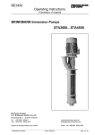
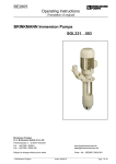
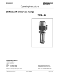
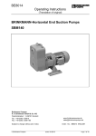
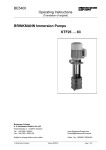
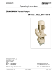
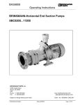
1
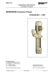
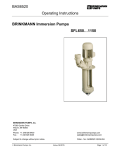
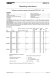
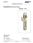
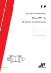
BAS6085_a Operating Instructions BRINKMANN Cutter pumps SFC820…1160 BRINKMANN PUMPS, Inc. 47060 Cartier Drive Wixom, MI 48393 USA Phone: +1 248 926 9400 Fax.: +1 248 926 9405 www.brinkmannpumps.com [email protected] Subject to change without prior notice. Brinkmann Pumps, Inc. Order - No.: BAS6085_a ENGLISH Edition 04/2015 Page 1 of 10 Brinkmann Cutter pumps of the series SFC820…1160 Contents 1 2 3 4 5 6 7 Indication to the manual .................................... 2 Description of the Product .............................. 2-3 Safety instructions ............................................. 4 Transportation and Storage ............................... 4 Installation and Connection ............................... 5 Start-up / Shut-down ......................................... 6 Operation........................................................... 6 8 9 10 11 12 13 1 Indication to the manual This operating manual gives basic instructions which are to be observed during installation, operation and maintenance of the pump. It is therefore imperative that this manual be read by the responsible personnel and operator prior to assembly and commissioning. It is always to be kept available at the installation site. 1.1 Identification of safety instructions in the operating manual Safety instructions given in this manual noncompliance with which would affect safety are identified by the following symbol Servicing and Maintenance ............................... 6 Troubleshooting Guide ...................................... 7 Spare Parts..................................................... 8-9 Repair ................................................................ 9 Disposal ............................................................. 9 WARRANTY .................................................... 10 2.2 Intended use The cutter pumps SFC are suited for cutting aluminum chips or similar materials and for pumping these materials along with the coolant fluid. An agitator located at the pump suction helps to break up and separate any large bundles of chips or birds’ nests which reach the pump suction. Pay attention of the limit of application in table 1! Limit of Application (Table 1) Type SFC Mediums Coolant, cooling- and cutting-oils Chip material Aluminium, steel, coloured steels max. chip to coolant ratio by weight: 1.5% Safety sign according with ISO 3864 – B.3.1 or where electrical safety is involved, with: Chip geometry Chip bundles to max. Ø 3.9 Inch (100 mm) Safety sign according with ISO 3864 – B.3.6 Where non-compliance with the safety instructions may cause a risk to the machine and it’s function the word Kinetic viscosity …200 SSU (...45 mm2/s) of the medium Temperature of medium 30 … 175 °F (0 ... 80 °C) Dry running Dry running causes increased wear and should be avoided. During the test of the direction of rotation (< 30 s) permissible. Motor cycle time per hour The pump SFC should be operated in continual operation mode, not pulsed mode. Ambient temperature 104 °F (40 °C) Set-up altitude 3280 ft (1000 m) ATTENTION is inserted. 2 Description of the Product 2.1 General description of the pump Pumps of the series SFC are one-stage rotary pumps. The impellers are fixed on the driving shaft extension. The pump shaft and motor shaft are interconnected by means of a shaft clamp. The cutting unit is cutting the chips and the semi-open impeller with its large clearances allows to pump the particles along with the coolant fluid from the machine back to the filter. The SFC pumps are capable of handling chip to coolant ratios of up to 1.5% by weight. Pump and motor form a compact and spacesaving unit. Vertically mounted pumps are equipped with a mounting flange. The pump end immerses into the tank and the motor extends vertically above the tank. BAS6085_a ATTENTION The pumps are to be operated within their design limits. Applications outside of these limits are not approved. The manufacturer is not responsible for any damages resulting from use of the pumps in such applications. Edition 04/2015 Page 2 of 10 2.3 Technical data Max. del. pressure spec. weight 1 PSI bar Max. del. volume SFC820S 290 390 520 640 24 1.7 250 1000 19.2 SFC1120S 290 390 520 640 30 2.0 310 SFC1160S 290 390 520 640 44 3.0 400 Type GPM Height Depth of immersion h Inches mm Weight 487 11.50 15.43 20.55 25.28 292 392 522 642 152 157 161 168 1200 19.8 504 11.50 15.43 20.55 25.28 292 392 522 642 1600 24.1 611 11.50 15.43 20.55 25.28 292 392 522 642 H Inches mm l/min lbs Power kg HP kW 69 71 73 76 5.4 4.0 201 205 209 216 91 93 95 98 7.4 5.5 254 258 262 269 115 117 119 122 13.8 10.3 The motor is surface-cooled and compliant with DIN IEC 34 and EN 60034 (protection degree IP 55). BAS6085_a Edition 04/2015 Page 3 of 10 3 Safety instructions When operating the pump, the safety instructions contained in this manual, the relevant national accident prevention regulations and any other service and safety instructions issued by the plant operator are to be observed. 3.1 Hazards in the event of non-compliance with the safety instructions Non-compliance with the safety instructions may produce a risk to the personnel as well as to the environment and the machine and results in a loss of any right to claim damages. For example, non-compliance may involve the following hazards: Failure of important chines/plant functions of the ma- Failure of specified procedures of maintenance and repair Exposure of people to electrical, mechanical and chemical hazards Endangering the environment due to hazardous substances being released 3.2 Unauthorized modes of operation Pump may not be used in potentially explosive environments! Pump and discharge piping are not designed to hold any weight and may not be used as a step ladder. 3.3 3.5 Safety instructions relevant for operation If hot or cold machine components involve hazards, they must be guarded against accidental contact. Guards for moving parts (e.g. coupling) must not be removed from the machine while in operation. Any leakage of hazardous (e.g. explosive, toxic, hot) fluids (e.g. from the shaft seal) must be drained away so as to prevent any risk to persons or the environment. Statutory regulations are to be complied with. Hazards resulting from electricity are to be prevented (see for example, the VDE Specifications and the bye-laws of the local power supply utilities). The pumps’ stability against falling over is not ensured unless it is properly mounted onto the tank. The female threads on the motor MUST NOT be used to lift the entire pump and motor assembly. 3.6 Safety instructions relevant for maintenance, inspection and assembly work Any work on the machine shall only be performed when it is at a standstill, it being imperative that the procedure for shutting down the machine described in this manual be followed. Pumps and pump units which convey hazardous media must be decontaminated. On completion of work all safety and protective facilities must be re-installed and made operative again. Prior to restarting the machine, the instructions listed under “Start up” are to be observed. 3.7 Signs on the pump It is imperative that signs affixed to the machine, e.g.: arrow indicating the direction of rotation symbols indicating fluid connections be observed and kept legible. Remaining Risk 3.8 Risk of Injury! Risk of squeezing or crushing body parts when installing or removing the pump exists. Proper and secured lifting tools must be used. Risk of burns! The pump must have cooled down sufficiently prior to commencing any repair, maintenance or installation. 3.4 Qualification and training of operating personnel The personnel responsible for operation, maintenance, inspection and assembly must be adequately qualified. Scope of responsibility and supervision of the personnel must be exactly defined by the plant operator. If the staff does not have the necessary knowledge, they must be trained and instructed, which may be performed by the machine manufacturer or supplier on behalf of the plant operator. Moreover, the plant operator is to make sure that the contents of the operating manual are fully understood by the personnel. BAS6085_a Unauthorized alterations and production of spare parts Any modification may be made to the machine only after consultation with the manufacturer. Using spare parts and accessories authorized by the manufacturer is in the interest of safety. Use of other parts may exempt the manufacturer from any liability. 4 Transportation and Storage Protect the pump against damage when transporting. Pump may not be placed on its pump end! Protective packaging should remain on the pump end until its installation. The pumps may only be transported in a horizontal position and hooks or straps must be attached on the motor and pump end. Do not use the pump shaft for connecting any transportation aids such as hooks or straps. Pumps must be drained prior to their storage. Store pump in dry and protected areas and protect it against penetration of foreign bodies. Always store pump above the freezing point! Edition 04/2015 Page 4 of 10 5 Installation and Connection 5.1 Mechanical installation During any assembly or disassembly process the pumps must be secured against tipping trough ropes for example at all times. Pumps must be mounted securely. Piping, tank and pumps must be mounted without any tension. The inlet is at the bottom of the immersed pump body. The bottom of the agitator must be located 3.9 Inch (100 mm) above the tank bottom in order to prevent unwanted objects, such as broken tools or indexing plates from entering the pump suction. This distance is critical and must be maintained at all times. To obtain the full flow rate it is recommended to choose for the pipework the nominal bore diameter of the pumps cross section for connection. Therefore pipe bends should be used, not pipe angles! The pipework must be qualified for occuring hydraulic pressure. As particles and/or chips can be redirected from the pump suction at a high velocity, the tank design must incorporate appropriate protection, i.e. a tank cover, that prevents such objects from being ejected out off the tank. 5.2 Electric wiring All service work must be carried out by qualified service personnel. Pump must be disconnected from the power source and all rotating parts must stand still. Reassure that pump is disconnected from power source and cannot be switched on. Verify that there is no voltage at the terminal board! According to the European Standard EN809 a motor overload must be installed and properly set to the full load amps stated on the pump name plate. It is the responsibility of the machine operator to decide whether or not an additional emergency switch must be installed. 5.2.1 Circuit Tension voltage and frequency must correspond with the shown specification on the nameplate. The pump must be wired so that a solid longterm electrical connection is ensured. Establish a solid ground connection. The electrical wiring must be performed according to the wiring diagram shown inside the terminal box cover. (Please see above sample wiring diagrams) Wiring diagram e.g. Voltage changing 1:2 YY / Y e.g. 230 / 460 V, 60 Hz Dimensions in Inches (mm) *) Dimension for SFC1120 YY Low Voltage ATTENTION Maximum tightening torque for piping connections is 130 ft. lbs. (170 Nm)! When installed the space around the pump must be large enough to provide sufficient cooling of the motor. Do not prop up the pressure line via the joining socket. The pump must be mounted in that way that rotating parts under the cover of the coolant tank can not be touched! BAS6085_a Y High Voltage There may be no foreign objects such as dirt, particles or humidity inside the terminal board. Mount terminal board cover to motor tight against dust and humidity and close up all unused wiring ports. ATTENTION When Variable Frequency Drives are used interfering signals might occur. Non-sinus shaped supply voltage from a variable frequency drive might result in elevated motor temperatures. Edition 04/2015 Page 5 of 10 6 Start-up / Shut-down 6.1 ATTENTION Start-up ATTENTION Switch off at the mains. After connection the electrical wires, close the terminal box. Briefly start the motor (max. 30 sec.) and check the rotation according to the arrow on the top of the motor. If the direction is incorrect change over two of the power leads. 6.2 The SFC pump should be operated in continual operation mode, not pulsed mode! Pulsed mode causes increased wear due to the return flow of chips and additional load on the bearings. The pump should transport medium without chips for 1-2 minutes before being switched off! Shut-down All service work must be carried out by qualified service personnel. Pump must be disconnected from the power source and all rotating parts must stand still. Reassure that pump is disconnected from power source and cannot be switched on. Verify that there is no voltage at the terminal board! Open terminal box and disconnect the power leads. Empty out the pump. 7 Operation Liquid level According to the drawing shown below, the maximum liquid level must stay about 1.18 Inch (30 mm) below the mounting flange. The pump begins to prime once the liquid level reaches the agitator. The pump suction is at the bottom of the immersed pump body. The pump draws the fluid level down to the level of the agitator. The bottom of the agitator must be located 3.9 Inch (100 mm) above the tank bottom in order to prevent unwanted objects, such as broken tools or indexing plates from entering the pump suction. This distance is critical and must be maintained at all times. Unwanted objects, such as broken tools or indexing plates which still lie under the pump after stopping the working process must be taken out in regular intervals! Any repair or maintenance work must be performed after the pump has been turned off and the shaft has come to a complete stop. Risk of injury! See provided warning label! If the pump should lock up and cease, shut pump down (see 6.2) and disconnect from power supply. Pump must be uninstalled and removed from the system prior to its repair. 8 Servicing and Maintenance ATTENTION The surface of the motor must be kept free of dirt. The motor shaft is spinning in permanently greased ball bearings (with special grease and increased bearing play) and does not require any special maintenance. max. liquid level min. liquid level min. distance to the tank bottom Dimensions in mm BAS6085_a Edition 04/2015 Page 6 of 10 9 Troubleshooting Guide Fault Cause Remedy Motor does not start, no motor noise At least two of the power supply leads have failed Check fuses, terminals and supply leads . Overload has tripped Inspect overload One of the supply leads has failed See above Impeller faulty Motor bearing faulty Replace impeller Replace bearing Overload trips Pump locked up mechanically High on/of cycling frequency Inspect pump hydraulics Check application Power consumption is too high Wrong direction of rotation of impeller Lime or other deposits mechanical friction See above High on/off cycling frequency Wrong power supply (voltage or cycles) See above Power supply must correspond with name plate rating Insufficient cooling Check air flow at motor fan Pump does not pump liquid level too low Pump mechanism faulty Pipe blocked Fill up liquid replace pump mechanism Clean pipe Insufficient flow and pressure Wrong direction of rotation of impeller Change over two power supply leads Pump mechanism silted up Worn pump mechanism Clean pump mechanism Replace pump mechanism Incorrect flow or pressure Wrong power supply (voltage or cycles) Power supply must correspond with name plate rating Running noise/Vibration Foreign objects in pump end Impeller damaged Bearing/Bushing broken Remove foreign objects Replace impeller Replace bearing/bushing Motor does not start, humming noise Motor overheats BAS6085_a Edition 04/2015 Clean pump mechanism repair pump Page 7 of 10 10 Spare Parts 10.1 Spare Part List for the Cutter Pumps of the Series SFC820…1160 Item Description 1 2 3 4 5 6 7 8 9 10 11 12 13 14 15 16 17 19 20 21 22 23 24 25 50 51 52 53 54 55 56 58 59 60 61 65 70 71 72 75 76 78 79 80 81 82 84 92 93 94 95 96 97 BAS6085_a Edition 04/2015 Stator with terminal board Motor flange End shield Terminal box 5.4 HP (4.0 kW) Terminal box frame up 7.4 HP (5.5 kW) Terminal box cover up 7.4 HP (5.5 kW) Fan Fan cover Ball bearing DIN Ball bearing DIN Gasket Gasket 7.4 HP (5.5 kW) Retaining ring Thread rolling screw DIN Socket head cap screw with lock DIN Socket head cap screw with lock DIN Socket head cap screw with lock DIN Parallel pin DIN Bearing cover Socket head cap screw DIN Shaft nut Compensation disk Shaft seal O-ring Pump body Shaft with rotor Shaft seal Intake cover Socket head cap screw with lock DIN Washer Chip breaker Socket head cap screw with lock DIN Inlet cover Socket head cap screw with lock DIN Bushing cartridge assembly Socket head cap screw with lock DIN Insert shaft Shaft clamp Splash ring Impeller Woodruff key DIN Suction screw Woodruff key DIN Shaft nut Agitator Socket head cap screw with lock DIN Serrated lock washer Joining socket Socket head cap screw DIN Spring washer DIN O-ring Screw plug DIN Sealing ring DIN 628 625 7500 912 912 912 7 912 912 7984 912 912 6888 6888 912 912 7980 908 7603 Page 8 of 10 10.2 Indications to the spare part order Spare parts are available from the supplier. Standard commercially available parts are to be purchased in accordance with the model type. The ordering of spare parts should contain the following details: 1. Pumptype e.g. SFC1120S390 2. Pump No. e.g. 04156085 The date of the construction year is a component of the pumps type number. 3. Voltage, Frequency and Power Take item 1, 2 and 3 from the nameplate 4. Spare part with item No. e.g. Intake cover item No. 53 11 Repair Instructions / Replacing shaft clamps and shafts 3 1 11.2 Assembling the insert shaft and motor shaft ATTENTION Clean the contact surfaces of the insert shaft (2) (inside) and the motor shaft (3). They must not be lubricated or oiled. – Set the pump down on the end of the shaft. – Position the shaft clamp (1) (use a new shaft clamp) in the centre of the cranked clamping diameter (2) of the insert shaft. – Insert the motor shaft (3) into the insert shaft (2). – Tighten: Mark the first screw and tighten all the screws evenly by hand, one after the other in a clockwise direction (not cross-ways). Use a torque screwdriver to tighten each screw first with 1.5 ft. lbs. (2 Nm) then with 2.6 ft. lbs. (3.5 Nm) and finally with 3.7 ft. lbs. (5 Nm) (in a clockwise direction again). Mount the pump body. The remainder of the reassembly process is to be completed in the opposite order of the prior described dismantling process. 2 1 = Shaft clamp 2 = Insert / extension shaft 3 = Motor shaft / Insert shaft ATTENTION 11.1 Dismantling the insert shaft or extension shaft – Disconnect the submergible pump from the mains both electrically and mechanically. – Remove pump from system. Secure pump against tipping over, i.e. use ropes to secure pump. – Disassemble the fan cover and the fan from the motor. Set the pump down on the end of the shaft (a fixture must be used). Dismantle the pump unit and the extension pump body (if appropriate). Assembly help and detailed instruction is demanded for the assembly of the pump and adjusting of the cutting unit! Note torques for the screw connections! When putting the pump back into use, make sure the direction of rotation is correct! Tightening torques for screwed connections Wear safety gloves! Risk of injury due to sharp edges on pump components, i.e. impeller blades. – Loosen the screws on the shaft clamp (1) one after the other. Do not, under any circumstances, remove the screws completely, danger of injury! – Remove the extension shaft (2) and shaft clamp (1). – Dismantle the pump body. – Loosen the screws on the shaft clamp (1) (see above), pull the insert shaft (2) off the motor shaft (3). BAS6085_a Thread - Strength classes Tightening torque ft.lbs. (Nm) M5 M6 8.8 8.8 2.2 (3) 3.3 (4.5) M8 M16 12.9 8.8 8.8 12 (16) Item.84 15 (20) 44 (60) Item.93 12 Disposal When disposing of the pump or the packaging materials the local and national regulation for proper disposal must be complied with. Prior to its disposal, the pump must be completely drained and decontaminated if necessary. Edition 04/2015 Page 9 of 10 13 WARRANTY Brinkmann Pumps, Inc. warrants that the product contained herein conforms to the description in Brinkmann's catalog and that if this product shall fail to conform to the description thereof or to any express or implied warranty, Brinkmann shall, upon written notice of such nonconformity within one year of the date of its shipment from BRINKMANN'S plant, repair or replace such non-conforming material at the original point of delivery. Brinkmann will furnish instructions for disposition of the goods. If, however, Brinkmann provides a written warranty, as to this specific product, which is not in conformity to the above warranty, then as to such specific product, the specific written warranty shall prevail. In addition to the warranty that this product will conform to the description in Brinkmann's catalog and that any such non-conforming material will be repaired or replaced, as above stated, BRINKMANN further warrants that it conveys good title to this product, free of all liens of any kind whatever unknown to the first Buyer. These are the sole warranties of BRINKMANN with respect to this product. BRINKMANN MAKES NO FURTHER WARRANTY OF ANY KIND, EXPRESS OR IMPLIED. ALL IMPLIED WARRANTIES OF MERCHANTABILITY AND FITNESS ARE HEREBY DISCLAIMED BY BRINKMANN AND EXCLUDED FROM THIS SALE. The Buyer's exclusive and sole remedy on account or in respect of the product herein contained that does not conform to the description thereof, or to any express or implied warranty, shall be to secure replacement thereof as aforesaid. BRINKMANN shall not in any event be liable for the cost of any labor expended on any such material or for any special, direct, indirect, incidental or consequential damages to anyone by reason of the fact that such goods do not conform to the description thereof or to any express or implied warranty. BAS6085_a Edition 04/2015 Page 10 of 10