1
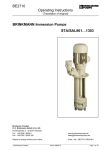
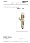
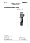
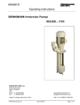
BE2710
Operating Instructions
(Translation of original)
BRINKMANN Immersion Pumps
STA/SAL901…1303
Brinkmann Pumpen
K. H. Brinkmann GmbH & Co. KG
Friedrichstraße 2 D-58791 Werdohl
Tel.: +49-2392 / 5006-0
Fax.: +49-2392 / 5006-180
www.BrinkmannPumps.com
[email protected]
Subject to change without prior notice.
Order - No. : BE2710 ENGLISH
© Brinkmann Pumpen
Edition 04/2010
Page 1 of 10
Brinkmann Immersions pumps of the series STA/SAL901 ... 1303
Contents
1 2 3 4 5 6 7 8 Indication to the manual .................................... 2 Description of product .................................... 2-4 Safety instructions .......................................... 4-5 Transport and storage ....................................... 5 Installation and connection ............................. 5-6 Start up / Shut down .......................................... 6 Operation........................................................... 6 Servicing and Maintenance ............................... 7 1 Indication to the manual
This operating manual gives basic instructions
which are to be observed during installation, operation and maintenance of the pump. It is therefore
imperative that this manual be read by the responsible personnel and operator prior to assembly and
commissioning. It is always to be kept available at
the installation site.
9 10 11 12 13 Trouble shooter’s guide ..................................... 7 Spare part ...................................................... 8-9 Repair ............................................................... 9 Disposal ............................................................ 9 EC declaration of conformity ........................... 10 2.2 Intended use
The immersion pumps of the series STA/SAL are
suitable for handling contaminated coolants within
the limiting application in accordance with table 1.
The pumps of SAL are suitable for handling extremely inflated fluids.
Limit of Application (Table 1)
1.1
Type
STA901...1303
Mediums
or where electrical safety is involved, with:
Kinetic viscosity
of the medium
Temperature of
medium
Particle-size in
the medium
Water, cooling emulsions, cooling- and cutting-oils
...90 mm2/s
...90 mm2/s
Identification of safety instructions in the
operating manual
Safety instructions given in this manual noncompliance with which would affect safety are
identified by the following symbol
Safety sign according with ISO 3864 – B.3.1
Safety sign according with ISO 3864 – B.3.6
Where non-compliance with the safety instructions
may cause a risk to the machine and it’s function
the word
min. delivery
volum
Dry running
ATTENTION
is inserted.
2 Description of product
2.1 General description of the pump
Pumps of this type are one or multi-stage rotary
pumps where the impellers are fixed on the driving
shaft extension. The pump shaft and motor shaft
are interconnected by means of a shaft clamp.
Pump and motor form a compact and space-saving
unit. These pumps are fitted out with semi-open
impellers, (and a suction screw SAL construction).
Vertically mounted pumps are equipped with a
mounting flange. The pump end immerses into the
tank and the motor extends vertically above the
tank.
BE2710
Switching-on
frequency per
hour
Ambient temperature
Set-up altitude
0 ... 80 °C
SAL901...1303
0 ... 80 °C
9 mm STA/SAL 901… 904
12 mm STA/SAL1001…1004
14 mm STA/SAL1301…1303
1% of Q max.
Dry running causes increased
wear and should be avoided.
During the test of the direction of
rotation (< 30 s) permissible.
Motors less 3 kW
max. 200
from 3 kW to 5.5 kW max. 40
from 7.5 kW to 10 kW max. 20
40 °C
1000 m
ATTENTION
The pumps are to be operated within their design
limits. Applications outside of these limits are not
approved. The manufacturer is not responsible for
any damages resulting from use of the pumps in
such applications.
Edition 04/2010
Page 2 of 10
2.3
Technical data
Max. del.
Max. del.
pressure bar / volume
spec. weight 1 l/min
Height
Weight
Depth of
STA2)
immersion
1)
STA h mm g kg
Power
kW
Noise
level3) STA
dBA / 50 Hz
STA901
/ 200 SAL901
/ 300
/ 430
/ 550
/ 750
/ 980
/1100
/ 220
/ 320
/ 450
/ 570
/ 770
/1000
/1120
2.2
930
429
200
300
430
550
750
980
1100
49
51
53
56
61
68
72
2.6
66
STA902
/ 270 SAL902
/ 370
/ 500
/ 620
/ 820
/1050
/1170
/ 290
/ 390
/ 520
/ 640
/ 840
/1070
/1190
4.3
980
504
270
370
500
620
820
1050
1170
82
85
89
93
98
105
113
5.5
71
STA903
/ 340 SAL903
/ 440
/ 570
/ 690
/ 890
/1120
/ 360
/ 460
/ 590
/ 710
/ 910
/1140
6.4
1050
542
340
440
570
690
890
1120
102
105
109
113
118
125
7.5
74
STA904
/ 410 SAL904
/ 510
/ 640
/ 760
/ 960
/1190
/ 430
/ 530
/ 660
/ 780
/ 980
/1210
8.6
1100
592
410
510
640
760
960
1190
121
124
128
132
137
142
10
74
STA1001 / 210 SAL1001 / 230
/ 310
/ 330
/ 440
/ 460
/ 560
/ 580
/ 760
/ 780
/ 990
/1010
/1110
/1130
2.2
1200
429
210
310
440
560
760
990
1110
50
52
54
57
62
69
73
2.6
63
STA1002 / 290 SAL1002 / 310
/ 390
/ 410
/ 520
/ 540
/ 640
/ 660
/ 840
/ 860
/1070
/1090
/1190
/1210
4.3
1300
504
290
390
520
640
840
1070
1190
83
86
90
94
99
106
111
5.5
71
STA1003 / 370 SAL1003 / 390
/ 470
/ 490
/ 600
/ 620
/ 720
/ 740
/ 920
/ 940
/1150
/1170
6.0
1350
542
370
470
600
720
920
1150
103
106
110
114
119
126
7.5
74
STA1004 / 450 SAL1004 / 470
/ 550
/ 570
/ 680
/ 700
/ 800
/ 820
/1000
/1020
/1230
/1250
8.4
1400
592
450
550
680
800
1000
1230
127
130
134
138
143
150
10
74
STA1301 / 210 SAL1301 / 230
/ 310
/ 330
/ 440
/ 460
/ 560
/ 580
/ 760
/ 780
/1010
/ 990
/1130
/1110
2.5
1400
468
210
310
440
560
760
990
1110
57
59
61
64
69
76
79
4.0
71
Type
BE2710
Type
H mm
Edition 04/2010
Page 3 of 10
Max. del.
Max.
pressure bar / del. volume
spec. weight 1 l/min
Height Depth of
Weight Power
2)
STA
immersion
1)
H mm STA h mm g kg
kW
Noise
level3) STA
dBA / 50 Hz
STA1302 / 290 SAL1302 / 310
/ 390
/ 410
/ 520
/ 540
/ 640
/ 660
/ 840
/ 860
/1070
/1090
4.7
1600
542
290
390
520
640
840
1070
95
98
102
106
111
118
7.5
74
STA1303 / 370 SAL1303 / 390
/ 470
/ 490
/ 600
/ 620
/ 720
/ 740
/ 920
/ 940
/1150
/1170
6.9
1680
592
370
470
600
720
920
1150
115
118
124
126
131
138
10
74
Type
Type
1) Depth of immersion SAL = h + 20 mm ; 2) Weight SAL = g + 1 kg
3) Noise emissions measured in accordance with DIN 45635 at a distance of 1 m The motor is surface-cooled and compliant with
DIN IEC 34 and EN 60034 (protection degree IP 55).
3.3
3 Safety instructions
When operating the pump, the safety instructions
contained in this manual, the relevant national
accident prevention regulations and any other
service and safety instructions issued by the plant
operator are to be observed.
3.1
Hazards in the event of non-compliance
with the safety instructions
Non-compliance with the safety instructions may produce
a risk to the personnel as well as to the environment and
the machine and results in a loss of any right to claim
damages.
For example, non-compliance may involve the following
hazards:
• Failure of important functions of the machines/plant
• Failure of specified procedures of maintenance
and repair
• Exposure of people to electrical, mechanical and
chemical hazards
• Endangering the environment owing to hazardous substances being released
3.2
Unauthorized modes of operation
Risk of Injury!
Risk of squeezing or crushing body parts when
installing or removing the pump exists. Proper and
secured lifting tools must be used.
Risk of burns!
The pump must have cooled down sufficiently prior
to commencing any repair, maintenance or installation.
3.4
Qualification and training of operating
personnel
The personnel responsible for operation, maintenance, inspection and assembly must be adequately
qualified. Scope of responsibility and supervision of
the personnel must be exactly defined by the plant
operator. If the staff does not have the necessary
knowledge, they must be trained and instructed,
which may be performed by the machine manufacturer or supplier on behalf of the plant operator.
Moreover, the plant operator is to make sure that
the contents of the operating manual are fully
understood by the personnel.
3.5
• Pump may not be used in potentially explosive
environments!
• Pump and discharge piping are not designed to
hold any weight and may not be used as a stepping ladder.
Remaining Risk
Safety instructions relevant for operation
• If hot or cold machine components involve
hazards, they must be guarded against accidental contact.
• Guards for moving parts (e.g. coupling) must not
be removed from the machine while in operation.
• Any leakage of hazardous (e.g. explosive, toxic,
hot) fluids (e.g. from the shaft seal) must be
drained away so as to prevent any risk to persons or the environment. Statutory regulations
are to be complied with.
BE2710
Edition 04/2010
Page 4 of 10
• Hazards resulting from electricity are to be
prevented (see for example, the VDE Specifications and the bye-laws of the local power supply
utilities).
of the pumps cross section for connection. Therefore pipe bends should be used, not pipe angles!
The pipework must be qualified for occuring hydraulic pressure.
• The pumps’ stability against falling over is not
ensured unless it is properly mounted onto the
tank.
ATTENTION
• The famale threads on the motor MUST NOT be
used to lift the entire pump and motor assembly.
3.6
Safety instructions relevant for maintenance, inspection and assembly work
Any work on the machine shall only be performed
when it is at a standstill, it being imperative that the
procedure for shutting down the machine described
in this manual be followed.
Pumps and pump units which convey hazardous
media must be decontaminated.
On completion of work all safety and protective
facilities must be re-installed and made operative
again.
Prior to restarting the machine, the instructions
listed under “Start up” are to be observed.
3.7 Signs on the pump
It is imperative that signs affixed to the machine,
e.g.:
• arrow indicating the direction of rotation
• symbols indicating fluid connections
be observed and kept legible.
3.8
Unauthorized alterations and production
of spare parts
Any modification may be made to the machine only
after consultation with the manufacturer. Using
spare parts and accessories authorized by the
manufacturer is in the interest of safety. Use of
other parts may exempt the manufacturer from any
liability.
4 Transport and storage
Protect the pump against damage when transporting.
The pumps may only be transported in a horizontal
position and hooks or straps must be attached on
the motor and pump end.
Do not use the pump shaft for connecting any
transportation aids such as hooks or straps.
Pumps must be drained prior to their storage.
Store pump in dry and protected areas and protect
it against penetration of foreign bodies.
Maximum tightening torque for piping connections is 150 Nm!
When installed the space around the pump
must be large enough to provide sufficient
cooling of the motor.
The pump must be mounted in that way that
rotating parts under the cover of the coolant
tank can not be touched!
5 Installation and Connection
5.1 Mechanical installation
During any assembly or disassembly process the
pumps must be secured against tipping trough
ropes for example at all times.
Pumps must be mounted securely. Piping, tank and
pumps must be mounted without any tension.
The inlet is at the bottom of the immersed pump
body. The distance between the inlet and the tank
bottom must be so large that the inlet can not be
blocked by deposits during longer shutdowns.
To obtain the full flow rate it is recommended to
choose for the pipework the nominal bore diameter
BE2710
Edition 04/2010
Page 5 of 10
5.2
6 Start up / Shut down
Electric wiring
6.1
Start up
ATTENTION
All service work must be carried out by qualified service personnel. Pump must be disconnected from the power source and all rotating
parts must stand still. Reassure that pump is
disconnected from power source and cannot be
switched on. Verify that there is no voltage at
the terminal board!
According to the European Standard EN809 a
motor overload must be installed and properly set
to the full load amps stated on the pump name
plate.
It is the responsibility of the machine operator to
decide whether or not an additional emergency
switch must be installed.
5.2.1
Circuit
Switch off at the mains.
After connection of the terminals close the terminal
box. Briefly start the motor (max. 30 sec.) and
check the rotation according to the arrow on the top
of the motor.
If the direction is incorrect change over two of the
power leads.
6.2 Shut down
All service work must be carried out by qualified
service personnel. Pump must be disconnected
from the power source and all rotating parts must
stand still. Reassure that pump is disconnected
from power source and cannot be switched on.
Verify that there is no voltage at the terminal board!
Open terminal box and disconnect the power leads.
Empty out the pump.
7 Operation
Tension voltage and frequency must correspond
with the shown specification on the nameplate.
The pump must be wired so that a solid longterm
electrical connection is ensured. Establish a solid
ground connection.
The electrical wiring must be performed according to the wiring diagram shown inside the
terminal box cover. (Please see above sample
wiring diagrams)
Liquid level
According to the drawing shown below, the
maximum liquid level must stay about 30 mm below
the mounting flange, also ensure that the minimal
liquid level for the STA pump is 60 mm before
starting up the motor, for the SAL pump the suction
hole of the pump body must be covered with liquid.
Wiring diagram e.g.
Star connection
3 x 400 V, 50 Hz
resp. 380-420 V, 50 Hz
Delta connection
3 x 230 V, 50 Hz
resp. 220-240 V, 50 Hz
There may be no foreign objects such as dirt,
particles or humidity inside the terminal board.
Mount terminal board cover to motor tight against
dust and humidity and close up all unused wiring
ports.
ATTENTION
When Variable Frequency Drives are used interfering signals might occur.
Non-sinus shaped supply voltage from a variable
frequency drive might result in elevated motor
temperatures.
BE2710
If the pump should lock up and cease, shut
pump down (see 6.2) and disconnect from
power supply. Pump must be uninstalled and
removed from the system prior to its repair.
Edition 04/2010
Page 6 of 10
8 Servicing and Maintenance
ATTENTION
The surface of the motor must be kept free of dirt.
The motor shaft is spinning in permanently greased
ball bearings (with special grease and increased
bearing play) and does not require any special
maintenance.
9 Trouble shooter’s guide
Fault
Cause
Remedy
Motor does not start, no motor
noise
At least two of the power supply
leads have failed
Check fuses, terminals and supply
leads .
Overload has tripped
Inspect overload
One of the supply leads has failed
See above
Impeller faulty
Motor bearing faulty
Replace impeller
Replace bearing
Overload trips
Pump locked up mechanically
High on/of cycling frequency
Inspect pump hydraulics
Check application
Power consumption is too high
Wrong direction of rotation of
impeller
Lime or other deposits
mechanical friction
See above
High on/off cycling frequency
Wrong power supply (voltage or
cycles)
See above
Power supply must correspond with
name plate rating
Insufficient cooling
Check air flow at motor fan
Pump does not pump
liquid level too low
Pump mechanism faulty
Pipe blocked
Fill up liquid
replace pump mechanism
Clean pipe
Insufficient flow and pressure
Wrong direction of rotation of
impeller
Change over two power supply
leads
Pump mechanism silted up
Worn pump mechanism
Clean pump mechanism
Replace pump mechanism
Incorrect flow or pressure
Wrong power supply (voltage or
cycles)
Power supply must correspond with
name plate rating
Running noise/Vibration
Foreign objects in pump end
Impeller damaged
Bearing/Bushing broken
Remove foreign objects
Replace impeller
Replace bearing/bushing
Motor does not start, humming noise
Motor overheats
BE2710
Edition 04/2010
Clean pump mechanism
repair pump
Page 7 of 10
10 Spare part
10.1 Spare part list for the immersion pumps
of the series STA/SAL901 ... 1303
Item Description
1 Stator with terminal board
2 Motor flange
3 End shield
4 Terminal box up to 5.5 kW
5 Terminal box frame up 7.5 kW
6 Terminal box cover up 7.5 kW
7 Fan
8 Fan cover
9 Ball bearing up to 5.5 kW
DIN 625
9 Ball bearing up 7.5 kW
DIN 628
10 Ball bearing
DIN 625
11 Gasket
12 Gasket up 7.5 kW
13 Retaining ring
14 Thread rolling screw
DIN 7500
15 Slotted cheese head screw
DIN 84
16 Socket head cap screw
DIN 912
17 Socket head cap screw
DIN 912
19 Parallel pin
DIN 7
20 Shaft seal
21 Retaining ring
DIN 472
DIN 471
22 Retaining ring
23 Compensation disk
25 O-ring
50 Pump body
51 Shaft with rotor
52 Inlet cover for STA
52 Intake cover for SAL
53 Pump plate up STA/SAL902, 1002, 1302
55 Impeller
57 Suction screw only for SAL
58 Extension pump body up 750 mm depth of
immersion
59 Distance liner
60 Distance liner
61 Running sleeve
62 Bearing bush
63 Distance plate
64 Woodruff key
DIN 6888
66 O-ring up 750 mm depth of immersion
67 O-ring
68 Splash ring
69 Splash ring
72 Socket head cap screw
DIN 912
74 Stud bolt STA/SAL1302...1303
75 Hexagon domed cap nut
DIN 1587
STA/SAL1302...1303
77 Hexagon thin nut STA
78 Socket head cap screw
DIN 912
up 750 mm depth of immersion
82 Joining socket
83 Socket head cap screw
DIN 912
84 Spring washer
DIN 7980
85 O-ring
86 Screw plug
DIN 908
87 Sealing ring
DIN 7603
88 Serrated lock washer
89 Flat head screw
DIN 7991
91 Extension shaft up 750 mm depth of im.
92 Insert shaft
93 Shaft clamp 2 x up 750 mm depth of im.
BE2710
Edition 04/2010
Page 8 of 10
10.2 Indications to the spare part order
Spare parts are available from the supplier.
Standard commercially available parts are to be
purchased in accordance with the model type.
The ordering of spare parts should contain the
following details:
1. Pumptype
e.g. STA902 / 370
2. Pump No.
e.g. 11072710
The date of the construction year is a component of the pumps type number.
3. Voltage, Frequency and Power
Take item 1, 2 and 3 from the nameplate
4. Spare part with item No.
e.g. Intake cover item No. 52
11 Repair Instructions / Replacing shaft
clamps and shafts
3
1
2
11.2 Assembling the insert shaft and motor
shaft
ATTENTION
Clean the contact surfaces of the insert shaft (2)
(inside) and the motor shaft (3). They must not
be lubricated or oiled.
– Set the motor down on the fan cover.
– Position the shaft clamp (1) (use a new shaft
clamp) in the centre of the cranked clamping diameter (2) of the insert shaft.
– Insert the motor shaft (3) into the insert shaft (2).
– Tighten:
Mark the first screw and tighten all the screws
evenly by hand, one after the other in a clockwise direction (not cross-ways).
– Use a torque screwdriver to tighten each screw
first with 2 Nm then with 3.5 Nm and finally with
5 Nm (in a clockwise direction again).
– Mount the pump body.
The remainder of the reassembly process is to be
completed in the opposite order of the prior described dismantling process.
ATTENTION
1 = Shaft clamp
2 = Insert / extension shaft
3 = Motor shaft / Insert shaft
11.1 Dismantling the insert shaft or extension
shaft
– Disconnect the submergible pump from the
mains both electrically and mechanically.
– Remove pump from system. Secure pump
against tipping over, i.e. use ropes to secure
pump.
– Set the pump down on the fan cover. Dismantle
the pump unit and the extension pump body (if
appropriate).
Wear safety gloves!
Risk of injury due to sharp edges on pump components, i.e. impeller blades.
– Loosen the screws on the shaft clamp (1) one
after the other.
Note torques for the screw connections!
When putting the pump back into use, make sure
the direction of rotation is correct!
Tightening torques for screwed connections
Thread - ∅
Strength
classes
Tightening
torque (Nm)
M5
4.8
M8
8.8
M16
8.8
M16
3 Nm
20 Nm
(4,5 Nm
Item. 3)
60 Nm
60 Nm
Item. 83 Item. 77
12 Disposal
When disposing of the pump or the packaging
materials the local and national regulation for
proper disposal must be complied with.
Prior to its disposal, the pump must be completely
drained and decontaminated if necessary.
Do not, under any circumstances, remove the screws
completely, danger of injury!
– Remove the extension shaft (2) and shaft clamp
(1).
– Dismantle the pump body.
– Loosen the screws on the shaft clamp (1) (see
above), pull the insert shaft (2) off the motor
shaft (3).
BE2710
Edition 04/2010
Page 9 of 10
13 EC declaration of conformity
DEUTSCH / ENGLISH /FRANÇAIS / ESPAÑOL
EG-Konformitätserklärung
EC declaration of conformity / Déclaration de conformité CE / Declaración de conformidad CE
Hersteller / Manufacturer / Constructeur / Fabricante
Brinkmann Pumpen, K. H. Brinkmann GmbH & Co. KG
Friedrichstraße 2, D-58791 Werdohl
Produktbezeichnung / Product name / Désignation du produit / Designación del producto
Tauchpumpen / Immersion pumps / Pompes plongeantes / Bombas de inmersión
Typ / Type / Tipo
STA/SAL901…1303
Das bezeichnete Produkt stimmt mit den folgenden Richtlinien des Rates zur Angleichung der Rechtsvorschriften der
EG-Mitgliedsstaaten überein:
The named product conforms to the following Council Directives on approximation of laws of the EEC Member States:
Le produit sus-mentionné est conforme aux Directives du Conseil concernant le rapprochement des législations des
Etats membres CEE:
El producto designado cumple con las Directivas del Consejo relativas a la aproximación de las legislaciones de los
Estados Miembros de la CEE:
2006/42/EG
2006/42/EC
2006/42/CEE
2006/42/CEE
Richtlinie für Maschinen
Council Directive for machinery
Directive du Conseil pour les machines
Directivas del Consejo para máquinas
2004/108/EG
2004/108/EC
2004/108/CEE
2004/108/CEE
Richtlinie für elektromagnetische Verträglichkeit
Council Directive for Electromagnetic compatibility
Directive du Conseil pour Compatibilité électromagnétique
Directivas del Consejo para Compatibilidad electromagnética
Hinsichtlich der elektrischen Gefahren wurden gemäß Anhang I Nr. 1.5.1 der Maschinenrichtlinie 2006/42/EG die Schutzziele der Niederspannungsrichtlinie 2006/95/EG eingehalten.
With respect to potential electrical hazards as stated in appendix І No. 1.5.1 of the machine guide lines 2006/42/EG all
safety protection goals are met according to the low voltage guide lines 2006/95/EG.
Conformément à l'annexe I N° 1.5.1 de la Directive "Machines" (2006/42/CE) les objectifs de sécurité relatifs au
matériel électrique de la Directive "Basse Tension" ont été respectés.
Con respecto al potencial peligro eléctrico como se indica en el apéndice I No. 1.5.1 del manual de la máquina
2006/42/EG, todos los medios de protección de seguridad se encuentran según la guía de bajo voltaje 2006/95/EG.
Die Übereinstimmung mit den Vorschriften dieser Richtlinien wird nachgewiesen durch die vollständige Einhaltung folgender Normen:
Conformity with the requirements of this Directives is testified by complete adherence to the following standards:
La conformité aux prescriptions de ces Directives est démontrée par la conformité intégrale avec les normes suivantes:
La conformidad con las prescripciones de estas directivas queda justificada por haber cumplido totalmente las siguientes
normas:
Harmonisierte Europ. Normen / Harmonised Europ. Standards / Normes europ. harmonisées / Normas europ. armonizadas
EN ISO 12100-1 EN ISO 12100-2 EN 60204-1 EN 61000-3-2 EN 61000-3-3 EN 61000-6-2 EN 61000-6-3
Nationale Normen / National Standards / Normes nationales / Normas nacionales: EN 60034-1
Die Hinweise in der Betriebsanleitung für den Einbau und die Inbetriebnahme der Pumpe sind zu beachten.
The instructions contained in the operating manual for installation and start up the pump have to be followed.
Les indications d’installation / montage et de mise en service de la pompe prévues dans l’instruction d’emploi
doivent être suivies.
Tenga en cuenta las instrucciones en el manual para la instalación y puesta en marcha de la bomba.
Brinkmann Pumpen, K. H. Brinkmann GmbH & Co. KG
Werdohl, 24.04.2010
...............................................................................................
Leiter Qualitätssicherung / Manager of quality assurance
Directeur d’assurance de la qualité / Director del aseguramiento de calidad
BE2710
Edition 04/2010
Page 10 of 10