1
TeleVideo@ .
TS 806/20 Computer System . .
Installation and User's Guide
d~
"
.---:_
.....
~,TeleVideo Systems, Inc.
TeleVideo@
TS 806/20 Computer System
Installation and User's Guide
TeleVideo Document No. 2226500
October 1982
Copyright (c) 1982 by TeleVideo Systems, Inc. All rights reserved. No part of this publication may be reproduced,
transmitted, transcribed, stored in a retrieval system, or translated into any language or computer language. in
any form or by any means, electronic, mechanical, magnetic, optical, chemical, manual, or otherwise, without the
prior written permission of TeleVideo Systems, Inc., 1170 Morse Avenue, Sunnyvale, California 94086.
Disclaimer
TeleVideo Systerl1s, Inc. makes no representations or warranties with respect to this manual. Further, TeleVideo
Systems, Inc. reserves the right to make changes in the specifications of the product described within this manual
at any time without notice and without obligation of TeleVideo Systems, Inc. to notify any person of such revision
or changes.
"Warning: This equipment generates, uses, and can radiate radio frequency energy, and if not installed and used
in accordance with the instruction manual may cause interference to radio communications. As temporarily permitted by regulation, it has not been tested for compliance with the limits for Class A computing devices pursuant
to Subpart J of Part 15 of FCC Rules, which are designed to provide reasonable protection against such interference. Operation of this equipment in a residential area is likely to cause interference, in which case the user at his
expense will be required to correct the interference."
TeleVideo® is a registered trademark of TeleVideo Systems, Inc.
Z80A® is a registered trademark of ZILOG Corporation.
CP/M® is a registered trademark of Digital Research, Inc.
RM/COBOL ™ is a tradefXIar~ .of Ryan-McFarland Corp.
MmmOST™ is a trademark of TeleVideo Systems, Inc.
TeleVideo COBOL TM is a trademark of TeleVideo Systems, Inc.
WordStar™ is a trademark of MicroPro International Corporation.
TeleVideo Systems, Inc. 1170 Morse Avenue Sunnyvale, California 94086 408/745-7760
TABLE OF CONTENTS
Page
LIST OF FIGURES ................................................................. v
LIST OF TABLES .................................................................. vi
1.
INTRODUCTION ............................................................. 1-1
1 .1
1.2
1.3
1.4
1.5
2.
Introduction ............................................................
Turning On the User Station .. : .................... ' ........................
Types of Drives in the Multiuser Environment ..................................
Booting the User Station . . . . . . . . . . . . . . . . . . . . . . . . . . . . . . . . . . . . . . . . . . . . . . . . ..
Operating Under MmmOST ...............................................
Working with MmmOST ..................................................
4-1
4-1
4-1
4-3
4-3
4-6
OPERATIONAL GUIDELINES. . . . . . . . . . . . . . . . . . . . . . . . . . . . . . . . . . . . . . . . . . . . . . . . . .. 5-1
5.1
5.2
5.3
5.4
'5.5
5.6
6.
Introduction ............................................................ 3-1
Initial Start Up ........................................... '. . . . . . . . . . . . . .. 3-1
OPERATING THE USER STATIONS ............................................. 4-1
4.1
4.2
4.3
4.4
4.5
4.6
5.
Unpacking .................................................. '. . . . . . . . . . .. 2-1
Software Registration .................................................... 2-3
Selecting the Right Location ............................................ '... 2-3
Installation ............................... ~ ............................. 2-4
Checklist of Installation Instructions ......................................... 2-10
OPERATING THE SERVICE PROCESSOR ........................................ 3-1
3.1
3.2
4.
1-1
1-1
1-3
1-5
1-6
SYSTEM INSTALLATION ...................................................... 2-1
2.1
2.2
2.3
2.4
2.5
3.
System Description . . . . . . . . . . . . . . . . . . . . . . . . . . . . . . . . . . . . . . . . . . . . . . . . . . . . ..
Limited Warranty. . . . . . . . . . . . . . . . . . . . . . . . . . . . . . . . . . . . . . . . . . . . . . . . . . . . . . ..
Hardware Configuration ..................................................
Software Overview ............ . . . . . . . . . . . . . . . . . . . . . . . . . . . . . . . . . . . . . . . . ..
Using the Manual .......................................................
Introduction ............................................................
Flopp'y Diskettes ...................................................
Write-Protecting Diskettes .................................... .' ...........
Backing Up the Hard Disk ............... ~ . . . . . . . . . . . . . . . . . . . . . . . . . . . . . . . . .
Work Habits ............................................................
Summary of Good Practices ...............................................
I
•
•
••
5-1
5-1
5-6
5-7
5-7
5-8
UTILITY' PROGRAMS ..........................•............ , . , .... , . . . . . . . . .. 6-1
6.1
6.2
Introduction ............................................................ 6-1
Using the Utility Programs . . . . . .. . . . . . . . . . . . . . . . . . . . . . . . . . . . . . . . . . . . . . . . . .. 6-1
iii
TABLE OF CONTENTS
Page
7. . r SYSTEM TROUBLESHOOTING AND GENERAL MAINTENANCE ...................... 7-1
7.1
7.2
7.3
7.4·
Care ..................................................................
Troubleshooting ... '............... ~ ~ ...........' . . . . . . . . . . . . . . . . . . . . . . . . . .
Changing the Exterior Fuse ...............................................
How to Get Service . ~ ~ ... ; ........ : ... : . : . . . . . . . . . . . . . . . . . . . . . . . . . . . . . . . . .
7-1
7-1
7-3
7-4
AP'~ENDICES
·:···.··A.
O,<S ..
~·C.
:·0.
E.
F.
G.
H.
TS 806/20 Specif,ications ....... ;.........................................
Statement· of Limited Warranty ... ; : ; ; . . . . . . . . . . . . . . . . . . . . . . . . . . . . . . . . . . . . . .
Suggested References ... : .. ; ~ .. ~ ..... ~ . . . . . . . . . . . . . . . . . . . . . . . . . . . . . . . . . .
Pin Connector Assignments ....... ~ .... ~ . . . . . . . . . . . . . . . . . . . . . . . . . . . . . . . . . .
Port Asssignments ......................................................
Buying Additional Diskettes ...............................................
Cable Specifications ........................................... . . . . . . . . . . .
Using the Time and Date Capability in Applications Programs .....................
A-1
B-1
C-1
0-1
E-1
F-1
G-1
H-1
INDEX . . . . . ..... . . . . . . . ., ........, ............. ',' .......................... '......... X-1
iv
LIST OF FIGURES
.,'
!~.'
~
,.'
"....
t· •..
"".~ .~.
or
Page
1-1 . TS 806/20 Computer System ................. '........ ',' ............. : ..........
1-2 Possible TS 806/20 Configurations .............................................
.
'\ -;
",
1-3 Floppy Diskette ....................;............................... ..;. ::.' . ..
1-4 Diskette Inside Permanent Plastic Enclosure ................ ; .......... .' .....' ... .".
I
.,
"
r.(.~r
~.~ . "
••••
:
1-1
1-2
3
11-4
t"
2-1
2-2
2-3
2-4
2-5
2-6
Cable Connector ............................................................... '\; 2-5
Correctly-Folded Excess Ribbon Cable ......................................: .... 2-6
Rear Panel of the TS 806/20 .................................................. 2-6
Location of Screws in the TS 806/20 Case .. ~ : ...... ~ . ~ ..... ':~'~,~.' ..: ~ ',.' :\~:.:.. ' .:::.~ .... 2-7
Location of Internal Switch 1 ...... ~ ....... ~ ~ ~ ~ ........... ~ ...... ,.:................ ' :,2-7
Closed and Open Switches ........... : .... :.:. ~ .. ~ ....... ~ .. ~ . , 'J • ';' ~./; • • • • • • • )2-8
3-1
3-2
3-3
On/Off Switch on Rear Panel ............... ; ....................... ~ ... ::~.: ........ 3-1
Location of Reset Button ...........................................:". . . . . . . . .. 3-2
Service Processor Terminal System Message ........................ ;":.~ ..... <. . . .. 3-6
5-1
5-2
5-3
5-4
5-5
5-6
5-7
5-'8'
5-9
Opening Floppy Drive Door ......... ,..~ .............. ':' . ... . . . . . . . . . . . . . . . . . . . . ..
Removing Diskette From Jacket .... ". '. . . . . . . . . . . . . . . . . . . . . . . . . . . . . . . . . . . . . . . . ..
Write-Protecting Diskette ...................................... : . . . . . . . .. . . . . . ..
Holding Diskette Before Insertion ...............................................
Inserting Diskette in Floppy Drive ...............................................
Diskette Tracks and Sectors ..................................................
Diskette and Protective Lining Inside the Protective Black Plastic' Enclosure ..............
Write-Protected Diskette .....................................................
Typical Back-Up System ........................... '. . . . . . . . . . . . . . . . . . . . . . . . . ..
5-1
5-2
5-2.
5-3
5-3
5-4
5-5
5-6
5-7
7 -1
7-2
7-3
7-4
Location of Exterior Fuse . . . . . . . . . . . . . . . . . . . . . . . . . . . . . . . . . . . . . . . . . . . . . . . . . . . ..
Good Fuse . . . . . . . . . . . . . . . . . . . . . . . . . . . . . . . . . . . . . . . . . . . . . . . . . . . . . . . . . . . . . . ..
Burned Out Fuse ...........................................................
Location of Serial Number on Rear Panel . . . . . . . . . . . . . . . . . . . . . . . . . . . . . . . . . . . . . . . ..
7-3
7-3
7-3
7-4
G-1
G-2
RS232C..................................... . . . . . . . . . . . . . . . . . . . . . . . . . . . . . G-1
RS422 ...................................... : ................... ~ . . . . . . . . . G-1
~
v
":
..
LIST OF TABLES
Page
,
1
'.
1~ 1 " TS ,806/20 Ports .....................................' ... '.. '. . . . . . . . . . . . . . . . .. 1-5
2~1
Cable Specifications . . . . . . . . . . . . . . . . . . . . . . . . . . . . . . . . . . . . . . . . . . . . . . . . . . . . . . . .. 2-5
2~2 . $witch Settings for RS232 Terminal Port Switch 1 ................................. 2-8
2-3 , Setting Baud Rate of Termi~al Port on Switch f ................................... 2-9
':,
.3-1
'
'
Hardware Error Abbreviations ................................................. 3-6
4-1 :T5 ,~061?O Logical and Physical Drives .......................................... 4-2
4-2· Logical Drive Capacities ... ' ... '... '............". . . . . . . . . . . . . . . . . . . . . . . . . . . . . . . . . .. 4-2
. 6·' , Utility Prograrns Run From a Service Processor Terminal ............................
:6-2 ',Utility Program Format. . . . . . . . . . . . . . . . . . . . . . . . . . . . . . . . . . . . . . . . . . . . . . . . . . . . . ..
,6-3 Utility Programs ................... ,...... .' ...................................
6-4 COPYFILE Error Messages ....................................................
6-1
6-2
6-2
6-6
7-1
r:roubleshooting Procedures .................................................. 7-1
0-1
0-2
0-3
P2 Connector Assignments ................................................... D-1
P7 Connector Assignments ................................................... 0-1
P4 Connector Assignments ................................................... D-2
vi
1.
INTRODUCTION
1. 1
SYSTEM DESCRIPTION
...'
.....
...,.,.....,.........
,
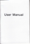
The TeleVideo TS 806/20 is a compact tabletop multiuser microcomputer which can:support up
to six user stations. A Winchester h~rd disk and floppy diskettes provide centr~l,storage 9f data.,
for all users. Figure 1-1 shows the TS 806/20 unit.
! . .'
'I' ", ,,)'.
"
t
I,; ,~ ,
:
,:'
:,', '
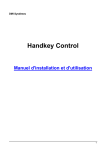
Many combinations of peripheral devices can be attached to the TS 806/20-seri~1 and parallel '
printers, a service processor terminal, or modem. Figure 1-2 illustrates several of the possible '
configurations.
.,
.( ,
. "':,.
! ..,·r
AIR VENTS
~
\
.~.
,
4>-------~--.---
,
..
,.\
- - - - -... - .. - - - . - - - . - - - - - . - -... - ....-...- - - - - - - - - - - . . . . . . . . . j
FLOPPY DRIVE
RESET BUnON
Figure 1-1
1.2
TS 806/20 Computer System
LIMITED WARRANTY
The TS 806/20 is covered by a limited warranty. The terms and conditions of the complete limited warranty are provided in Appendix ~.
Read the installation instructions completely before turning on your system. Incorrect installa-
tion may void the warranty.
1-1
1.
INTRODUCTION
PRINTER
PRINTER
TS 806/20 SERVICE PROCESSOR
TS802
TS800A
Figure 1-2 Possible TS (J06/20 Configurations
1-2
TS802H
1.
INTRODUCTION
1.3
HARDWARE CONFIGURATION
1.3.1
Hardware Overview
================================================================"
The TS 806/20 is a tabletop computer which contains 'the following components:
One 5 1/4-inch Winchester hard disk drive
One 51/4-inch floppy disk drive
Specification details are given in Appendix A.
The TS 806/20 will be referred to as the service processor.
1.3.2
Disk Drives
The TS 806/20 has one 5 1/4-inch Winchester hard disk drive and one 5 1/4-inch floppy disk
drive.
,
The floppy disk drive is located on the left side of the computer. (See Figure 1-1 .)
The Winchester disk drive is located immediately to the right of the floppy disk, drive.
1.3.3
Hard Disk and Floppy Diskettes
The hard disk is permanently sealed in an air-tight enclosure and is not accessible to you. It has a
capacity of 19.14 megabytes of unformatted disk storag,e (formatted 15.04 megabytes). Data
can be stored on this hard disk and accessed by all user stations connected to the TS 806/20.
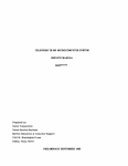
The floppy diskettes are 5 1/4-inch, double-sided, double density with a capacity of 500 kilobytes of unformatted storage (formatted 368.6 kilobytes). Figure 1-3 shows the floppy diskette.
DI
1
o·
I
Figure 1-3 Floppy Diskette
Each diskette has a magnetic coating on both sides, much like a phonograph record. Unlike a
phonograph record, it arrives in a protective black plastic cover which is NOT removable. Lubricants inside this cover increase the life of the diskette. The actual diskette can be seen through
some of the slots in the plastic cover.
1-3
I
1.
INTRODUCTION
Figure 1-4 shows the actual floppy diskette and protective lining inside the plastic cover. When
cared for properly (as described in Chapter 5), diskettes can be used many times .
.... 1.- _
..,..1"\
""''',../nn ___ . ____ .... _ _ _ ....
... Lo..:_L.. '_ _ _ ,,_ ........ _ _ ...... _ _ :,:,,_+: ............ ,... ,..; •• " .... i .....
veil I U\)t: C1lly lIutJtJy UI.,,,t:Ut; ¥Vlllvil 11It;t;"" "llv ;::)t<JvvlllvClUV"~ ~'Yv" '"
~
~I
"':_II'_"'~_
I lit: I \:) OUOI t:.u
!\
"'~l""\n,...,i'V
~I-'I-''"''''-''''
r::
I
•
New diskettes must be formatted before data can be stored on them (as explained in 5.2.2).
Figure 1-4
Diskette Inside Permanent Plastic Enclosure
Applications programs, text, data, and programs which operate the TS 806/20 can be stored on
either the hard disk or floppy diskettes.
1.3.4
Peripheral Devices
The ports on the rear of the TS 806/20 allow you to connect a wide variety of peripheral devices.
Up to six user stations can be attached to the TS 806/20. These user stations may (but do not
need to) have their own data storage. In addition to the user stations, a service processor terminal is used to run utility programs, run service diagnostics, modify the operating parameters of
MmmOST, and monitor the operation of the TS 806/20. A user station can also operate as a
service processor terminal by changing the switch setting on the rear panel. Refer to the operator's manual for location and settings of the switch. '
Optional peripheral devices can be shared by all user stations. For hardcopy output, you can
connect a serial printer to the port labeled RS232 [OPT]. (This could be a dot matrix, line, or
letter-quality printer.) This interface is compatible with most RS232-compatible serial printers
currently available on the market, including both character-by-character and buffered printers.
A serial device, such as a modem, can be attached to the RS232 [OPT] port instead of a printer.
You can attach a parallel Centronics-type printer to the port labeled PRINTER.
Refer to Figure 1-2 where several possible configurations are illustrated.
The peripherals described here are al/ in addition to those which may be connected directly to
each user station.
1-4
1.
INTRODUCTION
Table 1-1
Port
Description
TERMINAL
This 25-pin RS232 port is used to connect a service processor terminal. This port is used
for running system utility programs, monitoring the TS 806/20 operation. running service
diagnostics, and modifying the MmmOST parameters.
PRINTER
RS232 [OPT]
USER 1
through
USER6
1.4
1.4.1
TS 806/20 Ports
This 36-pin port can be used to connect a parallel Centronics-type printer.
This 25-pin port is used to connect a serial printer or modem.
Six high-speed serial RS422 ports are available to connect the TS 806/20 to user stations
(any TeleVideo 8- or 16-bit system).
SOFTWARE OVERVIEW
Operating System
Every computer needs instructions in order to operate; these instructions are supplied by a
group of programs collectively called the operating system.
When the TS 806/20 is turned on, its operating system is loaded into memory from the hard disk
and then into the memory of each user station which is turned on. All TeleVideo computers use
CP/M (Control Program for Microcomputers) Operating System software, developed by Digital
Research.
If you are not already familiar with CP/M, TeleVideo highly recommends that you refer to the
reference books listed in Appendix C and become familiar with the basic operation of the CP/M
operating system.
When the TS 806/20 is used in a multiuser environment, it also uses a special program called
MmmOST. MmmOST is an acronym for Multiuser, multiprocessor, multitasking Operating System Techno.logy. MmmOST controls access by the user stations to the files and programs
stored in the TS 806/20.
1.4.2
Programming Languages
User stations can use any programming language which will run under CP/M. Among these are
BASIC, ALGOL, APL, "C," COBOL, CBASIC, FORTH, FORTRAN, MBASIC, PL/I, and RM/
COBOL. When these languages are used with MmmOST, modifications which are described in
the MmmOST Programmer's Manual allow them to take advantage of the features of
MmmOST. In addition, TeleVideo COBOL allows applications programs to be used with
MmmOST with little or no modification.
1-5
1.
INTRODUCTION
1.4.3
Applications Programs
Applications programs are commercially available for a wide range of tasks, from accounting to
"""'''':+i,,,... ,.".,......... ""... , .....:." ...".. .... "'.....
,.. ...........
r-.I"'II." .....i+,. I ....
~
Ii"' ........ :""' .... ,.. .........."',.. ... """'...,...,... : ..... 1"IiIo. .... , . . ,...,." ... a,...,.. ." .. "..,...,... .... ,...~..-.-: .... .;1~"'UI "'1. " I " V V I " I V I . , 1 v U I I 1"1 ..... " " 1vUI V .. ., I I "tJtJ""'''''IVII~ tJl V~I "III~ III V I I " VI " l l v tJl V~I alllllllll~
languages compatible with
CP/M~
Applications programs are normally run in the user stations, not in the service processor.
1.5
USING THE MANUAL
This manual will show you how to successfully install and use your new TS 806/20 regardless of
your past experience with computers. Every attempt has been made to present all of the information you will need in a complete and easy-to-understand format. Refer to the operator's manual supplied with your user station also.
Your comments about the manual are welcome. To facilitate this, we have provided a Reader
Comment Card. Please take a moment to complete and return the card after you have installed
your system.
1.5.1
Organization
The manual is organized in the sequence you will need the information. The chapters are as
follows:
2
Installation: How to unpack and install the TS 806/20
3
Operating the Service Processor: How to install CP/M and MmmOST and operate the
system'
Operating the User Stations: How to operate user stations in a multiuser environment
Operational Guidel~nes: How to effectively use the system.and floppy diskettes
Utility Programs: How to use the system utility programs
Maintenance and Troubleshooting: How to care for the TS 806/20 and what to do if you
have a problem
4
5
6
7
In the Appendices are the specifications, limited warranty, suggested references, and technical
information.
1.5.2
Special Information
Notes will call your attention to information which is of special importance. These categories of
notes are used:
General useful information
Important information concerning your safety or possible loss of data. When you
see this, STOP and read the note before proceeding!
1.5.3
Format of Control Commands
Control commands will be shown as 1\ plus the control character (e.g., I\C).
1.5.4
Carriage Returns
When you should press the RETURN key on the operator's keyboard, the symbol <CR> for
CARRIAGE RETURN will be used. (On Televideo terminals, you can press the ENTER key in.
stead of the RETURN key.)
1-6
2.
SYSTEM INSTALLATION
2. 1
2.1.1
UNPACKING
How to Unpack
The TS 806/20 was double-boxed when shipped. Follow the instructions shown here to unpack
your system.
The unpacking process will be easier if two people unpack the TS 806/20.
DO NOT USE LONG, SHARP OR POINTED OBJECTS TO OPEN THE INNER BOX AS THEY
MIGHT DAMAGE THE ENCLOSED SYSTEM.
1.
After opening the outer box, lift the inner
box containing the TS 806/20. Gently
place on floor.
2.
Open the box containing the TS 806/20.
There are two plastic foam pieces
protecting the system.
3.
Gently turn this box on its side.
4.
Holding the box firmly, gently turn it
upside down. Lift the box off the
TS 806/20.
= = = = = = = = , ""=,======:.:,
2-1
2.
SYSTEM INSTALLATION
5.
TS 806/20 enclosed in two foam pieces.
6.
Turn the TS 806/20 (with foam still in
place) on its side.
7.
Remove the top foam piece.
8.
Lift the TS 806/20 away from the
bottom foam piece and gently place the
TS 806/20 on a sturdy, level table.
Save all packing materials and the cartons in case you need to ship the TS 806/20 in the future.
2.1.2
Checklist of Components
As you unpack, check to make sure you received the following items:
1.
TS 806/20
2.
Envelope containing the following items:
a.
TS 806/20 Computer System Installation and User's Guide
b.
c.
d.
MmmOST Programmer's Manual and software license agreement and card
Digital Research CP/M User Manual containing software license agreement and card
One floppy diskette containing CP/M (installation only) and one floppy diskette containing MmmOST.
2-2
~
SYSTEM INSTALLATION
IF ANY ITEM IS MISSING, CONTACT YOUR DEALER OR DISTRIBUTOR BEFORE PROCEEDING WITH THE INSTALLA TION.
~.1.3
Shipping Damage
Check for shipping damage before proceeding with the installation. If the system case appears
to be damaged, contact your freight carrier immediately. DO NOT PROCEED WITH THE INSTALLA TION IF YOU BELIEVE THERE IS ANY SHIPPING DAMAGE. If in doubt, contact your
dealer or distributor as well as the freight carrier.
~.2
SOFTWARE REGISTRATION
Inside the front cover of the CP/M Manual that accompanies the system are the CP/M Software
License and License Agreement and inside the MmmOST manual is the MmmOST Software
License Agreement. Read the agreements and sign them before opening the package containing the floppy diskettes. Signing the agreements and returning the cards will:
1.
Entitle you to use the CP/M operating system and the MmmOST operating technology on
your TS 806/20 and make back-up copies for your own use
2.
Register you as a CP/M and M,mmOST Owner, allowing you to receive:
a.
CP/M User's Newsletter
b.
c.
d.
Notices of updates and enhancements to TeleVideo and Digital Research software
TeleVideo and Digital Research software bug reports and patches
Discounts on updated versions of Digital Research software
TeleVideo will provide you with information regarding MmmOSTand CP/M updates. Do not attempt to install any CP/M updates without first contacting TeleVideo.
!.3
!.3.1
SELECTING THE RIGHT LOCATION
Power Requirements
The TS 806/20 requires a steady supply of power:
115 VAC 60 Hertz (domestic) at 1 .0 amps
or
230 VAC 50 Hertz (international) at 0.5 amps
Incorrect or fluctuating line voltages can cause disk error or damage to the system. If you have
any doubt about the line voltages at your location, ask your dealer to check out your facility before proceeding with installation.
============.,
. ,. . ,'== = = = = = = = = = = = = = = = = = = = = =
2-3
2.
SYSTEM INSTALLATION
2.3.2
Physical Requirements
The TS 806/20 and user stations should be within 300 feet of each other. The service processor
terminal should be within 50 feet of the TS 806/20. A serial printer should be within 50 feet of the
TS 806/20. The parallel printer (Centronics-type) should be within 10 feet of the
TS 806/20. Refer to the printer instructions for recommended distance.
Leave at least four inches of free space around the enclosure for proper air flow. Place the
TS 806/20 on a sturdy, flat, level surface. The dimensions are given in the specifications in
AppendixA.
2.3.3
General Environment
The TS 806/20 will operate best at temperatures and humidity levels in which you are also comfortable. Sudden and drastic temperature changes may adversely affect your stored data.
The system requires a clean environment-free of contaminants such as dust, carpet fuzz, and
smoke. Excessive moisture or oil particles in the air will hinderthe performance of the system.
Keep the system away from the floor where dust or carpet fuzz would be more likely to get into the floppy disk drive.
2.3.4
Magnetic Isolation
For optimum performance, locate the system at least five feet from other computing equipment,
any electrical appliances, or equipment (such as elevators, radio transmitters, and television
sets) which generates magnetic fields.
2.4
INSTALLATION
General directions for all installations are given in this section. The next four subsections give
directions for connecting the following peripheral devices:
1 . Up to six user stations
2. A service processor terminal
3.· A serial printer or modem
4.
2.4.1
'A parallel Centronics-type printer
Cables
To connect the TS 806/20 to a terminal, user station, printer and any other peripheral device
(such as a modem), you will need cables. The quantity and types of cables needed are determined by the number and types of devices to be attached. Your dealer or distributor can supply
you with the appropriate cables. The technical specifications for each type of cable are shown in
Table 2-1 . R~fer to Appendix G for more detailed cable specifications.
2-4
2.
SYSTEM INSTALLATION
Table 2-1
Cable Specifications
Distance in Feet Between
TS 806/20 and Peripherals
Type of Cable
Ribbon cable·
1 to 20
20 to 100
24 gauge twisted pair with at least an
overall shield
100 to 300 (maximum)
24 gauge twisted pair (individually and
overall shielded)
*This is acceptable as long as the ribbon cable is not placed next to electrical devices or cables that could induce
electrical interference into the ribbon cable.
Cable connectors commonly have D-shaped end connectors (Figure 2-1). These fit onto a
D-shaped pin connector on the rear panel of the system. To install a cable, turn the connector
end to fit the pin connector on the device, then gently but firmly push on the connector.
Figure 2-1
Cable Connector
As you connect the cables, leave some slack. If you have excess cable left, coil it loosely and
secure it with a rubber band. Place the cable out of the way.
If you are using a ribbon cable, .do not rol/ up the excess cable. Rolled ribbon cable looks nice but
it creates an inductor or choke which can adversely affect system performance. Excess ribbon
cable should be folded accordion-style as shown in Figure 2-2.
2-5
2.
SYSTEM INSTALLATION
Figure 2-2 Correctly-Folded Excess Ribbon Cable
2.4.2
Power Configuration
The system will be configured for your power requirements at the factory (either 115 or 230
VAC). A three-prong plug is provided. If you use it with an adapter, ground it with a "pigtail." The
power cord wires are color-coded as follows:
2.4.3
Green
Earth ground
Black
White
Primary power (hot)
Primary power return (neutral)
Connecting a Service Processor Terminal
To connect a service processor terminal to the TS 806/20, follow these steps:
1.
Attach one end of an RS232 interface cable to the pin connector labeled TERMINAL on the
rear of the TS 806/20. (See Figure 2-3.)
2.
Attach the other end of the cable to the RS232 pin connector on the rear of the terminal.
(Refer to the terminal operator's manual if necessary to locate the appropriate connector.)
POWER CORD
-U
FAN
Figure 2-3
Rear Panel of the TS 806/20
2-6
2.
SYSTEM INSTALLATION
The TS 806/20 is shipped with the terminal baud rate preset at 9600 baud. Should you need to
change this baud rate, follow these steps:
1.
Open the TS 806/20 case'. There are four large screws on the bottom of the case (one in
each corner) as shown in Figure 2-4. Without tilting the TS 806/20, remove the screws with
a Phillips head screwdriver. Once all screws are removed, gently lift off the cover.
Figure 2-4
2.
Location of Screws in the TS 806/20 Case
Locate Switch 1 on the TS 806/20 logic board as shown in Figure 2-5.
Figure 2-5
Location of Internal Switch 1
2-7
2.
SYSTEM INSTALLATION
3.
4.
Set dipswitches 1 through 4 using the settings described in Tables 2-2 and 2-3. (Figure 2-6
illustrates closed and open dipswitches.)
Replace the cover and the screws.
Figure 2-6 Dipswitches 1 through 5 Open; 6 through 10 Closed
Table 2-2
Switch Settings for RS232 Terminal Port Switch 1
Dipswitch
No.
Function
Baud rate for TERMINAL (service processor terminal) port; see Table 2-3
2
Baud rate for TERMINAL (service processor terminal) port; see Table 2-3
3
Baud rate for TERMINAL (service processor terminal) port; see Table 2-3
4
Baud rate for TERMINAL (service processor terminal) port; see Table 2-3
5,6,7
8
Unused
Reserved for diagnostics
2-8
~.
SYSTEM INSTALLATION
Table 2-3
Terminal Baud Rate (Switch 1)
Dipswitch
No.
Baud Rate
(Bits per second)
1 234
000
1 0 0
o 1 0
1 1 0
001
1 0 1
o 1 1
1 1 1
000
0
0
0
0
0
0
0
0
1
19,200
9,600
4,800
2,400
1,200
600
300
150
75
Legend
o = Switch closed Vv ~J\
1 = Switch open
t4.4
v9
Connecting User Stations
To attach a user station to the TS 806/20, follow, these steps: .
1.
Attach one end of an RS422 interface cable to one of the pin connectors which are labeled
User 1 through User 6 on the rear panel of the TS 806/20. (See Figure 2-3.)
.
2.
Attach the other end of the cable to the appropriat~ RS422 port on the back of the user
station. Refer to the user station operating manual for the location of this pin connector.
If you are connecting several user stations, they may be connected to any of the TS 806/20 user
station pin connectors. It is not necessary to connect them in sequence. You could, for instance,
use User 2, User 5, and User 6.
t4.S
Connecting a Serial Printer or Modem
The TS 806/20 can be connected to auxiliary serial devices, such as a printer or a modem.
The RS232 pin connector which is labeled RS232 [OPT] is configured for a serial printer or modem when the TS 806/20 is shipped from the factory. The default baud rate value of the printer
port is 9600; this value can be changed through the software.
2.4.6
Connecting a Parallel Centronics-Type Printer
To attach a parallel Centronics-type printer, follow these steps:
1.
Attach one end of a Centronics-type interface cable to the pin connector labeled PRINTER
on the back of the TS 806/20.
2.
Attach the other end of the cable to the appropriate pin connector on the back of the pr.inter.
2-9
2.
SYSTEM INSTALLATION
2.4.7
Plugging in the TS 806/20
After you have connected the TS 806/20 to all the peripheral devices, make sure the power
switch is off. Then plug it into a grounded wall outlet. Do not turn it on yet.
2.5
CHECKLIST OF INSTALLATION INSTRUCTIONS
After the installation is complete, review this checklist before installing the operating system and
using the system.
1.
Did you check the TS 806/20 for possible shipping damage?
2.
Is the location which you selected
a.
Magnetically isolated?
b.
Supplied with steady line voltage?
c.
Within comfortable temperature and humidity levels?
d.
Clean?
e.
Spacious enough for good ventilation around the case and on a sufficiently large and
stable table?
3.· Is the power plug correct for your wall outlet?
4.
5.
6.
7.
8.
Is the outlet grounded?
Are peripheral devices within the distance limits specified?
Did you use the correct cables according to the specifications in Table 2-1 ?
Did you check the printer baud rate compatibility?
Did you plug the TS 806/20 and peripherals into the wall outlet?
If your installation satisfies this checklist, you are ready to install the operating system and
MmmOST.
2-10
3.
OPERATING THE SERVICE PROCESSOR·
3.1
INTRODUCTION
This chapter is designed for the person who prepares the service processor for initial operation
and uses it on a daily basis.
All of the operations described in this chapter require a service processor terminal.
3.2
INITIAL START UP
Now that all peripheral devices are installed and the TS 806/20 is plugged in you are ready to
turn it on and install CP/M and MmmOST.
I
3.2.1
Power On
1.
Make sure the floppy disk drive is empty before proceeding .
•
ALWAYS MAKE SURE THAT THE FLOPPY DISK DRIVE IS EMPTY WHEN YOU TURN THE
TS 806/20 ON OR OFF. IF A DISKETTE IS IN THE DRIVE, RESULTING POWER SURGES MAY
DESTROY THE INFORMATION STORED ON THE DISKETTE.
2.
3.
Locate the ON/OFF switch on the left-center side of the rear panel of the TS 806/20. (Figure 3-1). This is a rocker-type switch.
Push the end which has a white dot on it to turn on the TS 806/20.
ON/OFF SWITCH
u
Figure 3-1
3.2.2
On/Off Switch on Rear Panel
Installing CP/M and MmmOST
Your system is shipped with a copy of CP/M and MmmOST on separate diskettes. This section
explains how to install (transfer) a copy of these programs to the hard disk.
============_.....
3-1
3.
OPERATING THE SERVICE PROCESSOR
3.2.2.1
Booting Up-The process of transferring the operating system pr~grams to the service
processor's or user stations's memory is called booting or booting the system from the
expression to pull oneself up by one's bootstraps.
Booting the service processor the first time after you turn on the power is called a cold boot,
cold start, or reset. A cold boot clears the memory and loads the operating system programs
into it again. While a cold boot does not affect data already stored on the hard disk or on a floppy
diskette, any data in memory will be lost. A cold boot is normally used if you have a problem with
your program and wish to start over or if your system is not responding correctly.
To cold boot (reset) the TS 806/20, press the red reset button located at the left front of the
computer (Figure 3-2).
RESET BUTTON
Figure 3-2
Location of Reset Button
To load the CP/M operating system programs into the system without affecting the TS 806/20
memory areas, perform a warm boot. To warm boot the TS 806/20, press the CTRL and C keys
simultaneously (/\C) on the service processor terminal keyboard.
Whenever the service processor is warm booted, -MmmOST is cancelled and user stations are
not operable. To reinstate MmmOST, either press the TS 806/20 reset button, or enter
MMMOST<CR>
after the system prompt (ex. A».
•
BEFORE YOU WARM OR COLD BOOT THE SERVICE PROCESSOR, MAKE SURE ALL USER
STATIONS ARE OFF OR NOT IN USE. IF USER STATIONS ARE OPERATING WHEN THE
SERVICE PROCESSOR IS BOOTED, DATA WILL BE LOST FROM THE USER STATION
MEMORY.
3-2
Addendum For:
TS 806/20 Computer System Installation
and User's Guide
Addendum
Document Number:
2226501
Date Issued:
February 24, 1983
This addendum includes information of the TS 806/20 new slimline
floppy drive and the new software installation procedure for the
system. This software procedure replaces pages 3-3, 3-4, 3-5,
and 3-6 of the manual.
The floppy drive illustrated in the TS 806/20 Computer System
Installation and User's Guide is not the drive that is now shipped
with the system. The new slimline flo~py drive is shown below.
~
~- -- -------.. - --------.------. -- -
. •.....
- .. -- -.--_.-.. -. •..
----------- .-.--- ----
.
.._ .. -
)
\.
TS 806/20 Computer System
To open the slimline floppy drive, turn the latch,up to a
horizontal position. To close the drive, turn the latch down to
a vertical position.
All floppy drive storage capacity and diskette format specifications listed in the TS 806/20 manual are applicable to this
drive.
TS 806/20 addendum 2/83
3.2.3
Procedure for Installing CP/M and MmmOST
,
When setting up your system, you must install CP/M and MmmOST from
diskette onto the hard disk.
r,.
~.
STOP I
WHEN YOU BOOT THE TS 806/20, YOU WILL FIND SOFTWARE INSTALLED ON THE
DISREGARD THIS SOFTWARE AND INSTALL THE NEW SOFTWARE
CONTAINED ON YOUR SYSTEM DISKETTE.
HARD DISK.
After the initial installation, you should not have to repeat
this procedure unless you have problems with the hard disk.
To install CP/M and MmmOST onto the TS 806/20's·hard disk from the
TS 806/20 system diskette, follow the steps listed here. All user
responses are shown in bold print.
NOTE I
The system boots
floppy diskette.
system message.
be considered by
boot.
alternately from the hard disk and the
The source of the boot will be specified in the
The drive which is the source of the boot will
the system to be logical drive A until the next
1.
Connect a service processor terminal to the pin connector
labeled TERMINAL on the back of the TS 806/20.
2.
Turn on the TS 806/20 and the service processor terminal and
wait 15 seconds.
3.
Insert the diskette into the floppy drive, and close the
drive door.
4.
Push reset and wait 10 seconds.
5.
If the system does not boot from the floppy drive, push reset
again until it does.
6.
The system will respond with a page of instructions,
followed by a system prompt (A».
7.
Enter
SUBMIT
BUILDDSK<C~>
TS 806/20 addendum 2/83
8.
Look for the following system response:
A> HDFORMAT
Hard Disk FORMAT
TeleVideo Systems, Inc. Verse
l.i
***CAUTION; ALL DATA ON THE INTEGRAL HARD DISK WILL BE
DESTROYED***
TYPE RETURN WHEN READY (ESC OR CTRL-C TO ABORT)
9.
To continue with the installation, press
<CR>
10.
Look for the following response:
FORMAT on drive 0 at Cylinder
Count = 1
= XXX,
Head
= Y,
Sector
= 00,
where
XXX is any value between 000 and 305
Y is any value between 0 and 5
11.
Look for a possible message saying
FORMAT ERROR on Cylinder xxx, head x, sector x
If this message appears, you will see the total number of
errors given at the completion of HDFORMAT:
TOTAL FORMAT ERRORS XX
If the total is less than 50 and none of the errors occurs on
cylinder (head) 0 or 1, proceed to step 12.
If the total is 50 or more, call your distributor or dealer.
12.
Look for the following message to appear. This message
should appear in approximately ten minutes if FORMAT encounters no errors.
FORMAT Complete
A>FIXDISK B:
FIX DISK PROGRAM VER X.O
CURRENT SCANNING BLOCK: XXXX
where
XXXX is a changing value from 0000 to 183$
TS 806/20 addendum 2/83
NOTE I
If there are any bad sectors, the sector numbers will be
displayed on the screen and stored in FILE.BAD, stored on
the system A directory under CP/M User 15.
13.
Look for the following message to appear:
FIXDISK COMPLETED WITH YYYY DATA BLOCK ERROR
A>FIXDISK C:
FIX DISK PROGRAM VER X.O
CURRENT SCANNING BLOCK: XXXX
where
XXXX is a value from 0000 through 1835
YYYY is the total number of sectors with bad areas
The message will appear in approximately seven minutes if
FIXDISK encounters no errors.
errors (iyyy) f~om
and 13). If there
re-run the program
program with less
distributor.
14.
Add up the total data block
B: and FIXDISK C: (Steps 12
50 total data block errors,
If you are unable to run the
after five tries, call your
FIXDISK
are more than
SUBMIT BUILDDSK.
than 50 errors
15.
After you successfully run HDFORMAT and FIXDISK B: and C:
with less than 50 errors, you are ready to install CP/M on
the hard disk.
Look for the following message:
A>;Type RETURN when ready to continue
A>PIP
*
16.
Press
<CR>
to continue the installation. At this point, you must press
a <CR> so the submit program will install the CP/M files on
the hard disk.
TS 806/20 addendum 2/83
17.
Look for the following message:
; MAKESYS INSTALLS CPM ON THE FIRST LOGICAL HARD DISK
; TYPE 'C' FOR DESTINATION DRIVE
i T~PE 'TS6BOOT.COM' FOR BOOTSTRAP FILE NAME'
; TYPE 'CPM60.COM' FOR BOOS FILE NAME
; TYPE '806BIOS.COM' FOR BIOS FILE NAME
MAKESYS VER x.y
Destination Drive?
18.
Enter
C(CR>
19.
System will display:
Bootstrap Filename (Or RETURN To Skip)
20.
Enter
TS6BOOT.COM(CR>
21.
System displays
BOOS Filename (Or RETURN to Skip)
22.
Enter
CPM60.COM(CR)
23.
System displays
BIOS Filename <Or RETURN to Skip)
24.
Enter
806BIOS.COM(CR)
25.
System displays
MAKESYS Completed ,
A)PIP B:=A:*.*[VO]
COPYING
(Several file names will follow.)
A)PIP C:=A:*.*[VO]
COPYING
(Several files names will follow.)
l
\/~~lll(.$.'~r.
1-: 'ir &:.
C
l?f.'[.'
TCV,[I;'\
'. v ..... r.
l'lM nii..·,;,;.' ...
~;~,
I:
(,J . , '
(
~
".;
~~'" ."t;,).> t:':~
F:"~-J~. >~
..: i
,/
fe I) II ;-" ; I~,
26.
System displays
TO INSTALL THE MmmOST OPERATING SYSTEM SOFTWARE:
1.
2.
3.
4.
RESET THE SYSTEM, WHICH WILL THEN BOOT FROM THE HARD DISK
REMOVE THE DISKETTE FROM THE FLOPPY DRIVE
INSERT THE MmmOST SOFTWARE DISKETTE LABELED 'DISK 1 OF 2'
TYPE: SUBMIT COPYMST
27.
Press the reset button.
28.
Remove the system diskette from the floppy drive.
29.
Insert the first MmmOST floppy diskette labeled "DISK I OF 2"
in the floppy drive and close the drive door.
30.
Enter
SUBMIT COPYMST<CR>
31.
Look for the following series of messages to appear:
; .MmmOST SOFTWARE INSTALLATION SUBMIT FILE (FOR TS-806/20)
; COPIES ALL FILES FROM THE MmmOST DISKETTE LABELED
; 'DISK 1 OF 2' TO THE HARD DISK DRIVES A: ~ND B:
PIP A:=C:*.*[VO]
PIP B:=C:*.*[VO]
32.
*
?
•
Several file names will follow.
·
,· ACTIVATE
The screen will then display:
, REMOVE THE DISKETTE FROM THE FLOPPY DRIVE
IF YOUelll31t HAVE 16-BIT USER STATIONS, PRESS RESET TO
THE MmmOST OPERATING SYSTEM
IF YOU DO HAVE l6-BIT USER STATIONS,
INSERT THE MmmOST DISKETTE LABELED 'DISK 2 OF 2' INTO THE DRIVE
; AND PRESS 'RETURN' WHEN READY TO CONTINUE
, PIP
·
33.
If you have only 8-bit user stations, you do not need to copy
-7 the files on the second MmmOST diskette. Press the reset
button to activate MmmOST. User stations are now operable.
34.
If you have l6-bit user stations and 8-bit user stations,
insert the MmmOST diskette labeled "DISK 2 OF 2" into the
floppy drive.
Press
<CR>
to copy the files on this diskette to the hard disk.
TS 806/20 addendum 2/83
35.
The following messages will be displayed:
PIP A:=C:*.*[VO]
PIP B:=C:*.*[VO]
A>PRESS RESET TO ACTIVATE THE MmmOST OPERATING SYSTEM
36.
Press the TS 806/20 red reset button twice or type MMMOST<CR>.
This will activate the MmmOST program.
3.2.4
System Message
Once you have installed CP/M and MmmOST, the service processor
terminal will display a system message whenever the TS 806/20
is cold booted (turned on or reset). Figure 3-3 illustrates the
system message.
TeleVideo Systems TS 806/20 V X.X
. xxK CP/M Verse x.x
Tandon TM-603s Winchester
MMMOST
authorized dealer:
TVInc license:
MmmOST Vx.y
(C) 1982 TeleVideo Systems TS-806/20
. Figure
3-3
XXXXXXXX
XX/XX/XX ver. x.y
Service Processor Terminal System Message
TS 806/20 addendum 2/83
~.
OPERATING THE SERVICE PROCESSOR
Table 3-1
Hardware Error Abbreviations
Abbreviation
Description
DM~
Direct memory access controller
Counter timer circuit
Serial I/O controller
Serial I/O controller
Winchester disk controller
Floppy disk controller
CTe
510 #1
510#2
woe
FOC
If you see this message, push the reset button once or twice. If the message still appears, call
your dealer or distributor. If you are unable to see the system message or the hardware error
message, or if you see obviously incorrect or garbled information, refer to Chapter 7, Maintenance and Troubleshooting .
• .r
3-7
OPERATING THE USER STATIONS
.1
INTRODUCTION
Your user station may be one of many user stations connected to the service processor. In most
ways your user station operates as it would in a single-user system. This chapter explains how
to use your user station in the multiuser environment and take advantage of the many features
.
offered by the system.
.2
TURNING ON THE USER STATION
Before operating your user station, you must be sure the TS 806/20 is turned on. To verify that
the TS 806/20 is on, turn on your user station and look for this message:
TeleVideo CP/M VX.X
DISTRIBUTED PROCESSOR VX.Y
Proc.ID XX <=> Y
A>
Whenever you see this message after cold booting your user station, you will know the
TS 806/20 is also turned on.
The A> is called the prompt. Prompts vary from one computer system to another but almost
always indicate that the operating system is ready for your response. While you are using an
application program, you may see a different prompt symbol; this will be explained in the application program instructions.
~.3
~.3.1
TYPES OF DRIVES IN THE MULTIUSER ENVIRONMENT
Physical and Logical Drives
The hard disk drive and the floppy disk drive of the TS 806/20 are physical objects and are called
physical drives.
The physical hard disk is divided into imaginary drives. These drives are called logical drives. A
logical drive does not have any physical qualities (as opposed to the hard disk and floppy disk
drives). A logical drive serves as a recognizable area of the hard disk on which the computer can
store and organize information.
The number of logical drives may vary from computer to computer. The TS 806/20 hard disk has.
two logical drives; they are designated A and B. The logical drive designation for the floppy disk
drive is C.
You can tell which logical drive is being used (is active) by looking at the letter before the prompt
(Le., A». For example, B> would mean that drive B is active.
Table 4-1 illustrates the logical drive designations and their corresponding physical drives in a
multiuser environment. These designations can be changed later; refer to MmmOST Programmer's Manual.
4-1
4.
OPERATING THE USER STATIONS
Table 4-1
TS 806/20 Logical and Physical Drives
Logical
Drive
Configuration
When Shipped *
Corresponding
Physical Drive
A
Private
Hard disk
8
Public (Shared)
Hard disk
C
Public Only
Floppy disk
M,N
O,P
Local
User stations' physical drives (hard disk
and/or floppy disk drives)
Note
*See 4.3.2 for explanation of private and public.
Whenever you cold boot your user station, you automatically access drive A. This is called the
default drive since it is accessed in the absence of other instructions.
It is important to correctly identify logical drives when using CP/M commands and utility
programs.
The capacities of the TS 806/20 logical drives are shown in Table 4-2.
Table 4-2
Logical Drive Capacities
Logical
Drive
Approximate
Formatted
Capacity·
Maximum
Directory
Entries
A
8
C
7.328
7.344
0.342
2048
512
64
*In megabytes (millions of bytes)
Each user station can access logical drives A, B, and C. If the user station has a storage device
of its own, the logical drive designations for those physical drives will be M, N, 0, or P.
4.3.2
Private and Public Drives
A private drive is a logical drive on which each user station has its own private area to store and
acces~ information. A public drive is a logical drive to which all user stations have access.
When the MmmOST system'diskette is shipped, logical drive A is designated as a private drive
and drives Band C are public drives. CP/M and MmmOST are stored on drive A. CP/M and
MmmOST programs and commands are located on public drive B.
Public drive B has the capacity of containing files that are shared. Shared files are those to which
several users may write simultaneously. This does not mean that a user may write to the same
record (a single listing of information in a file; i.e. one employee's information in a company's
payroll file) at the same time as another user. However, by using shared files, the second user
does not have to wait until the first user completes all updates to the whole file. Rather, as soon
as the first user completes updating a record, the second user may read.the updated record and
use it.
4-2
OPERATING THE USER STATIONS
For more information on public and shared files, refer to the MmmOST Programmer's Manual.
t.3
Private and Password Directories
Logical drive A contains six private default directories (one for each user station) and ten private password directories. These directories can be reconfigured; refer to the MmmOST Programmer's Manual.
A private default directory is the area which is accessed by a particular user station when it is
first turned on (unless the 9perator had previously logged onto another directory). A private
password directory is a directory accessible only when a password is entered. You can access a
password directory from any user station attached to the TS 806/20. A password can, if desired, be assigned to a private default directory. This would allow you to access your default
directory from either your user station or from any user station (using the assigned password).
Each password directory has a preassigned password when MmmOST is shipped; these can be
changed. Refer to the MmmOST Programmer's Manual.
BOOTING THE USeR STATION
You can warm boot the user station by pressing 1\ C when it is the first character entered in response to a system prompt and in applications programs when allowed.
If you are not familiar with the term "boot," refer to 3.2.2.1.
5
OPERATING UNDER MmmOST
When you are operating in a multiuser environment using MmmOST, you will notice a few differences in the methods used to access directories and to print files. The next sections describe
how to perform those functions using MmmOST.
5.1
Accessing Directories
When you turn on your user station (providing the TS 806/20 has already been turned on), you
will see the following display:
TELEVIDEO CP/M VX.X
DISTRIBUTED PROCESSOR VX.Y
Proc.ID XX <=> Y
A>
As explained in 4.2, the A> is a prompt which tells you that the user station is accessing logical
drive A. To change to a different logical drive, enter the le.tter designation for the drive you want,
followed by a colon and <CR>.
For example, if you are on logical drive A and want to access drive B:, enter
B:<CR>
You will see the following display:
B>
4-3
4.
OPERATING THE USER STATIONS
4.5.2
Calling. Up a Directory
To call up a directory, enter
dir<CR>
in response to the system prompt.
If you want a directory on a different logical drive, enter
dir [drive:] <CR>
where:
drive: is the d~ive on which the directory you want to access is located.
If the user station is turned off and then on, while the TS 806/20 continually operates, the user
station will access the directory it was in prior to being turned off. For example, if the user station
was in a password directory when turned off (and the TS 806/20 remained on), it will access the
same password directory when turned on again. Likewise, if the user station was in its default
directory when turned off (and the TS 806/20 was still on), it will access that default directory
when turned on again.
To find out which directory the user station is in when turned on, call up a directory. By looking at
the directory file names you created, you can tell which directory you are accessing. If you discover your user station is in a private password directory, enter
LOGON <CR>
to change to the private default directory.
For more information on using the CP/M command DIR (calling up a directory) and on accessing
different drives, ref.er to the Digital Research CP/M User Manual.
4.5.3
Using LOGON
To access your private password directory, you will use a program called LOGON.
When the system is shipped, LOGON is stored on public drive B. (The program can be moved to
your private default or password directory through the CP/M program PIP). To locate LOGON,
you can use the normal CP/M dir command.
To use LOGON, enter one of the following commands
[drive 1:] LOGON [drive 2:] [password] <CR>
or
[drive 1:] LOGON [drive 2: or *:] <CR>
where:
[drive 1 :] is the logical drive on which LOGON is stored (if it is not on the drive which you are
currently accessing)
[drive 2:] is the drive on which the directory or file you want to use is stored. If you enter
both drive 2 and a password, you will have access to drive 2 only if your password is valid
for a directory on that drive.
If you do not specify drive 2, you will have access to directories or files on all private directories
on all drives that contain directories for which that password is valid.
4-4
OPERATING THE USER STATIONS
If the second form of the LOGON command is entered (drive or asterisk), do not enter a password. You will be prompted
*
by the system.
After you see this prompt (*), enter your password. Your password will not be displayed on the
user station screen as you type it. (Deletions are not allowed.) This method allows you to keep
your password a secret from bystanders.
The system will respond:
End of Execution
A>
To determine if you have accessed your password directory, enter
DIR <CR>
The system will respond by displaying the file directory of your private password directory.
For example,
you are currently on drive B
LOGON is on your default directory on drive A
you wish to access your password directory which is named PERSONAL and is on drive A:
Your entry would be as follows:
A:LOGON PERSONAL <CR>
or
A:LOGON [A: or *:] <CR>
You will see the following display if you successfully executed LOGON:
End of Execution
A>
You enter
DIR<CR>
You will now see your password directory named PERSONAL which is on drive A.
Until you create your private default and password directories by creating and storing files, you
will not see a list of files on those directories. The space for that directory is there. but since no
files have been stored yet, the display will respond with NO FILE when you try to call up a
directory.
4-5
4.
OPERATING THE USER STATIONS
If you enter incorrect information when executing LOGON (such as incorrect password/drivE
association or an' invalid password) or if you try to access a password directory when it is a/read)
in use, you will see this message in response to the LOGON command:
Unsuccessful
End of Execution
Check your input, make necessary corrections, and re-enter the LOGON command.
4.5.4
Directory Configurations
When Shipped, the TS 806/20 logical drive A provides for six private default directories and ter
private password directories. These configurations can be changed through the MmmOST pro·
gram GENPARMS; refer to the MmmOST Programmer's Manual.
Possible directory configurations include the following:
1.
User has only a private default directory.
2.
User has a private default directory and a separate password directory.
3.
4.
User has only a private default directory which has been assigned a password.
User has a private default directory (which has been assigned a password) and a separatE
password directory.
Assigning a password to your default directory allows you to access that directory from any user
station attached to the TS 806/20.
4.6
WORKING WITH MmmOST
MmmOST is a special program which works with CP/M and enables multiple users to share applications programs, peripheral devices (such as printers), and the hard disk. (Refer to the
MmmOST Programmer's Manual for more detailed information.)
When the TS 806/20 is turned on or reset, MmmOST is loaded into its memory. When a user
station is also turned on, CP/M is loaded into the user station's memory from the TS 806/20. A1
this pOint, you will see the user station message
TeleVideo CP/M VX.X
DISTRIBUTED PROCESSOR VX.Y
Proc.ID XX <=> Y
A>
4.6.1
Printing With MmmOST
MmmOSTaliows users to share a printer connected to the TS 806/20. When you want to print a
file, you can use any of the following commands:
1.
2.
CP/M PIP
3.
A word processing applications program print command (e.g., pin WordStar)
CP/M "p
4-6
L
OPERATING THE USER STATIONS
When a user enters one of these print commands while using MmmOST, a delay will occur before the desired file is actually printed out. This delay is due to the print spooling process which
occurs within MmmOST. Print spooling is the process in which a temporary file is created to
store the data before it is printed. This temporary file is called the print spool file.
The printer prints the contents of the print spool file in the sequence in which the files are received. If another user has sent text to the print spool file before you did, his text will print out
first. Print spooling under MmmOST works on a first-come, first-served basis.
~.S.1.1
Using PIP to Print-To print using the CP/M PIP command, enter the following in response to
the prompt:
PIP LST: = <source drive:>file name <CR>
where:
LST: is the designation of the logical printer device
<source drive:> is the logical drive on which the file is presently located
file name is the name of the file to be printed
Refer to the Digital Research CP/M User Manual for more information on PIP.
LS.1.2
Using AP to Print-To print a file using the CP/M command 1\ P, enter 1\ P followed by another
command (such as TYPE or DIR). These commands tell the system what to print. For exampre, if
you want to print a file while "typing" it, enter
I\PTYPE <file name> <CR>
1\ P
will not be displayed on user station terminal screen.
Once a I\P is given along with another command, the print spooling process starts creating the
temporary print spool file. You will see the file on the user station screen. When you come to the
end of the file or text to be printed, enter another AP. This second AP will send the print spool file
to the printer, and the printing process will begin.
Ref~r
1.6.1.3
to the Digital Research CP/M User Manual for more information on AP.
Using Print Command in a Word Processing Program-To print a file using a word processing
applications program such as WordStar, use the print command in that program. Once you have
entered the command and answered program-prompted questions, the temporary spool file is
created. At this point, you will probably see the main word processing menu on the screen.
To begin the actual printing process, you must warm boot the system using the appropriate
"exit to system" command (Le. AX in WordStar).
Remember, there will be a delay between the moment the first print command is entered and
when the actual printing begins (due to print spooling). This applies to each example (PIP, \ P.
and word processing print command) in this section.
For additional printing features, refer to the MmmOST Programmer's Manual.
4-7
5.
OPERATIONAL GUIDELINES
5.1
INTRODUCTION
This chapter will describe procedures which can prevent damage to your diskettes and possible
loss of data.
5.2
FLOPPY DISKETTES
Floppy diskettes provide additional storage space for the TS 806/20 user. Applications programs, text, data, and programs which operate the system can be stored on diskettes. User
stations attached to the TS 806/20 can access the floppy diskette contained in the floppy disk
drive by referring to drive C. Once the user has accessed drive C, all read and write functions can
be performed on files contained on the floppy diskette.
5.2.1
Inserting a Floppy Diskette
To insert a floppy diskette into the floppy drive, put your finger under the doorhandle of the drive
and open it gently.
Figure 5-1
Opening Floppy Drive Door
BEFORE TURNING POWER ON OR OFF, ALWA YS MAKE SURE THE DRIVE DOOR IS OPEN.
When power is turned on or off, the power may surge, damaging information stored on the disk-
ette or the diskette itself. If the drive door is open, the disk head is away froin the diskette
surface.
Take the diskette out of its white paper jacket. Hold the diskette by the edge of the black plastiC
cover.
5-1
5.
OPERATIONAL GUIDELINES
Figure 5-2 Removing Diskette from Jacket
A void touching the surface of the diskette (which shows through the openings on the cover) with
your hands or the diskette may be damaged.
The small notch which is cut out of one side of the diskette near the label allows the disk head to
write on the disk.
DI_____
O.
I
Figure 5-3
Write-Protecting Diskette
When the notch is covered, the write mechanism is not allowed to function and information on
the diskette cannot be overwritten accidentally. Put a Write-Protect tab (furnished with each
package of blank diskettes) over the notch on the system diskette. (Refer to 5.3 where Write
Protection is discussed.)
Turn the diskette so the label is near you and facing up and the notch is on the left side.
5-2
5.
OPERATIONAL GUIDELINES
I
Figure 5-4
Holding Diskette Before Insertion
Hold the diskette level, with the notch on the left side and the oblong hole in the diskette cover
towards the back of the diskette. Insert it in the opening of the floppy drive. Using the tip of your
finger, push it gently in the rest of the way.
~==~:::::::~
Figure 5-5
- . --- . . .-.-.
~~I!~
-.------.-="."'=-=-... -,=.",.-===-=~=-: .."-..". _._ .. __ .. _-
Inserting Diskette in Floppy Drive
5-3
5.
OPERATIONAL GUIDELINES
If the diskette seems to catch slightly, pull it out slightly and push it in gently again. DON'T
FORCE IT IF IT RESISTS.
Close the drive door slowly.
5.2.2
For·matting
Your hard disk and the system diskette contain a utility program called FORMAT, described in
Chapter 6. This program superimposes messages on your blank diskette which serve as reference points for the system later. During formatting, any data already on the diskette is erased
and the diskette is prepared for new data. The diskette is divided up into tracks (very much like
grooves on a phonograph record) and then again into wedges called sectors.
Since each computer system has its own format requirements, blank diskettes are not formatted by diskette manufacturers. Before you can use a new diskette, you must first format it for
your system. Diskettes formatted on a TeleVideo system can be used on any TeleVideo floppydisk system.
---
ROTATION
Figure 5-6
~--,-SECTOR
Diskette Tracks and Sectors
Detailed instructions on using the utility program FORMAT can be found in Chapter 6.
5.2.3
Caring for Diskettes
Although diskettes look sturdy, they can be easily damaged by scratches, fingerprints, magnetic
fields, or liquids. If the diskette is damaged, the system can no longer read the diskette. This
section explains how to handle and store diskettes so their useful life is p~olonged and the data
stored on them protected.
5-4
).
OPERATIONAL GUIDELINES
i.2.4
Handling Diskettes
Each diskette arrives in a white paper jacket. Do not discard this paper jacket, as it protects the
diskette, prolongs its life and ensures the accuracy of the information on the diskette.
Although you can see parts of the diskette through openings in the black cover, NEVER touch
the magnetic surface of the diskette itself. Objects touching the surface can cause scratches,
and oil from your skin can damage the surface. Whenever the diskette is not in the drive, keep it
in the white paper jacket; otherwise the normal dust and chemicals in the air will shorten its life
expectancy.
The diskette is encased in a black plastic cover. NEVER try to remove the black plastic jacket.
This jacket contains cleaning agents and lubricants which prolong the life of the diskette.
Even with the black jacket around the diskette, the diskette can be damaged. Anything which
creases, mutilates, or distorts the surface of the diskette (e.g., paperclips, staples, and ballpoint
pens) will keep it from operating correctly later. You will prolong the life of your diskettes if you
follow these rules:
NEVER attach anything to the diskette with paperclips or staples.
NEVER fold or mutilate the diskette.
Write on the diskette label only with a soft felt-tip pen. Press lightly. (Better yet, write on the
label BEFORE putting it on the diskette.) NEVER write on the diskette label with a pencil or
ballpoint pen or while the diskette is under your writing surface.
Figure 5-7
Diskette and Protective Lining Inside the Protective Black Plastic Enclosure
The diskette can also be damaged by careless handling. Hold the diskette GENTLY by the corners or on the edge. DO NOT BEND ITI (Think of the diskette as a photographic negative where
you must hold it by the edges to avoid putting fingerprints on it.)
After the diskette is inserted in the drive, close the door slowly.
5-5
5.
OPERATIONAL GUIDELINES
5.2.5
Storing Diskettes
Store diskettes in an UPRIGHT position in one of the excellent dustfree containers available on
the market. Keep this container in a cool place. Diskettes left in direct sunlight or in a hot area
(such as a hot car) even for a short time can warp. If this happens you may not be able to retrieve
the data.
Diskettes are made of magnetically-treated mylar. Even temporary exposure to magnetic fields
can erase the data. Magnetic fields are around many items commonly found in an office
environment, such as:
Telephones .
Magnetic paperclip holders
Typewriters
Adding machines
Television sets
Even the bell in a telephone can damage the diskette if the telephone is resting on the diskette
when the telephone rings.
As soon as you remove a diskette from the drive, put it back in the white jacket and in the storage container. If you need to ship diskettes, you can purchase speCial mailing protectors.
5.3
WRITE PROTECTING DISKETTES
When information is copied onto a diskette, it may erase or superimpose new data on the infor- mation originally there. If the information on a diskette is particularly important, you may want to
protect it against accidental erasure by write-protecting the diskette.
To write-protect a diskette, place one of the silver self-adhesive tabs which are supplied with
blank diskettes over the notch on the side of the diskette. When you want to remove the protection, just remove the tab from the diskette.
Figure 5-8
Write-Protected Diskette
5-6
5.
OPERATIONAL GUIDELINES
).4
BACKING UP THE HARD DISK
When diskettes work perfectly and you don't accidentally erase or change data, it is perhaps
difficult to understand why back-up diskettes are necessary. However, accidents do happen
and diskettes do eventually wear out. To protect your investment of time and effort, learn to
make a back-up copy of each file on a regular basis using the CP/M utility program PIP or COPYFILE (Chapter 6).
You will have to decide for yourself how often this should be done. If, for example, you are doing
extensive text editing, you may want to make a back-up just before lunch and again before going home. Or perhaps only one back-up per day is sufficient.
Follow a regular system for backing up your files. One of the more common methods uses one
or two back-up copies (on floppy diskettes) of files on the hard disk.
Of all the habits which you can develop as a computer user, probably the careful handling of
diskettes and the faithful backing up of data are the most desirable.
DAY 1
DAY 2
Figure 5-9
5.5
DAY 3
DAY 4
DAY 5
Typical Back-up System
WORK HABITS
When working near the system, do not remove staples or leave paperclips, food, or beverages
on or near the system. Foreign objects (such as staples, paperclips, and liquids) which get inside
the system are the most common causes of comput~r failure. ,
•
Contamination of the system by foreign objects will be considered neglect under the terms of the
limited warranty.
5-7
5.
OPERATIONAL GUIDELINES
5.6
SUMMARY OF GOOD PRACTICES
1.
2.
3.
4.
5.
6.
Handle diskettes gently and store them in a cool, protected environment. Always keep
them in the paper jackets and in the storage container when not in use.
Do NOT open the drive door while the system is executing a program unless the program
or instructions tell you to do so.
Open the drive door BEFORE turning the system off or on.
Make a back-up copy of all updated files at least once a day (e.g., before you go to lunch or
home).
Do not eat, smoke, drink, or remove staples near the system.
Use the original system disk only as a source for copies.
5-8
6.
UTILITY PROGRAMS
6.1
INTRODUCTION
This chapter describes the system maintenance utility programs for the TS 806/20. Certain utility programs are executed from a service processor terminal only while others can be executed
from a service processor terminal or a user station.
6.2
USING THE UTILITY PROGRAMS
Included on your system diskettes are several utility programs. These programs are used to
.
maintain your system.
6.2.1
General Instructions for Utility Programs
To run any of the utility programs listed in Table 6-1, you must connect a service processor terminal, bypass the MmmOST software, and operate only under the CP/M operating system. Once
MmmOST is bypassed, connected user stations and their peripheral devices are inoperable ..
The utility programs that can be run from a user station or a service processor terminal are
COPYFILE and GENPARMS. (GENPARMS is described in the MmmOST Programmer's
Manual.)
Table 6-1
Utility Programs Run from a Service Processor Terminal*
FORMAT
SCANDUP
FIXDISK
PARK32
HDFORMAT
CNFG86
CNFUSER
SYSGEN
Note
*These utilities can be run only from the service processor terminal. During the time utility programs are being
run (executed) on the service processor terminal. the user stations cannot be used.
Follow these steps before you execute a utility program from a service processor terminal:
1.
2.
3.
4.
Enter a /\ C on the service processor terminal. (This warm boots the TS 806/20 and bypasses MmmOST.)
Look for the following message on the service processor terminal screen:
End of Execution
A>
Run the utility program as directed in the program description.
After all utility programs are run, press the reset button or enter
MMMOST<CR>
after the system prompt to restore MmmOST. User stations are now operable after a warm
boot.
Table 6-2 shows the format used in the utility program descriptions.
6-1
6.
UTILITY PROGRAMS
Table 6-2
Utility Program Format
UTILITY
Name of the program, model(s) with which it is compatible, configuration required.
version number, release date, and copyright information.
PURPOSE
Description of what the utility is used for and tells when and how it should be used.
EXECUTION
Detailed explanation of how to call up the program and how to respond to each
screen prompt.
COMMENTS
Additional useful information provided.
The utilities in Table 6-3 are among those included on your system diskettes.
Table 6-3
Utility Programs
Name
COPYFILE
FIXDISK
6.2.2
Function
Copies files from the hard disk to a floppy diskette and from a floppy diskette to
hard disk. This utility can be run from the us~r stations.
Scans the hard disk for bad sectors. When a bad sector is found, it is assigned to a
. dummy file. Dummy files stop the system from writing onto bad sectors. It is used
in conjunction with SCANDUP.
FORMAT
Formats floppy diskettes.
HDFORMAT
Formats the hard disk.
PARK32
Used when the system is to be moved or shipped. Positions the head of the hard
disk over cylinder 32; decreases the possibility of damage to the area on the hard
disk where the system programs are stored.
SCANDUP
Scans the hard disk for duplicate directory entries created by FIXDISK and lists
them so they can be deleted.
TOD
Allows you to set and examine the time and date for user stations. Time and date
will appear on user station screens.
Utility Program Descriptions
The following pages contain descriptions of the individual utility programs. The programs are
listed in alphabetical order.
6-2
6.
UTILITY PR-OGRAMS
UTILITY
COPYFILE
For TS 806/20
Configuration required: User station/service processor terminal
Version 2.0
Release dCite: February 1, 1982
Copyright 1982 TeleVideo Systems, Inc.
PURPOSE
COPYFILE copies files from the hard disk to floppy diskettes (file back-up)
and copies files from floppy diskettes to the hard disk (file restore).
This utility allows you to back-up and restore files that are larger than the
capacity of a single diskette. COPYFILE will divide the file into as many diskettes as necessary to complete the back-up operation. Likewise, COPYFILE will restore a file to the hard disk from several floppy diskettes.
During the back-up procedure, COPYFlLE creates two files on the floppy
diskette(s). The first file is called the destination file. It contains the data
that is being copied (backed-up) to the floppy diskette. The second file is
called the status file. COPYFILE uses the status file during the restoring
process. The status file contains the original (source) file size, information
which allows you to restore the data on several diskettes in the right order,
and the password given to the file during the back-up procedure. The password identifies diskettes and the file to which they belong.
COPYFILE can be executed from user stations or from a service processor
terminal.
EXECUTION
1.
2.
Choose from two possible COPYFILE operations:
Function
Refer to
Back-Up Files
(Hard Disk to Floppy Diskettes)
Step 2
Restore Files
(Floppy Diskettes to Hard Disk)
Step 12
To back-up a file, enter
COPYFILE [source drive:filename1[destination drive:filename] < CR?
where
[source drive:filename] is a combination of the drive on which the file to be
copied is presently located and the name of the file to be copied
[destination drive:filename] is a combination of the drive to which the file will
be copied and the name of the file to be copied
For example:
COPYFILE a:prnt.com c:prnt.com
tells the system to copy the file prnt.com located on drive A (source drive or
hard disk drive) to drive C (destination drive or floppy disk drive).
6-3
6.
UTILITY PROGRAMS
3.
Look for the message
TELEVIDEO SYSTEMS, INC.
COPYFILE VX.X - yy/yy/yy
PRESS RETURN WHEN FLOPPY DISK IS READY.
4.
Insert a floppy diskette into the floppy drive.
5.
Press
<CR>
and watch for the message
PLEASE, ENTER PASSWORD: xxxxx
6.
Make up a password pertaining to the file being copied. The password can
contain up to sixteen alphanumeric characters. Enter
the password <CR>
,and look for the message
BACK-UP PROCEDURE? (yes or no)
7.
Enter
VES<CR>
to start the file back-up program. Watch for the message
COPYING FILE TO FLOPPY DISK
8.
If the file is not larger than the capacity of a single diskette, you will see the
message
COpy COMPLETED
followed by a system prompt. COPYFILE is now completed and your system is ready for your next command.
9.
If the file is larger than the capacity of a single diskette, you will see the
message
FLOPPY DISK IS FULL, INSERT NEXT FLOPPY.
10. Insert the next floppy diskette and press
<CR>
to continue with the back-up program. Label each diskette by file name,
password; and sequence (Le. 1 of 3, 2 of 3, 3 of 3) for future use.
11. Watch for one of two messages: the message in Step 8 or the message in
Step 9. Follow the designated procedures in either step.
IF YOU RECEIVE AN ERROR MESSAGE, REFER TO TABLE 6-4.
6-4
6.
UTILITY PROGRAMS
12. To restore a file from floppy diskettes to the hard disk, enter
COPYFILE [source drive:filename] [destination drive:filename] < CR >
where
[source drive:filename] is a combination of the drive on which the file to be
copied is presently located and the name of the file to be copied
[destination drive:filename] is a combination of the drive to which the file will
be copied and the name of the file to be copied
For example,
COPYFILE c:prnt.com a:prnt.com
tells the system to copy file "prnt.com" from drive C (origin drive or floppy
drive) to drive A (destination drive or hard disk drive).
13. Watch for the message
TELEVIDEO SYSTEMS, INC.
COPYFILE VX.X - YY/YY/YY
PRESS RETURN WHEN FLOPPY DISK IS READY
14. Insert the floppy diskette containing the file to be restored to the hard disk. If
you have several diskettes containing the file (from the back-up process),
insert the diskette containing the beginning of the file, press
<CR>
15. Watch for the message
PLEASE, ENTER PASSWORD: xxxx
16. Enter
the password <CR>
(given to the diskette during the back-up procedure)
17. Watch for the message
BACK-UP PROCEDURE? (yes or no)
18. Enter
NO<CR>
to begin the restoring process.
19. Watch for the mesage
COPYING FILE FROM FLOPPY DISK
6-5
6.
UTILITY PROGRAMS
20. If the file to be restored is contained on one floppy diskette, look for the
message
COpy COMPLETED
followed by a system prompt. The system is now ready for the next
command.
'
21. If the file to be restored is contained on several diskettes, look for the
message
END OF FLOPPY DISK, INSERT NEXT FLOPPY
22. Insert the next diskette.
23. The next system message will be either the one in Step 20 or the one in
Step 21. Follow the designated procedures .
•
IF YOU RECEIVE AN ERROR MESSAGE, REFER TO TABLE 6-4.
Table 6-4
COPYFILE Error Messages
***PASSWORD DOES NOT MATCH**·
SOURCE FILE PASSWORD IS "XXXXX"
PLEASE, ENTER PASSWORD:
This message may appear during the restore operation. It indicates that the password entered and the
password in the status file are not the same. Check the inserted diskette and the password you entered;
make sure they are correct. The correct password (the password the program was expecting) is listed in
the string "XXXXXX."
FATAL VERIFY ERROR
This message indicates that COPYFILE detected a verify error during the restore operation. Probable
cause of this error is a bad sector on the hard disk.
VERIFY ERROR
INSERT NEW FLOPPY DISK AND PRESS RETURN TO CONTINUE
This message indicates COPYFILE detected a verify error during the back-up operation. Insert a new
floppy diskette to continue the program.
SOURCE FILE READ ERROR - (Return Code #)
The COPYFILE program was not able to read the source (origin) file because of the following possible
reasons:
Return
Code
Description
Reading unwritten data
Not possible on read
Cannot close current extent
Seek to unwritten extent
Not possible on read
Seek past phYSical end of disk
1
2
3
4
5
6
See the CP/M Manual for more detailed information.
6-0
).
UTILITY PROGRAMS
Table 6-4
Continued
DESTINATION FILE WRITE ERROR - (Return Code #)
The COPYFILE program was not able to write to the destination drive file because of the following possible
reasons:
Return
Description
Code
1
2
3
4
5
6
(Not possible on write)
Unsuccessful write operation due to a full disk
Cannot close current extent
Seek to unwritten extent
New extent cannot be created due to directory overflow
Seek past physical end of disk
See the CP/M Manual for more detailed information.
DESTINATION FILE READ ERROR - (Return Code #)
This message indicates that the destination file was unable to be read for verification due to program error.
The return code value is the same as Source File Read Error.
CANNOT FIND NEXT FILE, INSERT CORRECT FLOPPY
This message indicates that you inserted the wrong floppy diskette into the drive or the file has~een
deleted from the floppy. During a restore function, you may have inserted a diSKette which was out of.
sequential order.
NO DIRECTORY SPACE
This message indicates that the COPYFILE program wa~ not able to create a new file due to overflow in the
directory space on the drive. If you are backing...;up a file, insert a new diskette or erase old files on the one in
the drive. If you are restoring a file, erase old files on the hard disk logical drive you are accessing or switch
to the other logical drive.
CANNOT FIND PASSWORD FILE
This message indicates that you inserted the incorrect floppy diskette or that the status file is deleted from
the floppy.
CANNOT WRITE FILE SIZE AND PASSWORD
This message indicates that the COPYFILE program was not able to write file size and password to the
information file. The diskette may be full of information already.
CANNOT READ FILE SIZE AND PASSWORD
This message indicates that the COPYFILE program was not able to read the file size and password file.
CANNOT FIND SOURCE FILE
This message indicates that COPYFILE program was not able to find the original (source) file.
NO SOURCE FILE
When the command to run COPYFILE was given, no source parameter was given. Check your command
and re-enter.
NO DESTINATION FILE
When the command to run COPYFILE was given, no destination parameter was given. Check your
command and re-enter.
6-7
6.
UTILITY PROGRAMS
UTILITY
FIXDISK
For TS 806/20
Configuration required: Service processor terminal
Version 1.0
Release date: 4 September 1981
Copyright TeleVideo Systems, Inc. 1981
PURPOSE
FIXDISK inspects the hard disk for defective data areas. It builds a file called
FILE.BAD containing the pointers associated with the defective data
blocks. This file has a CP/M user designation of User 15 and the attributes
of Read Only and System (no directory listing).
FIXDISK can be used on any CP/M-compatible disk drive. The program
should be run immediately after formatting or whenever a disk is suspected
of having defective areas. During the execution of the program, no data is
destroyed. Directory areas are not scanned.
Run the program from the service processor terminal.
COMMENTS
While the program does not retrieve data which may already be on bad data
blocks, it does prevent the system from using those areas for future data
storage. This program is designed to be used in conjunction with the program SCANDUP. SCANDUP lists the files containing any resulting duplicate
block pointers, allowing you to save and delete those files.
EXECUTION
USER:
1.
Enter
[drive]FIXDISK <drive name:> <CR>
([ drive] is the drive on which FIXDISK is located if other than the currently
active drive)
«drive name: > is the specified disk drive to be checked. Use A: for drive A
and B: for drive B, etc. If no drive is specified, FIXDISK will check the currently-selected disk drive.)
SYSTEM:
2.
Displays
FIX DISK PROGRAM VER X.Y
CURRENT SCANNING BLOCK:#_
3.
Displays the block numbers as they are scanned by the program.
4.
Displays
FIXDISK COMPLETED WITH xxx DATA BLOCKS ERROR
USER:
5.
Run the program SCANDUP if the number of defec tive data blocks is other
than 0000 and if there were files on the disk before you ran FIXDISK.
6'.
Press
I\SI\C
to abort the program any time during execution.
6-8
6.
UTILITY PROGRAMS
FORMAT
UTILITY
For TS 806/20
Configuration: Service Processor Terminal
Version 3.0
Release Date: September 1982
Copyright TeleVideo Systems, Inc. 1982
FORMAT formats floppy diskettes. All new diskettes must be formatted
before they can be used. Used diskettes containing data can also be formatted. If a used diskette is formatted, all data on the diskette will be
erased; once formatted, the used diskette is ready for new data.
PURPOSE
EXECUTION
•
FORMAT WILL OVERWRITE ALL DATA PRESENTLY ON THE DISKETTE; ANY FILES AND PROGRAMS ON THE DISKETTE WILL BE
ERASED.
USER:
1.
Enter
[drive:]FORMAT <CR>
where
[drive:] is the drive FORMAT is located on if not on the active drive
SYSTEM:
2.
Displays
TELEVIDEO SYSTEM FLOPPY DISK FORMAT Vx.x
1.TS-801/802 AS STAND ALONE
2.TS-801/802 AS SATELLITE USERSTATION
3.TS-802H AS STAND ALONE/SATELLITE USERSTATION
4. TS-806/20
5.EXIT
Select system configuration option number
USER:
3.
Enter
4
SYSTEM:
4.
Displays
Insert a diskette into floppy disk drive
Press RETURN when ready. (ESC to abort.)
USER:
5.
Insert the diskette to be formatted into the floppy drive.
6.
Press
<CR>
6-9
6.
UTILITY PROGRAMS
SY~TEM:
7.
Displays
formatting .........
Formatting Co.mpleted.
Insert a diskette into floppy disk drive
Press RETURN when ready. (ESC to abort.)
USER:
8.
Press
<CR>
to format another diskette
or
press
ESC
to end the program.
SYSTEM:
9.
Displays once ESC is pressed
End of Execution
A>
6·10
».
UTILITY PROGRAMS
UTILITY
HDFORMAT
For TS 806/20
Configuration required: Service processor terminal
Version 1.0
Release date: September 1981
Copyright TeleVideo Systems, Inc. 1981
PURPOSE
HDFORMAT formats the hard disk. This program should be executed when
you
a.
Install CP/M and MmmOSTonto the hard disk
b.
Suspect the hard disk is malfunctioning
Bad sectors on,the hard disk may be corrected by FIXDISK and SCANDUP.
Run these programs before running HDFORMAT. If the hard disk still malfunctions after you have executed these programs, run HDFORMAT.
EXECUTION
CD
HDFORMAT WILL OVERWRITE ALL DATA PRESENTLY ON THE HARD
DISK. ALL FILES, PROGRAMS, AND OPERATING SYSTEM PROGRAMS
WILL BE ERASED. BACK-UP ALL VALUABLE FILES ONTO FLOPPY
DISKETTES BEFORE EXECUTING HDFORMAT.
USER:
1.
Enter
HDFORMAT <CR>
SYSTEM:
2.
Displays
Hard Disk Format
TeleVideo Systems, Inc. Version 1.0
***CAUTION: ALL DATA ON THE INTEGRAL HARD DISK WILL BE
DESTROYED***
TYPE RETURN when ready. (ESC or CTRL-C to abort)
USER:
3.
Press
<CR>
SYSTEM:
4.
Your screen will display cylinder, head, sector, and count information as the
hard disk is being formatted. The program takes approximately 15 minutes
to complete.
5.
Displays
***FORMAT Complete***
A>
.6.
To end the format program before it is completed, press
I\C
6-11
6.
UTILITY PROGRAMS
If you press Y in response to the message "Abort HDFORMAT? (YIN)," be
aware that a portion of the hard disk has been formatted while the rest remains unchanged.
6-12
6.
UTILITY PROGRAMS
UTILITY
PARK32
For TS 806/20
Configuration required: Service processor terminal
Version 2.0
Release date: February 1982
Copyright 1982 TeleVideo Systems, Inc..
PURPOSE
PARK32 should be executed whenever the TS 806/20 is to be shipped or
moved. Movement due to shipping may cause the head to touch the disk.
This program positions the head of the hard disk above cylinder 32. By
placing the head over cylinder 32, PARK32 decreases the possibility of the
head touching the system tracks (0 and 1).
EXECUTION
USER:
1.
Enter
PARK32 <CR>
SYSTEM:
2.
Displays
PARK32 for TS 806/20 only Version 1.0 .
POSITION HEADS AT TRACK 32
REMOVE floppy from drive and turn power OFF
USER:
3.
Remove any floppy diskette (possibly the system diskette) in the floppy
disk drive.
4.
Turn off the TS 806/20.
5.
Follow the reshipping instructions in 7.4.4.
6-13
6.
UTILITY PROGRAMS
UTILITY
SCANDUP
For TS 806/20
Configuration required: Service processor terminal
Version 2.0
Release date: 24 February 1982
Copyright TeleVideo Systems, Inc. 1982
PURPOSE
SCANDUP searches for duplicate data block pOinters which may exist on
the directories of the specified logical disk drive. Duplicate pointers indicate
that two files are attempting to "own" the same data, an improper and potentially harmful condition. (The pointers may be those placed by the program FIXDISK. FIXDISK places all pOinters to bad disk blocks in a file
named FILE.BAD.)
SCANDUP lists the names of files which contain duplicate pointers so they
can be erased. No data on the disk will be affected by running SCANDUP.
SCANDUP should be run immediately after FIXDISK.
EXECUTION
USER:
1.
Enter
[drive:]SCANDUP <CR>
([drive:] is the logical drive on which SCANDUP is located, if other than the
currently active drive)
SYSTEM:
2.
Displays
SCAN DRIVE?
USER:
3.
Enter the logical drive that you wish to scan - A, S, C, etc. SCANDUP
scans one drive' at a time, so only enter one drive name.
4.
Press
<CR>
This program cannot be aborted.
SYSTEM:
5.
Displays (if no duplicate pointers are found)
no allocation blocks are duplicated in directory
End of Execution
A>
or
Displays (if duplicate painters are found in the directory) a list of files that
contain the duplicate pointers.
6-14
5.
UTILITY PROGRAMS
USER:
6.
Enter
TYPE <filename> <CR>
to determine which file(s) listed contains incorrect information.
7.
Erase the file(s) that contains incorrect data.
8.
Press
I\C
(this enables the service processor to read the latest directory)
The example below shows SCANDUP run for a drive that had two files with identical data block
pointers.
USER:
1.
Enter
SCANDUP <CR>
SYSTEM:
2.
Displays
SCAN DRIVE?
USER:
3.
Enter
A <CR>
SYSTEM:
4.
Displays
block
035A
0358
035C
0350
035A
0358
035C
0350
count
2
2
2
2
2
2
2
2
sector
14
14
14
14
14
14
14
14
entry
2
2
2
2
3
3
3
3
filename
TEXT
DOC
TEXT
DOC
TEXT
DOC
TEXT
DOC
FILE
BAD
FILE
BAD
FILE
BAD
FILE
BAD
4 allocation blocks are duplicated in directory
End of execution
A>
user
00
00
00
00
15
15
15
15
6.
UTILITY PROGRAMS
Block refers to the disk allocation block number that is owned by multiple
files in filename.
The term count indicates the number of times the block is owned (if more
than once).
The sector tells the user the directory sector number where filename is
located.
Entry is an index into the directory sector for filename.
Filename is the file which owns the block, and is the CP/M-assigned user
number that owns this file.
The error message tells the user that blocks 035A, 035B, 035C, and 0350
are "pointed to" by the files TEXT.DOC and FILE.BAD. This indicates that
TEXT .DOC has a bad sector.
USER:
5.
Transfer the file TEXT. DOC to drive B or C.
6.
Erase TEXT. DOC from drive A. DO NOT ERASE FILE.BAD.
7.
Enter
TYPE<drive:>TEXT.DOC <CR>
to read the file and to determine how much incorrect data it contains.
8.
Press
I\C
SYSTEM:
9.
Displays
A>
USER:
10. Enter
DIR <CR>
SYSTEM:
11. Displays the latest directory.
6-16
6.
UTILITY PROGRAMS
UTILITY
TOO
For TS 806/20
Configuration: Service Processor Terminal/User Station
Version 3.0
Release Date: September 1982
Copyright TeleVideo Systems, Inc. 1982
PURPOSE
The TOO utility program allows you to examine and set the correct time
and date on your screen. When you power on or reset your system, the
local time and date are reset to O. Use TOO to change this initial value, at
your option, to the current date and actual time.
The date is represented as a month value in the range from 1 to 12, a day
value in the range of 1 to 31, and a four-digit year value.
Time is represented as a twenty-four hour clock, with the hour value from
00 to 11 for morning, and 12 to 23 for the afternoon.
COMMENTS
You must specify a four-digit value for the year (yy). If a two-digit value is
entered, the program will assume that the specified year is to be relative
to the year 1900.
EXECUTION
There are three ways to use this program:'
1. To set the time and date from service processor terminal or user station
2. To display the time and date continuously on a user station
3. To call up the time and date on a user station or service processor
terminal
To set the time and date on the system:
USER:
1. Enter
TOO S>mm:ddJyy hh:mm:ss<CR>
where
mm/dd/yy = month/day/year
hh:mm:ss:
= hour:minute:second
This can be done at a service processor terminal or at a user station.
SYSTEM:
2. Displays
Press any key to set time and date
USER:
3. When the time you specified in your command occurs, press any key.
TOO begins timing at that instant. The system time has been set at this
point.
6-17
6.
UTILITY PROGRAMS
To display local time (previously set in user stations at power on/reset) continuously on the
user station screens, enter the following command:
USER.:
1. Enter
TOO P<CR>
SYSTEM:
2. Displays
Current date and time is:
mm/dd/yy/
hh:mm:ss
(This message will remain on the screen until you press another key.)
After setting the time and day at power on, user stations can call up the local and system
current date and time using the following command: '
USER:
1. Enter
TOO<CR>
SYSTEM:
2. Displays
Current system date and time is: mm/dd/yy hh:mm:ss
Current local date and time is: mm/dd/yy hh:mm:ss
6-18
7.
SYSTEM TROUBLESHOOTING AND GENERAL MAINTENANCE
r.1
CARE
Periodic preventive maintenance will prolong the useful life of your TS 806/20.
r.1.1
Cleaning
Clean the TS 806/20 periodically. Use a soft, lint-free cloth and a commercial detergent to clean
the case. Do not use solvent-based or abrasive cleaners.
7.1.2
Inspection
Inspect the TS 806/20 case for cracks or breaks. On customized units, check the bezel for paint
damage (peeling, cracking, or severe scratches).
Inspect the cables and pin connectors twice a year for damage. Inspect the interface cable connectors for kinks or other signs of excessive s~ress (such as stretching).
Refer any damage to a qualified service technician.
7.2
TROUBLESHOOTING
The information provided in Table 7-1 may help you to resolve many operating problems without
placing a service call.
.
Table 7-1
1.
Troubleshooting Procedures
IF TS 806/20 IS NOT ON AFTER POWER SWITCH IS TURNED ON AND
a.
TS 806/20 DOES NOT MAKE ANY NOISE (FAN IS OFF)
Unplug power cord and plug it in again.
Plug something else into the same wall outlet and test for
p~wer.
Check the lin'e fuse (as described in Section 7.3) and replace it if necessary.
b.
FAN IS ON BUT SYSTEM PROMPT DOES NOT APPEAR ON SERVICE PROCESSOR TERMINAL
SCREEN.
Push the reset button on the TS 806/20. Reset the terminal or power it down and then up.
c.
SERVICE PROCESSOR TERMINAL SCREEN DISPLAYS SYSTEM PROMPT BUT DOES NOT
, RESPOND TO OPERATOR COMMAND
Push the reset button on the TS 806/20.
2.
TS 806/20 IS ON, BUT THERE IS NO RESPONSE FROM ANY USER STATION
Check the power specifications in Appendix A. Make sure they have been met.
Check the fuses in the TS 806/20 and in the user stations. Th,e TS 806/20 has one exterior fuse. See 7.3.
Make sure cables used are appropriate (refer to Table 2-1).
Chec'k the cable connections. Make sure they are secure.
Make sure the peripherals are connected to the correct ports on the rear panel of the TS 806/20. Refer to
Table 1-1 and Chapter 2.
To see if the TS 806/20 is operational. follow these steps:
(1)
Connect a terminal to the TS 806/20 TERMINAL port. A TS 800 may not be used for this purpose.
7-1
7.
SYSTEM TROUBLESHOOTING AND GENERAL MAINTENANCE
Table 7-1
(2)
Continued
Press the TS 806/20 reset button. The system should then boot from the hard disk. Either the system
message will be displayed on the service processor terminal screen (verifying the TS 806/20 is
operational) or a hardware error message will be displayed (TS 806/20 is not operational).
IF THERE IS STILL NO RESPONSE, TURN OFF ALL POWER AND CALL YOUR DEALER. THE HARD
DISK MAY BE DEFECTIVE.
3.
TS 806/20 IS ON, BUT THERE IS NO RESPONSE FROM AN INDIVIDUAL USER STATION
Check the cable connecting the nonfunctioning user station to the TS 806/20; make sure it is secure.
Replace the cable with a new cable.
Check the fuse at the nonfunctioning user station; is it good or burned out?
To check the communications controller contained in the USER port to which the unresponsive station is
connected, follow these steps:
(1)
Turn off the power to two user stations-the unresponsive user station and a working user station.
(2)
Disconnect the unresponsive user station's RS422 cable from its USER port on the TS 806/20 and
from the appropriate port on the rear of the user station.
(3)
Disconnect the working user station's RS422 cable from its USER port on the TS 806/20 unit and
from the appropriate port on the rear panel of the user station.
(4)
Connect the unresponsive user station to the responsive user station's TS 806/20 port.
(5)
Connect the responsive user station to the unresponsive user station's TS 806/20 port.
(6)
Turn on the power to the two user stations.
If the original unresponsive user station now works and the original working user station does not work.
the problem is with the communications controller associated with the malfunctioning USER port on the
TS 806/20. CALL YOUR DEALER.
7-2
7.
SYSTEM TROUBLESHOOTING AND GENERAL MAINTENANCE
7.3
CHANGING THE EXTERIOR FUSE
The exterior fuse of the TS 806/20 is located on the rear panel.
uSIH I
-c
(f)~<±>
(c(§i»
;:-
l
ID~Cf2
lEIJ
cg
-,
0(£)0
-I-
II','H .'
I-
oC2)o
II H \
o€3 o
~.I
1I~lh'
~~)~
0(:::::::)0
U:',H',
o€£)o
U~IRb
~,
o (::::::::::::) 0
o (:::::::::::.") 0
o€2)o
FUSE
.J
Figure 7-1
1
Location of Exterior Fuse
To check and/or change this fuse, unscrew the fuse holder (see Figure 7-1). The fuse is a small
glass cylinder. If the thin wire inside the fuse is still intact, the fuse should be functional. If the thin
strip is broken and/or if the glass is slightly black, the fuse is burned out and must be replaced. If
the glass is totally black, do not replace the fuse. The problem could be with the system or with
the wall outlet. Call your dealer.
Figure 7-2
Good Fuse
Figure 7-3
Burned Out Fuse
To replace the fuse, slip it out of the fuse holder and insert a new fuse. The fuse rating is shown
on a label above the fuse holder. You can purchase new fuses from your dealer.
If the newly replaced fuse burns out immediately, do not replace it with another. Call your dealer.
7-3
7.
SYSTEM TROUBLESHOOTING AND GENERAL MAINTENANCE
7.4
HOW TO GET SERVICE
7.4.1
During Warranty
If you need service on your computer while it is under TeleVideo's limited warranty, call your
dealer and he will obtain a Return Material Authorization number for you. (Refer to the Limited
Warranty in Appendix B for a detaileq description of service provided under warranty.) In cases
of extreme emergency, you might want to either pay for overnight delivery to and from TeleVideo's factory or have the unit serviced by one of the third-party maintenance centers. If a
maintenance center repairs it under warranty, you will be invoiced by the maintenance center for
labor charges. Your dealer can help you arrange for emergency warranty repair.
7.4.2
On-Site Service After Warranty
You can obtain on-site service after warranty from any of the maintenance centers. Call your
dealer if you need service.
7.4.3
Information Needed for Service
When you call for service, you will be asked for the serial number of your system. The serial
number is located on a label at the top center of the rear panel (Figure 7-4). For future reference,
note the serial number, the date you took delivery, and the names and phone numbers of your
dealer and service center in the space below.
Model TS 806/20 Serial No. _ _ _ _ _ _ _ _ _ Delivery Date _ _ _ _ _ _ _ __
Dealer
Phone No. _ _ _ _ _ _ _ _ _ _ _ __
Service Center
Phone No. _ _ _ _ _ _ _ _ _ _ _ __
SERIAL NUMBER PLATE
11.111'
0(:::::::)0
o (:::.:~..::.:.) 0
0 90
II ~ " It .,
o€£)o
090
1I~,f H "
0(::::::::::::) 0
Figure 7-4
0(::::::::::::)0
o(§ 0
Location of Serial Number on Rear Panel
Should your company require a purchase order for out-of-warranty repairs, have the purchase
order number ready when you call in. One purchase order may cover several repairs but we will
give each unit its own individual RMA number. This allows us to return each item quickly and not
hold up the entire purchase order because of one item.
7-4
r.
SYSTEM TROUBLESHOOTING AND GENERAL MAINTENANCE
,.4.4
Reshipping the TS 806/20
Should you need to reship the TS 806/20, follow these procedures:
1.
2.
3.
4.
5.
6.
,.4.5
Immediately prior to shipping the TS 806/20, execute the utility program PARK32. See
Chapter 6 for a detailed description of PARK32. Once the program is completed, turn off
the system.
Remove the cover of the TS 806/20. Refer to 2.4.3.
Check the integrity of the internal cabling and security of the internal mounting hardware.
Replace the cover, being careful not to overtighten the screws.
Leave the drive door open.
Repack the unit it::l the original TeleVideo shipping container or other suitable materials.
Technical Assistance
If you have any technical problems with your system, call your dealer or distributor.
7-5
,PPENDICES
A.
B.
C.
D.
E.
F.
G.
TS 806/20 SPECIFICATIONS
STATEMENT OF LIMITED WARRANTY
SUGGESTED REFERENCES
PIN CONNECTOR ASSIGNMENTS
PORT ASSIGNMENTS
BUYING ADDITIONAL DISKETTES
CABLE SPECIFICATIONS
H.
USING THE TIME AND DATE CAPABILITY IN APPLICATIONS PROGRAMS
..
•
APPENDIX A
TS 806/20 SPECIFICATIONS
MICROPROCESSOR
Z80A4 MHz
Memory
64K dynamic RAM
4K EPROM
1K static RAM
ON LINE STORAGE
A.
B.
Type
5V4-inch floppy diskette
Technology
Double-density, double-sided
Format
Soft sectored, 40 tracks per side, 18 sectors per track, 256 bytes per sector
Capacity
500 Kilobytes (unformatted)
368.6 Kilobytes (formatted)
Access Time
5 msec (track to track)
Skew Factor
4
Data Transfer
250 Kilobits/sec
Type
5V4-inch hard disk
Technology
Winchester
Capacity
19.14 Megabytes (unformatted)
15.04 Megabytes (formatted)
Access Time
3 msec (track to track)
Data Transfer
5 Mbits/sec
Operating System
MmmOST with CP/M
Ports
One serial RS232C asynchronous, 150-19.2K baud (optional); word structure eight data bits, one stop bit; parity NONE; baud rate 9600One serial RS232C (restricted service)
Six serial RS422 800 Kbits/sec (SDLC link)
One parallel (Centronics type)
Power Requirements
115/230 plus/minus 12 VAC, 50/60 Hertz, 130 Watts
Power Consumption
1 amp maximum at 115 VAC
0.5 amp at 230 VAC
Start Current
1.3 amp at 115 VAC
ENVIRONMENTAL
REQUIREMENTS
Temperature
Computer: 32-120 degrees Fahrenheit (0-50 Centigrade)
Diskette 50-85 degrees Fahrenheit
Humidity
Computer: maximum 95% relative noncondensing
Altitude
Maximum: 10,000 feet above sea level
Dimensions
Height 7V4 inches (18.2 cm)
Width 17V21nches (43.8 cm)
Depth 16Ve iQches (42.0 cm)
WEIGHT
Shipping
451bs.
Net
351bs.
A-1
LIMITED WARRANTY
STATEMENT
TeleVideo Systems, Inc. (ITeleVideo") warrants to Buyer that products, except software, manufactured by TeleVideo will be free from defects in material and workmanship. TeleVideo's obligations under this warranty will be
limited to repairing or replacing, at TeleVideo's option, the part or parts of the products which prove defective in
material or workmanship within 90 days after shipment by TeleVideo, provided that Buyer gives TeleVideo
prompt notice of any defect and satisfactory proof thereof. Products may be returned by Buyer only after a Return Material Authorization number ("RMA") has been obtained from TeleVideo by telephone or in writing. Buyer
will prepay all freight charges to return any products to the repair facility designated by TeleVideo and include the
RMA number on the shipping container. TeleVideo will deliver replacements for defective products or parts on an
exchange basis to Buyer, freight prepaid to the Buyer. Products returned to TeleVideo under this warranty will
become the property of TeleVideo. With respect to any product or part thereof not manufactured by TeleVideo,
only the warranty, if any, given by the manufacturer thereof, will apply.
EXCLUSIONS
This limited warranty does not cover losses or damage which occurs in shipment to or from Buyer, or is due to.
(1) improper installation or maintenance, misuse, neglect or any cause other than ordinary commercial or industrial application, or (2) adjustment, repair or modifications by other than TeleVideo authorized personnel, or (3)
improper environmen~, excessive or inadequate heating or air conditioning and electrical power failures, surges
or other irregularities or (4) any statements made about TeleVideo's products by salesmen, dealers, distributors
or agents, unless confirmed in writing by a TeleVideo officer.
THE FOREGOING TELEVIDEO LIMITED WARRANTY IS IN LIEU OF ALL OTHER WARRANTIES, WHETHER
ORAL, WRITTEN, EXPRESS, IMPLIED OR STATUTORY. IMPLIED WARRANTIES OF MERCHANTABILITY
AND FITNESS FOR A PARTICULAR PURPOSE WILL NOT APPLY. TELEVIDEO'S WARRANTY OBLIGATIONS
AND BUYER'S REMEDIES HEREUNDER ARE SOLELY AND EXCLUSIVELY AS STATED HEREIN. TELEVIDEO
MAKES NO WARRANTY WHATSOEVER CONCERNING ANY SOFTWARE PRODUCTS, WHICH ARE SOLD
"AS IS" AND "WITH ALL FAULTS."
TELEVIDEO'S LIABILITY, WHETHER BASED ON CONTRACT, TORT, WARRANTY, STRICT LIABILITY OR
ANY OTHER THEORY, SHALL NOT EXCEED THE PRICE OF THE INDIVIDUAL UNIT WHOSE DEFECT OR
DAMAGE IS THE BASIS OF THE CLAIM. IN NO EVENT SHALL TELEVIDEO BE LIABLE FOR ANY LOSS OF
PROFITS, LOSS OF USE OF FACILITIES OR EQUIPMENT, OR OTHER INDIRECT, INCIDENTAL OR CONSEQUENTIAL DAMAGES.
8-1
APPENDIX C
SUGGESTED REFERENCES
The following books will be useful references:
1. Fernandez, Judi N. and Ruth Ashley, Using CP/M: A Self Teaching Guide, John Wiley and Sons, 605 Third
Avenue, New York, New York, 1980, $8.95.
(This is an excellent self-teaching guide, highly recommended for the user unfamiliar with CP/M but perhaps familiar with computers. Assumes no prior knowledge about operating systems.)
2. Hogan, Thorn, Osborne CP/M User Guide, Osborne/McGraw-Hili, 630 Bancroft Way, Dept. UB, Berkeley, CA
94710, $12.99.
.
(A complete book for the beginning computer operator. Covers all aspects of computer operation and CP/M use.
Organization and presentation are outstanding.)
3. Zaks, Rodney, The CP/M Handbook with MP/M, SyBex, 2344 Sixth Street, Berkeley, CA 94710 (415/8488233),1980, $13.95.
(Giving very complete details of CP/M, this book gives more detail than many beginners will want.)
4. CP/M Summary Guide for Versions 1.4 and 2.X, edited by Bruce Brigham, The Rosetta Stone, Post Office
Box 35, Glastonbury, CT, 06025, 203/633-8490, $6.95 plus $1.00 postage and handling.
5. Murtha, Stephen M. and Mitchell Waite, CP/M Primer, Howard W Sams & Co., Inc, 4300 West 62nd St., Indianapolis, Indiana 46268, $14.95.
(An excellent introduction to both CP/M and microcomputers.)
6. Townsend, Carl, How to Get Started with CP/M, Dilithium Press, Post Office Box 606, Beaverton, Oregon
97075, $9.95
(A succinct discussion of CP/M. Also includes a listing of CP/M software suppliers.)
TeleVideo welcomes comments from you about these books as well as names of others which you find useful.
C-1
PPENDIX D
PIN CONNECTOR ASSIGNMENTS
Table 0-1 P2 Connector Assignments
(RS232C Terminal Interface)
Pin No.
Description
1
2
3
4
5
7
8
20
Frame Ground
Transmit Data
Receive Data
Request to Send
Clear to Send
Signal Ground
Data Carrier Detect
Data Terminal Ready
Table 0-2 P7Connector Assignments
(RS422 User Connector)
Pin No.
2
3
4
5
6
7
8
9
10
11
12
13
14
15
Description
Ground
Transmitted high
Received high
Request to send high
Clear to send high
Transmit clock high
Receive clock high
Ground
Transmitted low
Received low
Request to send low
Clear to send low
Transmit clock low
Receive clock low
Test
D-1
(Txd +)
(Rxd +)
(Rts +)
(Cts +)
(Txck -)
(Rxck -)
(Txd -)
(Rxd -)
(Ats -)
(Cts -)
(Txck +)
(Rxck +)
APPENDIX D
PIN CONNECTOR ASSIGNMENTS
Table D-3 P4 Connector Assignments
(Parallel Printer Connector)
Pin No.
Rear Panel
1
2
3
4
5
6
7
8
9
10
11
12
13
31
14
32
15
33
16
34
17
35
18
36
191
20 1
211
221
23 1
241
25 1
26 1
271
28 1
29 1
30 1
Board
1
3
5
7
9
11
13
15
17
19
21
23
25
26
27
28
29
30
31
32
33
34
35
36
21
41
61
81
10 1
121
141
161
181
20 1
221
241 (W6)
Portl
Data Bit
0010
0110
01/1
01/2
01/3
01/4
01/5
01/6
01/7
BSTB/P10
00/5
00/4
00/6
00/1
00/3
00/2
00/7
NOTES
1. Second pin number indicates return ground
2. Ground if no connection
3. Tie high if no connection
Pins 37, 38, 39, and 40 are not connected.
(W_) indicates cut and jumper locations.
0-2
Description
-Data strobe
Data 0
Data 1
Data 2
Data 3
Data 4
Data 5
Data 6
Data 7
-Acknlg
Busy
PE2 (paper empty)
SelecP
-Input Prime
GNO
-FauiP
Unused
Light Oetect 2
GNO
LC Pulse
GND
Unused
Unused
Unused
Output
Output
Output
Output
Output
Output
Output
Output
Output
Input
Input
Input
Input
Output
Input
(WS)
(W4)
(W8)
(W7)
(W3)
Input
(W2)
Output
(W9)
PEND IX E
PORT ASSIGNMENTS
De·scription
Hex
Value
Board LEOs
OOH
Board
Location
SIO No.1
Channel A
10H
12H
data
command/status
(User 1)
A61
Channel B
data
command/status
(User 2)
11H
13H
SIO No.2
Channel A
data
command/status
(User 3)
20H
22H
A84
Channel B
data
command/status
(User 4)
21H
23H
SIO No.3
Channel A
data
command/status
(User 5)
30H
32H
A83
Channel B
data
command/status
(User 6)
31H
33H
SIO No. 0
Channel A
data
command/status
(TERMINAL P2)
50H
52H
ChannelB
data
51H
command/status
(RS232 OPT P3) .
53H
E-1
A82
PORT ,ASSIGNMENTS
APPENDIX E
Hex
Value
Description
60H
80H Baud Rate
81 H Baud Rate
82H Time of Day
Dip Switch
CTC Channel 0
1
2
User Option
83H
90H
3
DMA
PIa
Channel A
DOH
D2H
data
command/status
Channel B
D1H
D3H
data
command/status
E-2
Board
Location
.'
f.
PPENDIX F
BUYING ADDITIONAL DISKETTES
SOURCES
Any TeleVideo Systems dealer or distributor
SPECIFICATIONS
Any new diskettes should meet these specifications to ensure data integrity:
Type
Size
Technology
Format
Floppy minidiskettes
5V4-inch
Double density, double sided
Soft sectored
Guaranteed for 48 tpi drives
40 tracks per side
RECOMMENDED BRAND(S)
Dysan Diskettes 104/20
Part No. 800272 t40 tracks)
Manufactured by:
Dysan Corporation
Santa Clara, California
800/538-8150
QUALITY
You should purchase the best quality diskettes available to ensure data integrity.
LIFE EXPECTANCY
Depending on the care and amount of use given your diskettes. they may last for several years. Many users automatically phase out diskettes periodically. Factors such as number of disk accesses. care. etc. can significantly
affect diskette life. One of the first signs of diskette wear will be incorrect data. The care with which you handle
and store diskettes is probably the most important single factor in life expectancy of diskettes.
F-1
APPENDIX H
:;:;:"
USING THE TIME AND DATE CAPABILITY IN APPLICATIONS
PROGRAMS
".::""::,.":.:.
~'::;;':'-""'"
To read the systerr date and time from a user program:
a)
b)
c)
Open "B:MULTI.SYS" file
Read "B:MULTI.SYS" record #6
Current system date and time are now in read buffer (first 22 bytes only)
buffer
- 0 1 234 5 6 7 8 901 2 3 4 5 6 7 890 1
M M ? DO? Y Y Y Y ? H H ? M M ? S S ? N N
Note:
? = field delimiters are undefined upon return from read record #6 operation
IDEX
'",!."
Applications programs
HDFORMAT utility program
1.4.3
Inspection
:,; p\
cables 7.1 .2
case 7.1.2
Installation 2.4
checklist 2.5
CP/M 3.2.2,3.2.3
MmmOST 3.2.2, 3.2.3
modem 2.4.5
printer, parallel 2.4.6
printer, serial 2.4.5
service processor terminal
user stations 2.4.4
Boot
cold boot 3.2.2.1
warm boot 3.2.2.1
Cable connector 2.4.1
ribbon 2.4.1
specifications 2.4.1 and Appendix G
Cables 2.4.1
Carriage return 1.5.4
Configurations
directory 4.5.4
'hardware 1.3.1
Control commands 1.5.3
COPYFILE utility program 6.0
CP/M
installation 3.2.2
installation procedure 3.2.3
software agreement 2.2
~~
','
.' ~
, .....
• ~ • t ~.~
r.
~..
. ~J )
0'
";f.
I
"
2.4.3
LOGON .4.5.3
Magnetic Isolation 2.3.4
Maintenance 7.1
care 7.1
cleaning 7.1.1
inspection 7.1 .2
Manual
organization of 1.5.1
using 1.5
Messages
error (hardware) Table 3-1
system 3.2.4
user station 4.2
MmmOST
accessing directories under 4.5.1
calling up directories under 4.5.2
cancelling 6.2.1
directory configurations 4.5.4
installing 3.2.2, 3.2.3
operating under 4.5
printing under 4.6.1
reinstating 6.2.1
system message 3.2.4
using PIP 4.6.1.1
using liP 4.6.1.2
using word processing command 4.6.1.3
working with 4.6
Modem, connecting 2.4.5
Damage, shipping 2.1.3
Directories
accessing 4.5.1
calling up 4.5.2
configurations 4.5.4
password 4.3.3
private 4.3.3
Diskettes, floppy
care 5.2.3
description 5.2
formatting 5.2.2
handling 5.2.4
holding 5.2.1
inserting 5.2.1
storing 5.2.5
write protecting 5.3
Drives
floppy disk 1.3.2
hard disk 1.3.2
logical 4.3.1
physical 4.3.1
private 4.3.2
public 4.3.2
shared 4.3.2
specifications ~ppendix A
Operating
service processor 1.4.1
servic~ processor terminal
user stations 4.0
FIXDISK utility program 6.0
FORMAT utility program 6.0
Forma~ting diskettes 5.2.2
Fuse, changing 7.3
General environment
6.6
PARK32 utility program 6.0
Password directory 4.3.3
Peripherals
description 1.3.4
2.3.3
Hard Di.sk
backing up 5.4
description 1.3.2
X-1
3.0
Shared ddve 4.3.3
Software
agreement (CP/M) 2.2
applications programs 1.4.3
operating system' 1.4.1
overview 1.4
programming languages 1 .4.2
registration 2.2
Switches
On/Off 3.2.1
service processor baud rate 2.4.3
System
configurations 1.3.4
self-testing 3.2.6
Physical requirements 2.3.2
Ports Table 1-1
assignments Appendix E
Power
configuration 2.4.2
requirements 2.3.1
Printer. parallel
connecting 2.4.6
Printer. serial
connecting 2.4.5
Private default dire,ctory 4.3.3
.private drives 4.3.3
Programming-languages 1.4.2
Pfomp~' 4~2
PubliCcdrives 4.3.3
Testing, self 3.2.6
rqo utility program 6.0
Troubleshooting 7.2
. RemCWing:cover 2.4.3
Reset. 3.2.2.1
Reshipping the system 7.4.4
Ribbon cables 2.4.1
RM/COBOL 1.4.2
Unpacking 2.1.1
User stations
connecting 2.4.6
good working habits
message 4.2
operation 4.0
Self-testing 3.2.6
Serial number tocation 7.4.3
Service 1.4
during warranty 7.4.1
on-site after warranty 7.4.2
SCANDUP utility program 6.0
Service processor terminal
changkl9.baud rate 2.4.3
connecting 2.4'.G
5.5
Utifity programs ·6.0
Warranty. limited Appendix 8
Work habits 5.5
Write protecting diskettes 5.3
X~2