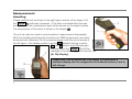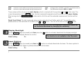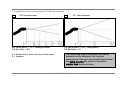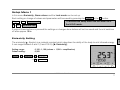
1
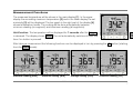
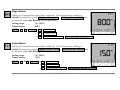
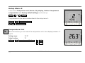
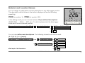
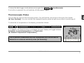
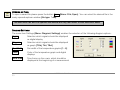
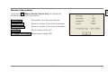
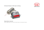
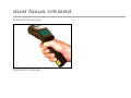
dual focus infrared ¯¯¯¯¯¯¯¯¯¯¯¯¯¯¯¯¯¯¯¯¯¯¯¯¯¯¯¯¯¯¯¯¯¯¯¯¯¯¯¯¯¯¯¯¯¯¯¯¯¯¯¯¯¯¯¯¯¯¯¯¯¯¯¯¯¯¯¯¯¯¯¯¯¯¯¯¯¯¯¯¯¯¯¯¯¯¯¯¯¯¯¯¯¯¯¯¯¯¯¯¯¯¯¯¯¯¯¯¯¯¯¯¯¯¯¯¯¯¯¯¯¯¯¯¯¯¯¯¯¯¯¯¯¯¯¯¯¯¯¯¯¯¯¯¯¯¯¯¯¯¯¯¯¯¯¯¯¯¯¯¯¯¯¯¯¯¯¯¯¯¯¯¯¯¯¯¯¯¯¯¯¯¯¯¯¯¯¯¯¯¯¯¯¯¯¯¯¯¯¯¯¯¯¯¯¯¯¯¯¯¯¯¯¯¯¯¯¯¯¯ Infrared Thermometer Operators manual CE-Conformity The product complies with the following standards: EMC: Safety Regulations: EN 61326-1 EN 61010-1:1993/ A2:1995 The product accomplishes the requirements of the EMC Directive 89/336/EEC and of the low-voltage directive 73/23/EEC. Scope of Supply dual focus infrared thermometer 2 batteries (type AA) t/c insertion probe USB interface cable software pouch hard case operators manual You will find the serial number on the unit. Always use this number when you contact the customer service concerning maintenance, additional order of components, spare parts or repairs. MEPDFI-MA-E2007-04-A 1 Thank you for choosing the dual focus infrared thermometer. Comments on this manual Read the manual carefully before the initial start-up. The producer reserves the right to change the herein described specifications in case of technical advance of the product. Orientation Important information and notes Icons for easy finding of chapters Operating elements on the unit │ Buttons in the software [► Reference to other chapters] ADJUSTABLE VALUES [Menu: Hint to menu items in the software] Readings on the unit display │ Readings in software screens Warranty Each single product passes through a quality process. Nevertheless, if failures occur please contact the customer service at once. The warranty period covers 24 months starting on the delivery date. After the warranty is expired the manufacturer guarantees additional 6 months warranty for all repaired or substituted product components. Warranty does not apply to electrical circuit breakers, primary batteries and damages, which result from misuse or neglect. The warranty also expires if you open the product. The manufacturer offers a 3 months warranty for rechargeable batteries. The manufacturer is not liable for consequential damage. If a failure occurs during the warranty period the product will be replaced, calibrated or repaired without further charges. The freight costs will be paid by the sender. The manufacturer reserves the right to exchange components of the product instead of repairing it. If the failure results from misuse or neglect the user has to pay for the repair. In that case you may ask for a cost estimate beforehand. MEPDFI-MA-E2007-04-A 2 Content Page Basic Operation Batteries User interface Display Measurement Handling Measurement Functions Display Backlight Laser Sighting Optics Setup Menu 1 Emissivity Setting High Alarm Low Alarm Long-Term Measurement (Lock Mode) Setup Menu 2 Temperature Unit Buzzer Flip-Display Ambient Temperature Compensation Reset Data Logger Storing Data 4 4 4 5 6 6 7 8 8 9 11 11 12 12 13 14 14 15 15 16 17 18 18 Page Material and Location Names Data Logger Recall Thermocouple Probe Software IRConnect Installation and Start Connection to the Computer Data Logger Functions Time Stamp Material and Location Names Digital Displays Diagram Functions Device Setup Device Information Specification Technical Data Factory Default Setting Troubleshooting Maintenance Principle of Operation Emissivity Appendix A – Emissivity Table Metals Appendix B – Emissivity Table Non Metals 19 20 21 22 22 22 24 25 25 26 27 32 33 34 34 36 36 37 38 39 41 42 MEPDFI-MA-E2007-04-A 3 Basic Operation Batteries To open the battery compartment gently press the cover lid on the left side of the handle in direction of the arrow (see picture). Insert the batteries (orientation as shown inside the compartment) and close the cover lid. If the batteries are low the battery symbol will appear in the display. Please exchange the batteries immediately if the symbol is flashing. Please do not use old and new batteries together. Please use only alkaline or rechargeable batteries [Type: Mignon AA, R6, UM3]. User interface 1 2 3 4 5 6 7 8 9 10 Precision glass optics Optics toggle switch SF/ CF Tripod mount Trigger Display Up and Down buttons Mode (I and II) buttons Handle and battery compartment USB interface t/c input MEPDFI-MA-E2007-04-A 4 Display Alarm activation High/ Low alarm Battery symbol Data logger mode Lock symbol Buzzer on LCD backlight Laser on Readings in the display 1 2 3 4 5 6 7 8 Status information Status information Upper display: Measurement functions (MIN-, MAX-, DIF-, AVG-indication), Data logger position Main display: IR-temperature and unit (°C/ °F) Lower display: HOLD, emissivity, probe temperature, Tamb-value, material and location name Assignment of buttons: Mode I I , Mode II II , Up Λ and Down V e Bar graph display Up and Down buttons Mode buttons MEPDFI-MA-E2007-04-A 5 Measurement Handling Please hold the unit as shown in the right figure and aim at the target. Pull the Trigger [1] and keep it pressed – if the laser is activated the true size and location of the measurement spot will be shown on the object surface. The temperature of the object is shown in the display [2]. The unit can also be used in vertical position (measurement downwards). With this handling small objects like electronic SMD components can easily be aimed and measured. For this purpose please hold the unit as shown in the left figure. If the display switch is set to Auto (default setting) or set to On, the I -button automatically gets the function of the Trigger [1] and the readings in the display [2] are turned by 180° [► Flip-Display]. Please note, that at vertical use (Flip mode) in context with a switched display also the assignment of the Mode buttons (I and II) will change. MEPDFI-MA-E2007-04-A 6 Measurement Functions The measured temperature will be shown in the main display [1]. In the upper display the according maximum temperature [2] and in the lower display the set emissivity [3] will be displayed. The bar graph in the right part of the display [4] shows temperature trends. The scaling will be done automatically between minimum reading (no segment) and maximum reading (all segments). Hold function: The temperature will be displayed for 7 seconds after the Trigger is released. The display shows HOLD. The unit automatically switches off after this time if no button is pressed. After taking a measurement the following functions can be displayed in turn by pressing the Λ -button (starting from the HOLD mode): Maximum reading [MAX] Minimum reading [MIN] Average reading [AVG] Difference reading [DIF] MEPDFI-MA-E2007-04-A 7 MAX: MIN: maximum value determined during measurement minimum value determined during measurement AVG: DIF: average value (related to duration of measurement) the difference between MIN and MAX These values will be shown in the main display, which is marked with the symbols > and < in this case. The current temperature (in the HOLD mode: the last measured temperature) will be shown in the upper display. After turning into the measure mode or after switch off of the unit the selected measurement function will be kept. Recall (Last Value) The last measured value remains stored in the LS after switch off. To recall this value please press (in the switched off condition) the I - or II -button. The unit will be set into the HOLD mode. In the emissivity menu the last measured temperature value can be corrected afterwards by changing the emissivity. Display Backlight Pull the Trigger (keep it pressed) and then press the I -button to activate/ deactivate the display backlight. The symbol in the display flashes to confirm. This function is not available in the Flip mode. Default setting: On Laser Sighting Pull the Trigger (keep it pressed) and then the II -button to activate/ deactivate the laser. The laser symbol in the display (only if the trigger is pulled) indicates the active laser. Default setting: On MEPDFI-MA-E2007-04-A 8 WARNING: Do not point the laser directly at the eyes of persons or animals! Do not stare into the laser beam. Avoid indirect exposure via reflective surfaces! Optics The unit has switchable optics. The two possible operating modes are indicated as SF mode (Standard Focus) and CF mode (Close Focus). In the SF mode (standard operating mode) objects ≥ 16mm can be measured. The measurement spot will be exactly marked with the patented crosshair laser, i.e. the real size and location of the spot is shown on the object – independently from the distance and with no optical offset (see right figure). In the CF mode objects ≥ 1mm (e.g. electronic components) can be measured. In this operating mode a two point laser shows the spot on the target. Both laser beams cross at the focus distance (62mm from front of housing) and indicate the minimum spot size at this distance (Diameter: 1mm). To switch between SF and CF mode please shift the Optic switch which is located beside the display, to the corresponding position (see right figure). MEPDFI-MA-E2007-04-A 9 The symbols on the housing have the following meaning: X SF/ Crosshair laser D:S (focus point) = 75:1/ 16mm@1200mm D:S (far field) = 36:1 D = Distance from front of the unit to the object S = Spotsize • CF/ Two point laser D:S (focus point) = 62:1/ 1mm@62mm D:S (far field) = 4:1 The measured area of the object (spot size) depends on the distance. For a correct measurement the spot size should have at least the same size like the object or should be smaller than that at all times. MEPDFI-MA-E2007-04-A 10 Setup Menu 1 In this menu Emissivity, Alarm values and the Lock mode can be set up. Each setting or change of values and parameters will be saved by pressing the Trigger or the I -button. Trigger⇒SAVE ⇒Measure mode I ⇒SAVE ⇒next menu item To activate the setup menu the unit must be in the HOLD mode. If none of these buttons is pressed the settings or changes done before will not be saved and the unit switches off after approx. 30 s. Emissivity Setting The emissivity (ε - Epsilon) is a material constant which describes the ability of the body to emit infrared energy. It can range between 0 and 1 (0 and 100 %) [► Emissivity]. Setting range: Default setting: 0,100...1,100 (values > 1,000 = amplification) 0,950 HOLD⇒ II ⇒ε flashes⇒ Λ ⇒ INCREASE ε ⇒ V ⇒ DECREASE ε MEPDFI-MA-E2007-04-A 11 High Alarm Setting of a temperature value (alarm setpoint). If the temperature reading is above this setpoint a visual display colour = red + flashing alarm symbol and an acoustic signal [► Buzzer] will be generated: Setting range: Default setting: -35...900°C 900°C HOLD⇒ II ⇒ I ⇒H flashes ⇒ Λ ⇒ INCREASE VALUE ⇒ V ⇒ DECREASE VALUE ⇒ II ⇒ACTIVATION/ DEACTIVATION ⇒alarm symbol [beside H] on/ off Low-Alarm Setting of a temperature value (alarm setpoint). If the temperature reading is below this setpoint a visual display colour = blue + flashing alarm symbol and an acoustic signal [► Buzzer] will be generated: Setting range: Default setting: -35...900°C -35°C HOLD⇒ II ⇒2x I ⇒L flashes ⇒ Λ ⇒ INCREASE VALUE ⇒ V ⇒ DECREASE VALUE ⇒ II ⇒ACTIVATION/ DEACTIVATION ⇒alarm symbol [beside L] on/ off MEPDFI-MA-E2007-04-A 12 Long-Term Measurement (Lock Mode) This function allows a continuous measurement without pulling the trigger for that time. The laser is only working if the trigger is pulled. Setting range: Default setting: On/ Off Off HOLD⇒ II ⇒3x I ⇒Lock symbol flashes ⇒ Λ ⇒ON/ OFF ⇒ V ⇒ON/ OFF after setting to On: 2x I ⇒HOLD+Lock⇒Trigger⇒starting Measurement mode+Lock or: Trigger⇒starting Measurement mode+Lock You can deactivate the Lock function in the same order, but starting from Measurement mode+Lock. The data logger functions are also available in the Lock mode [► Data Logger]. For a long-term temperature measurement of an object it is recommended to mount the unit on a tripod. MEPDFI-MA-E2007-04-A 13 Setup Menu 2 In this menu Temperature unit, Buzzer, Flip display, Ambient temperature compensation and Factory default settings can be set up. HOLD⇒ II ⇒4x I ⇒2. Menu The procedure is the same as described in the setup menu 1: Trigger⇒SAVE ⇒Measurement mode I ⇒SAVE ⇒next menu item Temperature Unit With this function you can switch the temperature unit in the display between °C und °F. Setting range: Default setting: °C/ °F °C 2. Menu⇒ II ⇒Temperature unit flashes ⇒ Λ ⇒°C/ °F ⇒ V ⇒°C/ °F MEPDFI-MA-E2007-04-A 14 Buzzer With this function the buzzer (acoustic alarm signal) can be switched on and off. Independent from this the key tone (confirmation by pressing Mode, Up and Down button) will remain On. Setting range: Default setting: On/ Off On 2. Menu⇒ II ⇒ I ⇒Buzzer symbol flashes ⇒ Λ ⇒ON/ OFF ⇒ V ⇒ON/ OFF Flip-Display The unit has a so called Flip display (turn around display). As the unit can be used in horizontal and in vertical position (preferably in combination with the CF mode), the ability to switch allows a comfortable operation in both positions. Setting range: Default setting: Auto/ Off/ On Auto 2. Menu⇒ II ⇒2x I ⇒current setting ⇒ Λ ⇒AUTO/ OFF/ ON ⇒ V ⇒AUTO/ OFF/ ON MEPDFI-MA-E2007-04-A 15 AUTO: OFF: ON: automatic position detection (by internal position sensor) and display switch according to the handling of the unit no switch (for reading at horizontal measurements) permanent switch (for reading at vertical measurements) If ON is activated the display will switch immediately (see the right picture). Please note, that in this context also the assignment of the Mode buttons (I und II) changes. Ambient Temperature Compensation In dependence on the emissivity value a certain amount of ambient radiation will be reflected from the object surface. To compensate this impact you can use this function to enter a temperature value for the ambient radiation [Tamb]: Setting range: Default setting: -35...900°C deactivated An activation of this function on the unit for the first time is only possible with the supplied software [► Device Setup]. 2. Menu⇒ II ⇒3x I ⇒Tamb ⇒ Λ ⇒ INCREASE VALUE ⇒ V ⇒ DECREASE VALUE ⇒ II ⇒ ACTIVATE/ DEACTIVATE MEPDFI-MA-E2007-04-A 16 If the Tamb-function is activated, the current set Tamb-value can be easily displayed as follows: Trigger+ Λ ⇒Toggle between Emissivity and Tamb in lower display If, in addition, a thermocouple probe is connected, the lower display will toggle between Emissivity, t/c probe temperature and Tamb value. [► Thermocouple Probe] Reset With this function the unit can be set back to the factory default values [► Factory Default Setting]. 2. Menu⇒ II ⇒3 or 41)x I ⇒RES⇒ II ⇒RES flashes ⇒ II ⇒RESET ⇒ I ⇒HOLD ⇒Trigger⇒Measure mode 1) depends on the status of Tamb function The stored values in the data logger will not be deleted with the reset function. MEPDFI-MA-E2007-04-A 17 Data Logger The unit has an internal data logger with a maximum capacity of 100 measurement protocols. Every protocol contains the following values: Position number [P 00...P 99], object temperature, MAX-, MIN-, AVG- and DIF-value, emissivity, probe temperature (if connected), material and location name Storing Data To store any data the unit must be in the HOLD mode. At first please take your measurement and after this release the Trigger: HOLD⇒ V ⇒Disc symbol + next free Pos. [Pxx] ⇒ Λ ⇒ INCREASE POS.-NO. ⇒ V ⇒ DECREASE POS.-NO. ⇒ I ⇒STORE1) ⇒HOLD 1) The storage will be confirmed with a double buzzer tone. If you pull the Trigger no storage will be made and the unit changes to the Measurement mode. If no button is pressed, also no storage will be made and the unit switches off after approx. 30 s. If the storage mode is started the next free position will automatically be shown. If you select an occupied position, the P flashes in the upper display. The storage function can also be executed after recall of the last value [► Recall (Last Value)]. MEPDFI-MA-E2007-04-A 18 Material and Location Names You can assign a 4-digit alpha numeric description to any data logger position. This description will be shown in the bottom display and has the following presetting: P000 (for position 1) – P099 (for position 100) In the editing mode you can choose between 20 pre-defined descriptions (SURF, ENG, ..., GLAS, ..., PVC, etc.). To do this please start the data logger mode and choose a desired position: Disc symbol + choosen position [Pxx]⇒ II ⇒description flashes ⇒ Λ ⇒SURF, ..., GLAS, ..., PVC, ... ⇒ V ⇒PVC, ..., GLAS, ..., SURF, ... ⇒ I ⇒SAVE You can also define own descriptions. The following character set can be used: [A...Z] [0...9] [-/<>] [empty] Disc symbol + choosen position [Pxx] ⇒2x II ⇒1. character flashes ⇒ Λ ⇒ CHANGE VALUE ⇒ V ⇒ CHANGE VALUE ⇒ II ⇒next character flashes ⇒ Λ ⇒ CHANGE VALUE ⇒ V ⇒ CHANGE VALUE ⇒ I ⇒SAVE after input of all characters: MEPDFI-MA-E2007-04-A 19 Data Logger Recall To recall a stored measurement protocol the unit must be set into the Measure mode: Trigger+ V [while keeping the trigger pressed]⇒Disc symbol flashes⇒P xx [starting with position 00] To switch between the data logger positions and different displays please proceed as follows: Upper display Main display P -1⇐ V ⇐P xx⇒ Λ ⇒P +1 a MAX e a MAX/ TObj e 1 2 TObj e ⇑ II e ⇓ TObj e ⇑ Λ ⇓ TObj/ MAX/ MIN/ AVG/ DIF 3 MEPDFI-MA-E2007-04-A 20 Lower display Examples a Material and location name e 1 ⇑ Emissivity II e ⇑ ⇓ Trigger+ Λ e ⇓ TExt [probe temperature] 4 2 3+4 To leave the data logger mode please press again the Trigger+ V simultaneously. If no button is pressed, the unit switches off after approx. 30 s. Thermocouple Probe The unit has an input for thermocouple probes. You will find the connection at the end of the handle [► User Interface]. You can connect the supplied insertion probe as well as any other t/c probe type K. To show the t/c temperature in the display, proceed as follows: Trigger+ Λ ⇒Toggle between T/C probe temperature and Emissivity [lower display] If, in addition, the Tamb-function is activated, the lower display will toggle between Emissivity, t/c probe temperature and Tamb value. [► Ambient Temperature Compensation] The t/c probe in combination with the thermometer unit can be used to determine an unknown emissivity value [► Emissivity]. MEPDFI-MA-E2007-04-A 21 Software IRConnect Installation and Start Main functions: Download of logger data Display and record of temperature trends Setup of parameters System requirements: Windows XP, 2000 USB interface Hard disc with at least 30 MByte free space At least 128 MByte RAM CD-ROM drive Insert the installation CD into the according drive on your computer. If the auto run option on your computer is activated the installation wizard will start automatically. Otherwise please start setup.exe on the CD-ROM. Follow the instructions of the wizard until the installation is finished. The installation wizard will place a launch icon on the desktop and in the start menu: [Start]\Programs\IRConnect. If you want to uninstall the software from your system please use the uninstall icon in the start menu. Connection to the Computer Please connect the unit with your computer by using the special USB adapter cable. After you have started the software and the communication has been established the status line (below the time axis) will show the following information: MEPDFI-MA-E2007-04-A 22 COMxx: Opened active COM port if a USB adapter cable is connected LS: Connected successful communication with the connected unit SF/ CF selected optics mode on the unit Please use for a connection between the unit and a computer only the supplied USB adapter cable, as otherwise there will be no function. The connection cable supplied is not a standard USB cable! As long as the unit is connected to your computer it will be powered via the USB interface. In this case operation is also possible if no batteries are inside the unit. At digital communication the unit display shows the HOLD – mode but the unit is measuring continuously and is sending temperature data via the interface to the computer [► Digital displays]. If you cannot establish a communication in spite of correct connection between unit and computer please choose the correct COM port under Menu: Setup\ Interface. If the USB adapter cable is connected this port is marked [Infrared Thermometer Adapter]: Language You can select the desired language under Menu: Setup\ Language. MEPDFI-MA-E2007-04-A 23 Data Logger Functions To download the logger data from the unit please press the Logger -button [Menu: Measurement\ Download logger data]. All data from the logger will be displayed in an extra window as a table: Columns in the logger table Index Date Time TObj TObj Min TObj Max TObj Avg TObj Diff. TInt TExt Hi-Alarm Lo-Alarm Eps Name serial number date of measurement time of measurement object temperature min. object temperature max. object temperature average object temperature difference between TObj Min and TObj Max internal unit temperature t/c temperature (if connected) High-Alarm value Low-Alarm value emissivity material or position name Logger temperatures, on which the set High-Alarm value has been exceeded, will be shown in the table red and bold. Logger temperatures, on which the set Low-Alarm value has been fallen below, will be shown in the table blue and bold. MEPDFI-MA-E2007-04-A 24 Save as... opens an explorer window to save the logger data on your computer [*.lgg] Open File... opens an explorer window to open existing logger files 1) Clear Logger... After confirmation of the security query all logger data inside the unit will be deleted [unit display shows: CLR]. The status line inside the data logger window (beneath the table) shows the location and file name of the current data. 1) The logger file can also be opened and edited with any text editor or Microsoft Excel. Time Stamp If you store data inside your thermometer for the first time (after insertion of the batteries), an internal timer will be started automatically. When connected to a computer the timer will be synchronized with the computer time. Thus, every logger entry is stored with date and time of the measurement. Please store the logger data on your computer before you change the batteries. Otherwise an exact assignment of the time of measurement is not possible (Restart of the timer). Material- and Location Names You can assign descriptions to each logger position by choosing between 20 predefined descriptions or defining own descriptions. The table of the predefined descriptions can be edited with the software. MEPDFI-MA-E2007-04-A 25 To open the table please press the Names button [Menu: Device\ Material and location names]. Then mark the entry which you would like to edit with the cursor and enter the desired name. The maximum length is four digits. The following character set can be used: [A...Z] [0...9] [-/<>] [Space]. If a wrong input is made (no character/ more than 4 characters/ invalid character) the position number in the table appears red and the table cannot be closed with OK . OK saves the changed table inside the unit Standard loads the standard table (factory default) in the connected unit Up moves the selected entry up Down moves the selected entry down Digital Displays If the unit is connected to your computer and you start the software, the current temperature TObj will be shown as digital display (top right). You can add additional displays for the internal temperature TInt and the temperature of a connected t/c probe TExt [Menu: View\ Digital displays]. MEPDFI-MA-E2007-04-A 26 The once selected displays will also appear after a restart of the software. The size can be changed if you put the mouse cursor on the line beneath the display and pull it down. The buttons of the tool bar will also be moved (depending on the display size). Diagram Functions STARTING THE MEASUREMENT To start a measurement, please press the Start button in the tool bar [Menu: Measurement\ Start]. Control elements of the time axis: 1 2 3 4 5 Scroll bar Zoom in (increase) Zoom out (decrease) Whole range H: Hold/ C: Continue MEPDFI-MA-E2007-04-A 27 Any activation of a control element of the time axis will stop the further actualization of the measurement graph. The measurement itself continues in the background. To return to the current measurement graph please press the Pause button [Menu: Measurement\ Pause] or C. During the stopped status any parts of the diagram can be selected with the Time scroll bar. With the zoom inbutton + these parts can be stretched (enlarged) and with the zoom out-button – clinched (minimized). SCALING OF THE TEMPERATURE AXIS With global scaling the temperature range of the diagram will automatically be adapted to the respective peak values. The range will remain as set during the whole measurement. Control elements of the temperature axis: 1 2 3 4 5 6 Global auto scaling Local auto scaling Scroll bar Zoom in (increase) Zoom out (decrease) Whole range With local scaling the temperature range of the diagram will be adapted dynamically to the respective peak values. After the respective peak has left the diagram in the further process of the measurement, the range will be readapted. This option enables an optimum display of the temperature graph. A manual scaling can be done at any time using the control elements of the temperature axis. Activation of the desired option: Control elements (temperature axis) or [Menu: Diagram]. MEPDFI-MA-E2007-04-A 28 STOP MEASUREMENT To stop the current measurement please press the Stop button [Menu: Measurement\ Stop]. The Save button [Menu: File\ Save as] opens an explorer window to select destination and file name [file type: *.dat]. SAVING OF DATA The menu item options [Menu: Setup\ Options] enables the following settings for data protection: Warning if unsaved data exist if activated, each Stop and new Start will be followed by the query: There is unsaved Data. Save now? [Default setting: activated] Force data saving after „stop“ if activated, after each Stop an explorer window for saving the data will be opened automatically. Decimal separator System uses the computer system based separator for saving the data. If you want to use a user defined (which may be helpful for further use of the data files with other applications) you can enter the desired separator in the according field. If none of both options is activated, a new measurement will be started after termination of one measurement and pressing of the Start button. In this case the former data are deleted! MEPDFI-MA-E2007-04-A 29 OPENING OF FILES To open a saved file please press the button Open [Menu: File\ Open]. You can select the desired file in the newly opened explorer window [file type: *.dat]. The data files can also be opened and edited with any text editor or with Microsoft Excel. DIAGRAM SETTINGS The menu item Settings [Menu: Diagram\ Settings] enables the selection of the following diagram options: Digital Selection which signals should be displayed as digital display Diagram Selection which signals should be displayed as graph [TObj, TInt, TExt] Pen Width Pen width of the temperature graphs [1...5] Color Color of the temperature graph and digital displays Initial time Time frame on the x-axis, which should be displayed at the beginning of a measurement MEPDFI-MA-E2007-04-A 30 MEASUREMENT CONFIGURATION The menu item [Menu: Measurement\ Settings] opens the following dialog: Max. data count Limitation of the maximum number of data values – when achieved the measurement will be stopped Memory Memory, calculated from the max data count value (will also be displayed in the status line) Recording interval Time between single data [1ms...10s] Recording time maximum time of measurement, calculated from Max data count and Recording interval A change of the parameter Max data count will have influence on the Memory and Recording time. A change of the parameter Recording interval will have influence on the Recording time only. MEPDFI-MA-E2007-04-A 31 Device Setup The button Setup [Menu: Device\ Setup] opens a dialog window for setting up the following parameters of the unit: Emissivity High alarm Low alarm Ext. Ambient Temp. Temperature unit Backlight Laser Buzzer Lock mode Flip mode The first activation of Ext. Ambient Temp. will initiate this feature inside the unit. From this time the feature will appear in the Setup Menu 2 on the unit, also if deactivated again in the device setup [► Ambient Temperature Compensation]. A reset of the unit to the factory default values [► Reset] will delete the display of this function during operation [Setup Menu 2]. To load the factory default settings into the unit please press the Factory Default button (same functionality as ► Reset). An additional query avoids a reset of the unit by mistake. A change of parameters will be taken over from the connected unit immediately and vice versa. MEPDFI-MA-E2007-04-A 32 Device Information The button Info [Menu: Device\ Device Info] will display the following unit-specific information: Device type Description from the manufacturer Firmware Rev. Revision number of the internal software Hardware Rev. Revision number of the internal hardware Serial No. Serial number of the unit IR Temperature range Measurement range (IR) MEPDFI-MA-E2007-04-A 33 Specification Technical Data Temperature range IR: Temperature range probe: Temperature unit: Spectral range: Optical resolution: Minimum spot size: Temperature resolution: -35…900°C (-30…1650°F) -35…900°C (-30…1650°F) °C/ °F (switchable) 8…14µm 75:1 (16mm@1200mm/ 90% energy) switchable to CF (close focus): 1mm@62mm/ 90% energy 1mm@62mm (CF mode) 0,1°C Accuracy IR 1): Accuracy t/c input: Repeatability: Temperature coefficient 2): Response time: ±0,75°C or ±0,75% of reading (whichever is greater) ±0,75°C or ±1,0% of reading (whichever is greater) ±0,5°C or ±0,5% of reading (whichever is greater) ±0,05K/K or ±0,05%/K (whichever is greater) 150 ms (95% signal) Display: LCD Flip Display with backlight (horizontal and vertical viewing directions controlled by position sensor) green and alarm colours (red/ blue) auto scaling <1mW, class II, 630-650 nm SF: patented crosshair laser (size of crosshairs = spot size@ any distance) CF: two point laser (laser dot size = spot size@ focus distance) Display backlight: Bar graph display: Laser: MEPDFI-MA-E2007-04-A 34 Measurement functions: Alarm functions: Emissivity/ Gain: Interface: Input: Data Logger: Software: Power supply: MAX, MIN, DIF, AVG, HOLD High and Low alarm, audible and visual 0,100…1,100 (adjustable) USB t/c type K 100 measurement protocols with time stamps, 4 digit material and location names (editable) IRConnect oscilloscope software, 20 readings per second Ambient temperature: Storage temperature: Relative humidity: EMI: Weight: 2xAA (Mignon Alkaline) batteries or via USB cable (if connected to a PC) 5h (operating with laser and backlight 50% on) 10h (operating with laser and no backlight) 25h (operating without laser and backlight) 0 – 50°C -30…65°C (without batteries) 10 – 95%, non condensing 89/336/EWG 420 g Vibration: Shock: Tripod mounting: IEC 68-2-6: 3G, 11 – 200Hz, any axis IEC 68-2-27: 50G, 11ms, any axis ¼ - 20 UNC Battery life time: 1) 2) at 23°C ambient temperature and object temperature: 20…900°C below 20°C and above 30°C MEPDFI-MA-E2007-04-A 35 Factory default settings The unit has the following presettings at the time of delivery: Emissivity: Optics: High alarm: Low alarm: Temperature unit: 0,950 SF 900°C/ deactivated -35°C/ deactivated °C Lock: Buzzer: Laser: Display backlight: Display turn: Off On On On Auto The Reset function will set the unit back to these default values (exception: optics). Troubleshooting Display Problem Action temperature reading: LLLL object temperature below measurement range choose target within measuring range temperature reading: HHHH object temperature above measurement range choose target within measuring range battery symbol is on or flashing low batteries check/ replace batteries blank display empty batteries check/ replace batteries immediately laser does not work low batteries/ laser deactivated see above activate the laser MEPDFI-MA-E2007-04-A 36 Maintenance Lens cleaning: Blow off loose particles using clean compressed air. The lens surface can be cleaned with a soft, humid tissue moistened with water or a water based glass cleaner. Cleaning the housing: To clean the exterior housing, use a humid tissue (wetted with water or a mild commercial cleaner). PLEASE NOTE: Never use cleaning compounds which contain solvents (neither for the lens nor for the housing). CAUTIONS: Avoid static electricity, arc welders, and induction heaters. Keep away from very strong EMF (electromagnetic fields). Don’t leave the unit on or near objects of high temperature. WARNING: Do not touch live voltage with Avoid abrupt changes in ambient temperature. If this occurs, the contact probe. allow 20 minutes for thermal stabilization before the use to prevent the possibility of inaccurate temperature readings. In case of problems or questions, which may arise when you use the unit, please contact our service department. The customer service staff will support you with questions concerning the optimization of the work with the infrared thermometer, calibration procedures or with repairs. MEPDFI-MA-E2007-04-A 37 Principle of Operation Basics of Infrared Thermometry Depending on the temperature each object emits a certain amount of infrared radiation. A change in the temperature of the object is accompanied by a change in the intensity of the radiation. For the measurement of “thermal radiation” infrared thermometry uses a wave-length ranging between 1 µ and 20 µm. The intensity of the emitted radiation depends on the material. This material contingent constant is described with the help of the emissivity which is a known value for most materials (see enclosed table emissivity). Infrared thermometers are optoelectronic sensors. They calculate the surface temperature on the basis of the emitted infrared radiation from an object. The most important feature of infrared thermometers is that they enable the user to measure objects contactless. Consequently, these products help to measure the temperature of inaccessible or moving objects without difficulties. Infrared thermometers basically consist of the following components: lens spectral filter detector electronics (amplifier/ linearization/ signal processing) The specifications of the lens decisively determine the optical path of the infrared thermometer, which is characterized by the ratio Distance-to-Spot-size. The spectral filter selects the wavelength range, which is relevant for the temperature measurement. The detector in cooperation with the processing electronics transforms the emitted infrared radiation into electrical signals. MEPDFI-MA-E2007-04-A 38 Emissivity Definition The intensity of infrared radiation, which is emitted by each body, depends on the temperature as well as on the radiation features of the surface material of the measuring object. The emissivity (ε – Epsilon) is used as a material constant factor to describe the ability of the body to emit infrared energy. It can range between 0 and 100 %. A “blackbody” is the ideal radiation source with an emissivity of 1,0 whereas a mirror shows an emissivity of 0,1. If the emissivity chosen is too high, the infrared thermometer may display a temperature value which is much lower than the real temperature – assuming the measuring object is warmer than its surroundings. A low emissivity (reflective surfaces) carries the risk of inaccurate measuring results by interfering infrared radiation emitted by background objects (flames, heating systems, chamottes). To minimize measuring errors in such cases, the handling should be performed very carefully and the unit should be protected against reflecting radiation sources. Determination of unknown Emissivities ► First, determine the actual temperature of the measuring object with a thermocouple or contact sensor. Secondly, measure the temperature with the infrared thermometer and modify the emissivity until the displayed result corresponds to the actual temperature. ► If you monitor temperatures of up to 260 °C you may place a special plastic sticker onto the measuring object, which covers it completely. Now set the emissivity to 0,95 and take the temperature of the sticker. Afterwards, determine the temperature of the adjacent area on the measuring object and adjust the emissivity according to the value of the temperature of the sticker. MEPDFI-MA-E2007-04-A 39 ► Cove a part of the surface of the measuring object with black, flat paint with an emissivity of 0,98. Adjust the emissivity of your infrared thermometer to 0,98 and take the temperature of the colored surface. Afterwards, determine the temperature of a directly adjacent area and modify the emissivity until the measured value corresponds to the temperature of the colored surface. Characteristic Emissivities In case none of the methods mentioned above help to determine the emissivity you may use the emissivity tables (Appendix A and B). These are average values, only. The actual emissivity of a material depends on the following factors: temperature measuring angle geometry of the surface thickness of the material constitution of the surface (polished, oxidized, rough, sandblast) spectral range of the measurement transmissivity (e.g. with thin films) MEPDFI-MA-E2007-04-A 40 Appendix A – Emissivity Table Metals Material Aluminium Brass Copper Chrome Gold Haynes Inconel Iron Iron, casted Lead non oxidized polished roughened oxidized polished roughened oxidized polished roughened oxidized alloy electro polished sandblast oxidized non oxidized rusted oxidized forged, blunt non oxidized oxidized polished typical Emissivity 0,02-0,1 0,02-0,1 0,1-0,3 0,2-0,4 0,01-0,05 0,3 0,5 0,03 0,05-0,1 0,4-0,8 0,02-0,2 0,01-0,1 0,3-0,8 0,15 0,3-0,6 0,7-0,95 0,05-0,2 0,5-0,7 0,5-0,9 0,9 0,2 0,6-0,95 0,05-0,1 Material Lead Magnesium Mercury Molybdenum Monel (Ni-Cu) Nickel Platinum Silver Steel Tin Titanium Wolfram Zinc roughened oxidized non oxidized oxidized electrolytic oxidized black polished plate rustless heavy plate cold-rolled oxidized non oxidized polished oxidized polished polished oxidized typical Emissivity 0,4 0,2-0,6 0,02-0,1 0,05-0,15 0,1 0,2-0,6 0,1-0,14 0,05-0,15 0,2-0,5 0,9 0,02 0,1 0,1-0,8 0,4-0,6 0,7-0,9 0,7-0,9 0,05 0,05-0,2 0,5-0,6 0,03-0,1 0,02 0,1 MEPDFI-MA-E2007-04-A 41 Appendix B – Emissivity Table Non Metals Material Asbestos Asphalt Basalt Carbon Carborundum Ceramic Concrete Glass Grit Gypsum Ice Limestone Paint Paper Plastic >50 µm Rubber Sand Snow Soil Textiles Water Wood non oxidized graphite non alkaline any color non transparent natural typical Emissivity 0,95 0,95 0,7 0,8-0,9 0,7-0,8 0,9 0,95 0,95 0,85 0,95 0,8-0,95 0,98 0,98 0,9-0,95 0,95 0,95 0,95 0,9 0,9 0,9-0,98 0,95 0,93 0,9-0,95 MEPDFI-MA-E2007-04-A 42