1
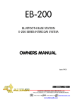
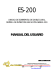
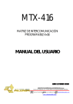
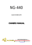
ELECTRA
E-3
PROFESSIONAL
LIVE
CONSOLE
OWNERS MANUAL
RELEASE 1.0 WEB
AUDIO ELECTRONICS DESIGN
EQUIPOS EUROPEOS ELECTRÓNICOS, S.A.L
Avda. de la Industria, 50. 28760 TRES CANTOS-MADRID (SPAIN).
34-91-761 65 80
34-91-804 43 58
www.altairaudio.com
[email protected]
ALTAIR ELECTRA E-3
OWNERS MANUAL RELEASE 1.0
Professional Live Console
19 AUX MONITOR / IN-EAR
9 AUX mono (A1-A8,C)
5 AUX stereo (A9-A16, L-R)
MAIN FEATURES
FRAMES: 32/40/48 Mono + 4 Stereo.
16 AUX Sends (8 Mono+4 Stereo/8 Mono).
MIX BUSES: 8 GRP + 3 MIX (LCR).
16 EQ+DYNAMICS 24 bit DSP based (AUX outputs).
8 VCA Motorised Masters + 100 Scene&Mute Presets.
Simultaneous AUX/GRP Functionality: FOH/Monitor/Both.
16x8 MATRIX, under digital control for a clear console layout.
Balanced, Dual Jack Insert points.
Super EQ on Inputs (H&L vari. Freq+Shl/Peak,2 Mids full parametric
Cable Test function on each input.
VCA Solo in AFL/PFL mode. Now, you can listen the VCA group.
Combo (TM) Input Connectors
FULL Meter Bridge: LCD+24 x 20 led Bars + 4 Vu-Meters.
Robust Power Supply with redundant power supply system.
2
ALTAIR ELECTRA E-3
Mono Input
MIC AMP
High performance Mic
amplifier. BB (TM)
EQ-Section: +-15 dB
HF- Peaking/Shelving
1Khz-20Khz
MID1: Full parametric
400Hz-8Khz // Q-0,5-3
MID2: Full parametric
100Hz-2Khz // Q-0,5-3
LF- Peaking/Shelving
30 Hz-600 Hz
HPF: Variable Freq:
20Hz-400Hz // 12 dB/oct
OWNERS MANUAL RELEASE 1.0
AUX 9-10
Dual concentric Pots.
Normally configured as
mono, can be changed
to stereo pairs from
GRP/AUX Modules.
Switchable PRE-POST in
pairs.
AUX 11-12, 13-14, 15-16
Same as above
LCR
Dual concentric LCR
knob and LCR
switch with
independent centre
send and LR-C
image control.
Subgroups assigns
can routed pre or
post PAN Pot.
VUMETER
Eight segment
vumeter and peak
leds.
INSERT POINTS
CPU CANCEL
Electronically
balanced Send &
Return.
Nominal level 0 dBu.
Automation cancel
security switch to prevent
cpu abnormal
operations.
SOLO SWITCH
XLR/JACK COMBO
Mic/Line Input.
Both connectors in
the assembly are
paralleled. There is
not phantom in the
Jack. Set the PAD
and Input Gain to
adapt Line levels.
PFL/AFL function
depending of selection
on MASTER module.
Enables cable tester
when only one channel is
selected. The test must
be done with moderate
input level. Best results
are obtained when PAD
is in the off position.
Used as VCA&MUTE
assign switches.
3
ALTAIR ELECTRA E-3
OWNERS MANUAL RELEASE 1.0
Stereo Input
Each console is equipped with
four Stereo channels as
standard.
MIC AMPS
High performance Mic
amplifiers. BB (TM)
AUX 1-8
Mono (L+R) Sends, can be
switched to Stereo in pairs,
Aux 1 sends L, 2 sends R...
Switchable PRE-POST in
pairs.
AUX 9-16
EQ-Section: +-15 dB
HF: Shelving, 1Khz-20Khz
MID1: Full parametric
400Hz-8Khz // Q-0,5-3
MID2: Full parametric
100Hz-2Khz // Q-0,5-3
LF- Shelving, 30 Hz-600 Hz
HPF: Fixed Freq:
60Hz // 12 dB/oct
Dual concentric Pots.
Normally configured as
mono, can be changed to
stereo pairs from GRP/AUX
Modules.
Switchable PRE-POST in
pairs.
LCR
Dual concentric
LR-C knob with
independent Centre
send and LR Bal control.
GROUP ASSIGN
Eight Groups can be
made in stereo pairs.
PAN enables post Bal
control.
INSERT POINTS
STEREO VUMETER
Electronically
balanced Send &
Return.
Nominal level 0 dBu.
Eight segment
vumeter and
multipoint peak in
both L&R.
XLR/JACK COMBO
Mic/Line Input.
Both connectors in
the assembly are
paralleled. There is
not phantom in the
Jack. Set the PAD
and Input Gain to
adapt Line levels.
CPU CANCEL
Automation cancel
security switch to prevent
cpu abnormal
operations.
SOLO SWITCH
PFL/AFL function
depending of selection
on MASTER module.
Used as VCA&MUTE
assign switches.
4
ALTAIR ELECTRA E-3
OWNERS MANUAL RELEASE 1.0
Grp1-8/Aux 1-8
GROUP SENDS
To LR and C Busses.
TB
Selects the Talkback signal
into this module.
INS
Enables the Insert
connection to take place
ON SWITCH
Automated on/off switch.
SAFE MODE: Press and
hold this switch for a few
seconds.
SOLO (AFL ó PFL)
Automated SOLO
switch.
MUTE assign mode:
Press this button to
assign the group to
the MASTER MUTE.
EQ FLIP. Flips the
EQ/DYN section to
the GRP
EQ on/off
This switch enables the
auxiliary 1 to 16 digital
equalisation to take
place.
ON SWITCH
Automated on/off switch.
SAFE MODE: Press and
hold this switch for a few
seconds.
BUS INJECT
To link two
consoles.
INSERT
Double insert point.
Balanced jack.
Nominal level 0 dBu.
SOLO (AFL ó PFL)
Automated SOLO
switch.
MUTE assign mode:
Press this button to
assign the auxiliary to
the MASTER MUTE.
5
ALTAIR ELECTRA E-3
OWNERS MANUAL RELEASE 1.0
Matrix1-8/Aux9-16
SELECT SWITCH
Selects the matrix layer on vca panel
to assign the matrix sources: Groups
Gpr1-Gpr8, Aux 1-4, LCR and external
input.
TB
Selects the Talkback
signal into this module.
INS
Enables the Insert
connection to take place
ON SWITCH
Automated on/off switch.
SAFE MODE: Press and
hold this switch for a few
seconds.
SOLO (AFL ó PFL)
Automated SOLO switch.
MUTE assign mode: Press this
button to assign the matrix to the
MASTER MUTE.
GLOBAL MONO/STEREO SWITCH
This switch configures the auxiliaries
9/10 to 15/16 in mono or stereo pairs.
EQ FLIP. Flip the
EQ/DYN section to the
MTX.
EQ on/off
This switch enables the
auxiliary 1 to 16 digital
equalisation to take place.
ON SWITCH
Automated on/off switch.
When STO pair is selected,
both ON switches are
linked automatically.
SAFE MODE: Press and hold
this switch for a while.
SOLO (AFL ó PFL)
Automated SOLO switch.
When STO pair is selected,
both SOLO switches are
linked automatically,
allowing stereo AFL
MUTE assign mode: Press
this button to assign the
auxiliary to the MASTER
MUTE in Mute Edit mode.
6
ALTAIR ELECTRA E-3
Master Module
STEREO INPUT
Stereo general purpose Line
input incorporating HF/LF Eq
LR/C sends and SOLO. L and
R switches allows mono input
Input Gain: -18 to +7 dB
L,R,C BUS CLIP
Bus overflow clip
indicators.
PFL ADJ.
Allows level balance
between SOLO PFL and
AFL in the Monitor and
Phones outputs
OWNERS MANUAL RELEASE 1.0
TALKBACK
OSCILLATOR
Sine, pink noise and test signal
BEAT. This BEAT is a Drum
sample, very useful for room
acoustics, reverb set up,
loudspeakers check or Delay
Tower alignment.
SOLO SYSTEM
S.I.P. Solo in place.
Exclusive SOLO: Toggles
between individual or SOLO
group selections. Set it to
Exclusive when using the Cable
Test.
SOLO CLEAR
Clear all selected Solos.
LR, C Signal Select
Sets the default cue
signal when no SOLO is
selected.
SOLO MODE: Selects global
mono PFL or Stereo AFL mode on
ll SOLO i h i h
l
MASTER B
MONITOR/WEDGE
Stereo Monitor level
control. Allows easy
control of a Wedge in
monitor applications.
Additional Master output.
Can be set PRE or POST
main MASTER.
Very useful to check the
mono compatibility of the
Stereo LR output using
SOLO in AFL and PFL.
PHONES LEVEL
GRP/MTX Meter selector
A pair of paralleled Phones
output located under the
panel for ease phones cord
handling.
Right hand meterbridge
bargraph selection.
TB
Talkback Signal assignment to
LR or C buses
INS
Enables the Insert connection
to take place.
LRC
Main Master L-R-C faders.
ALPS 100 mm K series.
7
ALTAIR ELECTRA E-3
OWNERS MANUAL RELEASE 1.0
8
VCA/AUTOMATION Section
SEL Switches SELects the Auxiliary output to be controlled in the EQ/DYN layout. Motorised VCA faders jump to
the stored EQ positions. Rotary Encoders 1-8 and associated lamps show the relative Frequency around initial
Console pre-set points.
F/Q Toggles to Q adjustment in this band. 1 and 8 filter bands incorporate Shelving filter mode.
This layout shows a simple 8 bands graphic-EQ to most users allowing full parametric 8 points EQ with notch
capabilities if needed. Initial centre Freq. and bandwidth Q are chosen carefully for easy operation.
Dynamics Blocks: Selected Out Dynamics settings.
VCA Moto-Faders: Normally used as VCA control, serves as EQ and Matrix sends control.
When MATRIX Page is selected, a full view of the SELected 1-8 Matrix output mix shows the 16 Matrix sends:
faders jumps to AUX 1-4, C (centre), L, R and EXT in and the Encoders/lamps indicates GRP 1-8.
MUTE This 8 switches Mutes the associated 1-8 VCA groups. The effect is the same as you turn down the
associated VCA fader to the minimum or -oo position. The action of this switch can be selected as instantaneous
or under confirmation to avoid inadvertent operation. See the UTIL>SECURITY menu explanations below to setup. It is possible a quick access by double-clicking it.
SOLO This is a powerful listen VCA solo that calls for a mix of all the assigned channels from that VCA group.
When selected a VCA solo, the assigned channel’s SOLOs will light to indicate what are you soloing.
The listen of this solo can be selected to be AFL or PFL depending of the global SOLO setting.
This function can help the operator to balance the individual levels of the channels of each different VCA groups,
and to double check real members of that group of signals.
ALTAIR ELECTRA E-3
OWNERS MANUAL RELEASE 1.0
9
OPERATION MODES. LAYER SELECTION
VCA Selects the VCA layer. The 8 motorized Faders shows the VCA Fader level. The Fader position is
stored and Recalled as part of the Scene memory. In this mode, the assign leds on each input channel
shows the VCA group assign.
MUTES Selects the Mute layer. The Fader position remains as in VCA control. In this mode, assign
leds on each input channel shows the assigned MUTE group.
EQ Selects the Equalization layer. Fader position shows the level of the 8 frequency bands of the
SELected Auxiliary Out. You can edit it in real time or in preview mode.
MATRIX In this mode, you can adjust the Matrix sources (inputs) of the SELected Matrix Master 1-8.
To avoid possible confusion between LAYERS, all the switches and function leds are color-coded.
Moreover, you can customize the Layers in the configuration Menu to enable only the ones used in the
current show. As an example, in studio production or FOH operation, you only need VCA and MUTES.
On the other hand, Theatre or Monitor applications need the EQ and MTX enabled normally.
EDIT MODES.
VCA/MUTES Edit.
This is done by selecting the VCA or MUTE layer, EDIT key, and VCA or Master Mute switch and SOLO
assign keys on the input channels. All the sequence is intuitive and is followed by indications on the
Main Screen and associated key lamps. It is possible to Edit with the parameter Wheel and cursors as
well.
VCA EDIT
-Press VCA key to select VCA layer
-Press Edit key
-Select VCA group 1 to 8 with the SOLO (VCA assign) switches on the VCA Fader panel.
-Select or unselect the input channel you want to assign by pressing the SOLO (VCA assign).
-Press again Edit key to finish.
MUTE EDIT
-Press MUTES key to select MUTE layer.
-Press Edit key
-Select MUTE group 1 to 8 with the MASTER MUTE switches on the VCA Fader panel.
-Select or unselect the input channel or AUX/GRP/MTX you want to assign by pressing the SOLO (MUTE
assign) in this module.
-Press again Edit key to finish.
ALTAIR ELECTRA E-3
OWNERS MANUAL RELEASE 1.0
10
POWER SUPPLY
FRONT PANNEL
INDICATORS.
+17, -17 Volts DC analog rails
+12 Volts logic, Lamps and Fans.
+48 Volts for Phantom Supply
GLOBAL AC Indicates AC presence and normal operation.
GLOBAL DC Monitors all the DC rails and indicates that all the outputs are working correctly in terms of
voltage/current specifications. This indicator also monitors the correct internal fan operation.
REDUNDANT CONNECTION
The power supply incorporates 2 power outlet connections: LINK and DC OUT. Connect the power supply #1 LINK
connector to the power supply #2 LINK connector with the included 40 cm link power cable.
When you switch on any of the power supplies, all the 4 voltage rail indicators in both power supplies will light
indicating presence of D.C. power onto the connector side.
REAR PANNEL
DC WIRING
SPECIFICATIONS
-Input voltage range: 90 to 260 VAC /50-60 Hz. Universal Voltage. Auto-range.
-Power Factor: 0,99 Meets EN61000-3-2 in terms of Harmonic Distortion
-Inrush Current 40 A peak max
-Power output +17/-17 VDC/11 Amp max
-12 VDC/10 Amp max
-48 VDC/1Amp max
-Radiated EMI: Meets CISPR 22, EN55022 Level B
-Leakge current: 2.0 mA max @240 VAC
-Ambient Temperature Range: 0ºC to 50ºC max
-Dimensions/Weight :2U height (89mmX482mmX260mm) /5Kg un-packed.
ALTAIR ELECTRA E-3
OWNERS MANUAL RELEASE 1.0
Console Dimensions (32+4 CH shown)
1624 mm - (32+4 channels)
1884 mm - (40+4 channels)
2140 mm - (48+4 channels)
11
ALTAIR ELECTRA E-3
12
OWNERS MANUAL RELEASE 1.0
TECHNICAL SPECIFICATIONS
HARMONIC DISTORTION: Less than 0,05% from 20 Hz to 20 KHz with -30 dBu input and +4dBu
output @ 600 Ohm.
FREQUENCY RESPONSE: 20 Hz - 20 KHz (-2, -0.5 dB), microphone input, 35 dB gain.
128 dBu (E.I.N.), -82 dBu in the L-R output with master to unity gain & 24
NOISE:
channels assigned.
82 dB to L-R, 92 dB to L—R from one group, 82 dB to group & 84 dB to
MIC GAIN:
auxiliary output.
MIC/LINE GAIN (PAD on): 52 dB to the L-R output, 52 dB to the group output, 54 dB to aux. output.
-85 dB between groups (1 KHz), -85 dB between adjacent channels (1 KHz).
CROSSTALK:
+/- 15 dB HF - Peaking/Shelving ( only SHV on stereo ) 1 KHz — 20 KHz.
INPUT CH. EQUALISER:
+/- 15 dB MID1 - Full parametric 400 Hz — 8 KHz // Q: 0,5 - 3.
+/- 15 dB MID2 - Full parametric 100 Hz — 2 KHz // Q: 0,5 — 3.
+/- 15 dB LF
- Peaking/Shelving ( only SHV on stereo ) 30 Hz — 600 Hz.
Continuously variable, 12 dB per octave 20 Hz - 400 Hz. Fixed 60 Hz on sto.
INPUT CHANNEL HPF:
8 bands full parametric/shelving digital equaliser.
AUXILIARY EQUALISER:
+15/-30 dB; 20 Hz — 20 KHz // Q: 0,1 —10
24 bargraph (16 points) - 4 moving coil (L-C-R-PFL) - Graphic colour lcd
VUMETERS:
display.
+17, -17, +12, +48 VDC 600 Watts. Connector for redundancy.
POWER SUPPLY:
Input channel transformers. Lamps. Flight Case.
OPTIONS:
Output transformer.
Input channel equalizer graphs:
Audio Precision
MID 1
EQ
ELECTRA E-3
02/20/03 12:36:33
Audio Precision
ELECTRA E-3
02/20/03 12:31:25
+17.5
+15
+15
+12.5
+12.5
+10
+10
+7.5
+7.5
+5
+5
+2.5
+0
-2.5
A
EQ
+20
+20
+17.5
d
B
r
MID 2
d
B
r
+2.5
A
-2.5
-7.5
-7.5
-10
-10
-12.5
-12.5
-15
-15
-17.5
-17.5
-20
20
+0
-5
-5
-20
20
50
100
200
500
1k
2k
5k
10k
50
100
200
20k
Audio Precision
HF
EQ
ELECTRA E-3
02/20/03 12:54:28
Audio Precision
+20
+20
+17.5
+17.5
+15
+15
+12.5
+12.5
+10
+10
A
-2.5
+0
d
B
r
+2.5
A
-2.5
5k
10k
20k
LF
EQ
ELECTRA E-3
02/20/03 12:49:32
+0
-5
-5
-7.5
-7.5
-10
-10
-12.5
-12.5
-15
-15
-17.5
-20
20
2k
+5
+5
+2.5
1k
+7.5
+7.5
d
B
r
500
Hz
Hz
-17.5
50
100
200
500
Hz
1k
2k
5k
10k
20k
-20
20
50
100
200
500
1k
2k
5k
10k
20k
Hz
AUDIO ELECTRONICS DESIGN
Avda. de la Industria, 50. 28760 TRES CANTOS-MADRID (SPAIN).
EQUIPOS EUROPEOS ELECTRÓNICOS, S.A.L
TEL.:34-91-761 65 80 FAX.: 34-91-804 43 58 [email protected]
www.altairaudio.com