1
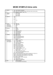
Supplementary Documentation for
Operating Instructions
Hot Runner Control Cabinets
Series HR & HRD
Rev. 2.00.04
02/2009
The Zone Displays – Status and Error Messages
Display
German
Display
English
Rectification of the error in case of an
error message
Stb
FSt
Afb
Id
Fb
MA
CoU
StA
Id
FP
tCb
Sensor reverse voltage
FuS
FuS
Fuse alarm only for HRD
Err
Err
Data error in channel data
AL
AL
Maximum temperature / upper
measuring range limit exceeded
IF
IF
Error message “No heating current
is measured” during the
identification phase
SbY
SbY
bSt
bSt
Temperature reduction / Standby
active
Temperature increase / Boost
active
Meaning
Regulation mode
Zone in pilot regulation
Start-up mode active
Identification active
Sensor failure
Sensors defective.
In order to be able to keep operating the
zones in the regular mode, the sensors
need to be exchanged immediately;
otherwise the zones in the Regulation
mode or in the pilot regulation zone will
switch and continue working with defective
sensors.
Sensor connections are confused.
Swap over the two sensor wires + and – of
the corresponding zones.
Wiring error. The error is saved and needs
to be acknowledged.
1/6
Change to the parameter level and change
a value, then acknowledge the change.
The error message will then disappear.
Alternatively, enter code number 950.
The actual value of the zones has
exceeded the measuring range limit or the
maximum temperature (500°C). The
heating output for the corresponding zone
is switch off. The error is saved and needs
to be acknowledged.
If the error comes before the error
message I-, the power unit may be
defective. Please exchange.
Likewise, errors in the sensors are
possible. Please observe the actual value.
Please contact the supplier for a quick
remedy.
The controller switches off the zones and
checks in cycles whether a heating current
can be measured or not.
Reason for error: Fuse failure, heater
failure or the connection cable to the
heater is defective.
Supplementary Documentation for
Operating Instructions
Hot Runner Control Cabinets
Series HR & HRD
Rev. 2.00.04
02/2009
Display
German
Display
English
dIA
Ar
Ar.
dIA
Ar
Ar.
I-
I-
Meaning
Diagnosis function active
Automatic ramp active
Automatic ramp active, zone is
currently the slowest zone
Alarm "Current alarm when heating
system is off " active
2/6
Rectification of the error in case of an
error message
Heating current is measured although no
control is triggered. The heating output for
the corresponding zone is switched off.
Check the power unit and exchange. The
error is saved and needs to be
acknowledged.
Supplementary Documentation for
Operating Instructions
Hot Runner Control Cabinets
Series HR & HRD
Rev. 2.00.04
02/2009
Mold Check Function
Diagnosis Process
Display
German
Display
English
Meaning
D ON
VeDI
I DI
TiDI
ZoDI
DOFF
D ON
WiDI
I DI
TiDI
ZoDI
DOFF
Wiring diagnosis
Current diagnosis
Temperature increase (time) diagnosis
Zone diagnosis
End of diagnosis
Diagnosis Results
Display
German
Display
English
Vedr
Wrng
IAbl
ILek
TCP
TCP
TC
TC
IOn
IOn
IOff
IOff
Meaning
Wiring diagnosis result
No display, no wiring faults detected.
FUS display (safety alarm), a fault was found on the heating system connection
in this zone.
Leakage current diagnosis result
Value 000 – 999mA
Sensor reverse voltage result
No display, sensors are OK.
Reverse voltage is shown with a Fp sensor reverse voltage.
Sensors results
No display, sensors are OK.
Fb display, for sensor failure and/or no sensors connected.
Digits 1 – n, shows the position of the mistaken sensors.
888 display, no temperature increase recognized in the given testing time.
Measuring current when the heating system is switched on
Value 00.0 – 99.9A
Measuring current when the heating system is switched off
Value 00.0 – 99.9A
3/6
Supplementary Documentation for
Operating Instructions
Hot Runner Control Cabinets
Series HR & HRD
Rev. 2.00.04
02/2009
List of Parameters
Parameter
German
Parameter
English
SOLL
STGR
STBE
GWGW+
ATOL
ASOL
2SOL
3SOL
4SOL
XP-H
TD-H
TI-H
TA-H
STGH
STG%
SOLSOL+
ANFB
ANFZ
AFZ2
AFZ3
DIAT
OFFS
ONLK
IDEN
APPL
FBA
FAL
TRMP
ARMP
K-FZ
NrFZ
ZONE
GPNr
GPM
PTOL
SP
OPWR
MANU
ALLO
ALHI
AMPT
AMPN
SP2
SP3
SP4
XP-H
TD-H
TI-H
CT-H
OUTH
OUT%
SPLO
SPHI
STMO
STT
STT2
STT3
DIAT
OFFS
ONLC
IDEN
APPL
TC-A
TCAL
TRMP
ARMP
K-CO
NoCO
ZONE
GPNr
GPM
PTOL
Meaning
Set point
Degree of operation
Manual mode
Lower temperature limiting value GWUpper temperature limiting value GW+
Tolerance of heater current
Set point heater current
2nd set point/2nd lowering value
3rd set point/3rd lowering value
4th set point/4th lowering value
Proportional band Heating
Derivative time Heating
Integral time Heating
Cycle time Heating
Reduction degree of operation Heating
Maximum degree of operation in manual mode
Lower set point limit
Upper set point limit
Startup mode
Startup time of startup mode
Startup time 2nd set point/ 2nd lowering value
Startup time 3rd set point/ 3rd lowering value
Diagnostic time
Temperature offset
Online control function
Identification Heating
Application
Automatic function if thermocouple breaks
Monitoring sensor short circuit FAL
Temperature ramp
Automatic temperature ramp
Amplification factor for lead zone control
Lead zone
Zone
Group number
Group mode
Process tolerance
4/6
Supplementary Documentation for
Operating Instructions
Hot Runner Control Cabinets
Series HR & HRD
Rev. 2.00.04
02/2009
List System Parameters
Parameter
German
ADR
PROT
BAUD
STOP
PARI
CANB
CADR
A-OP
OPEN
A1D1
A1D2
A1D3
A2D1
A2D2
A2D3
A3D1
A3D2
A3D3
DISP
SEN
CELS
INPD
ADEF
AGAP
ASTB
OFF1
OFF2
OFF3
OFF4
OFF5
SPRA
MADR
H-FR
LTD1
LTD2
LTD3
IABM
IABD
FGP
ZADR
Parameter
English
ADDR
PROT
BAUD
STOP
PARI
CANB
CADR
A-OP
OPEN
A1D1
A1D2
A1D3
A2D1
A2D2
A2D3
A3D1
A3D2
A3D3
DISP
SEN
CELS
INPD
AMPD
GAP
DIS%
OFF1
OFF2
OFF3
OFF4
OFF5
LANG
MADR
H-EN
LTD1
LTD2
LTD3
CMAX
CMAD
FGP
ZADR
Meaning
Controller address
Protocol
Baud rate
Number of stop bits
Parity
Baud rate CAN
CANopen base address
Autooperational mode CANopen
CANopen protocol
Definition byte 1 - alarm port 1
Definition byte 2 - alarm port 1
Definition byte 3 - alarm port 1
Definition byte 1 - alarm port 2
Definition byte 2 - alarm port 2
Definition byte 3 - alarm port 2
Definition byte 1 - alarm port 3
Definition byte 2 - alarm port 3
Definition byte 3 - alarm port 3
Display, if zone is passive (BA)
Sensor type zone 1...6
°C/°F
Function of digital inputs
Measurement procedure heating current
Tolerance band for automatic temperature ramp
Display in manual mode (BA)
Module offset 1
Module offset 2
Module offset 3
Module offset 4
Module offset 5
Language (BA)
Modbus basic address
Auto start switch-on time
Load separation def. 1
Load separation def. 2
Load separation def. 3
Maximum divert current (Regulation)
Maximum divert current (Diagnosis)
Remote control group
Zones Offset
5/6
Supplementary Documentation for
Operating Instructions
Hot Runner Control Cabinets
Series HR & HRD
Rev. 2.00.04
02/2009
How To Change System Parameters
All system parameters are compiled in the system memory. They equally apply to all zones.
Step 1
Step 2
Step 3
Step 4
Step 5
Step 6
Step 7
E.g. to change the system parameter LANG start with Step 1 and select the system parameter as shown in
Step 2. To toggle the language between German (0) and English (1) enter the desired value as shown in
Step 4. Execute all further steps to finish the dialog.
6/6