1
Installation and user’s guide
H-2000-5004-01-H
MP4 probe system
© 2001 Renishaw. All rights reserved.
Disclaimer
Renishaw® is a registered trademark of
Renishaw plc.
Considerable effort has been made to
ensure that the contents of this document
are free from inaccuracies and omissions.
However, Renishaw makes no warranties
with respect to the contents of this document
and specifically disclaims any implied warranties.
Renishaw reserves the right to
make changes to this document and to the
product described herein without obligation
to notify any person of such changes.
This document may not be copied or
reproduced in whole or in part, or transferred
to any other media or language, by any
means, without the prior written permission
of Renishaw.
The publication of material within this
document does not imply freedom from
the patent rights of Renishaw plc.
Trademarks
All brand names and product names used in
this document are trade names, service marks,
trademarks, or registered trademarks of their
respective owners.
Renishaw part no: H-2000-5004-01-H
Issued: 04.2003
MP4 tool setting probe
Installation and user's guide
S2
GB
FCC DECLARATION (USA)
FCC Section 15.19
This device complies with Part 15 of the FCC rules.
Operation is subject to the following two conditions:
1. This device may not cause harmfull interference.
2. This device must accept any interference received,
including interference that may cause undesired
operation.
FCC Section 15.105
This equipment has been tested and found to comply
with the limits for a Class A digital device, pursuant to
Part 15 of the FCC rules. These limits are designed to
provide reasonable protection against harmful
interference when the equipment is operated in a
commercial environment.
This equipment generates, uses, and can radiate radio
frequency energy and, if not installed and used in
accordance with the instruction manual, may cause
harmful interference to radio communications.
Operation of this equipment in a residential area is likely
to cause harmful interference, in which case you will be
required to correct the interference at your own expense.
FCC Section 15.21
The user is cautioned that any changes or modifications
not expressly approved by Renishaw plc, or authorised
representative could void the user's authority to operate
the equipment.
FCC Section 15.27
The user is also cautioned that any peripheral device
installed with this equipment such as a computer, must
be connected with a high-quality shielded cable to insure
compliance with FCC limits.
WARNINGS
Information for the user
Beware of unexpected movement. The user should
remain outside of the full working envelope of probe
head/extension/probe combinations.
In all applications involving the use of machine tools
or CMMs, eye protection is recommended.
Remove power before performing any maintenance
operations.
Refer to the machine supplier's operating
instructions.
Information for the machine supplier
It is the machine supplier's responsibility to
ensure that the user is made aware of any hazards
involved in operation, including those mentioned
in Renishaw product documentation, and to
ensure that adequate guards and safety interlocks
are provided.
Under certain circumstances the probe signal
may falsely indicate a probe seated condition.
Do not rely on probe signals to stop machine
movement.
D
ACHTUNG
Informationen für den Benutzer
Auf unerwartete Bewegungen achten. Der Anwender
sollte sich möglichst nur außerhalb
des Messtaster-Arbeitsbereiches aufhalten.
DK
ADVARSLER
Oplysninger til brugeren
Pas på uventede bevægelser. Brugeren bør holde sig
uden for hele probehovedets/forlængerens/probens
arbejdsområde.
Bei Arbeiten an Werkzeugmaschinen oder
Koordinatenmessgeräten wird Augenschutz
empfohlen.
I alle tilfælde, hvor der anvendes værktøjs- og
koordinatmålemaskiner, anbefales det at bære
øjenbeskyttelse.
Vor Wartungsarbeiten muss die Stromversorgung
getrennt werden.
Afbryd strømforsyningen, før der foretages
vedligeholdelse.
Beziehen Sie sich auf die Wartungsanleitungen des
Lieferanten.
Se maskinleverandørens brugervejledning.
Informationen für den Maschinenlieferanten
Es obliegt dem Maschinenlieferanten, den Anwender
über alle Gefahren, die sich aus dem Betrieb der
Ausrüstung, einschließlich der, die in der Renishaw
Produktdokumentation erwähnt sind, zu unterrichten
und zu versichern, dass ausreichende
Sicherheitsvorrichtungen und Verriegelungen
eingebaut sind.
Unter gewissen Umständen könnte das Messtaster
Fehlsignale melden (Ausgelenkt). Verlassen sie sich
nicht auf das Messtastersignal um die Maschine zu
stoppen.
S3
Oplysninger til maskinleverandøren
Det er maskinleverandørens ansvar at sikre, at
brugeren er bekendt med eventuelle risici i forbindelse
med driften, herunder de risici, som er nævnt i
Renishaws produktdokumentation, og at sikre, at der
er tilstrækkelig afskærmning og sikkerhedsblokeringer.
Under visse omstændigheder kan probesignalet ved
en fejl angive, at proben står stille. Stol ikke på, at
probesignaler stopper maskinens bevægelse.
S4
E
ADVERTANCIAS
Información para el usuario
Tener cuidado con los movimientos inesperados.
El usuario debe quedarse fuera del grupo operativo
completo compuesto por la cabeza de sonda/extensión/
sonda o cualquier combinación de las mismas.
Se recomienda usar protección para los ojos en todas
las aplicaciones que implican el uso de máquinas
herramientas y máquinas de medición de coordenadas.
Quitar la corriente antes de emprender cualquier
operación de mantenimiento.
Remitirse a las instrucciones de manejo del proveedor
de la máquina.
Información para el proveedor de la máquina
Corresponde al proveedor de la máquina asegurar que el
usuario esté consciente de cualquier peligro que implica
el manejo de la máquina, incluyendo los que se
mencionan en la documentación sobre los productos
Renishaw y le corresponde también asegurarse de
proporcionar dispositivos de protección y dispositivos
de bloqueo de seguridad adecuados.
Bajo determinadas circunstancias la señal de la sonda
puede indicar erroneamente que la sonda está
asentada.No fiarse de las señales de la sonda para parar
el movimiento de la máquina.
F
AVERTISSEMENTS
Informations à l’attention de l’utilisateur
Attention aux mouvements brusques. L’utilisateur
doit toujours rester en dehors de la zone de sécurité
des installations multiples Tête/Rallonge/Palpeur.
Le port de lunettes de protection est recommandé
pour toute application sur machine-outil et MMT.
Mettre la machine hors tension avant d’entreprendre
toute opération de maintenance.
Consulter le mode d’emploi du fournisseur de la
machine.
Informations à l’attention du fournisseur de la
machine
Il incombe au fournisseur de la machine d’assurer
que l’utilisateur prenne connaissance des dangers
d’exploitation, y compris ceux décrits dans la
documentation du produit Renishaw, et d’assurer que
des protections et verrouillages de sûreté adéquats
soient prévus.
Dans certains cas, il est possible que le signal issu du
capteur indique à tort que celui-ci est hors matière.
Ne pas se fier aux signaux du capteur qui ne
garantissent pas toujours l’arrêt de la machine.
FIN
TURVALLISUUS
Käyttäjälle tarkoitettuja tietoja
Käyttäjien tulee pysyä luotaimen pään ja
luotaimen toimintasäteen ulkopuolella.
Silmäsuojainten käyttö on suositeltavaa kaikkia
työstökoneita ja koordinoituja mittauskoneita (CMM)
käytettäessä
Kytke virta pois päältä ennen
huoltotoimenpiteitä.
Katso koneen toimittajan käyttöhjeita.
Tietoja koneen toimittajalle
Koneen toimittajan vastuulla on, että käyttäjä on
saanut tiedon mahdollisista käyttöön liittyvistä
vaaroista, mukaan lukien Renishaw’n
tuoteselosteessa mainitut vaarat. Konetoimittajan
tulee myös varmistaa, että suojukset ja
turvalukitukset ovat riittävät.
Tietyissä olosuhteissa anturilta tuleva siganaali
saattaa osoittaa virheellisesti, että anturi on
paikallaan.
S5
S6
I
AVVERTENZE
Informazioni per l’utente
Fare attenzione ai movimenti improvvisi. Si
raccomanda all’utente di tenersi al di fuori dello
spazio operativo della testa della sonda, delle
prolunghe e di altri accessori della sonda.
Si raccomanda di indossare occhiali di protezione in
applicazioni che comportano l’utilizzo di macchine
utensili e macchine per misurare a coordinate
NL
WAARSCHUWINGEN
Informatie voor de Gebruiker
Oppassen voor onverwachte beweging.De gebruiker
dient buiten het werkende signaalveld van de Tasterkop/
Extensie/Taster combinaties te blijven.
Het dragen van oogbescherming wordt tijdens gebruik
van Bewerkingsmachines en CMM’s aanbevolen.
Voordat u enig onderhoud verricht dient u de stroom uit
te schakelen.
Prima di effettuare qualsiasi intervento di
manutenzione, isolare dall’alimentazione di rete.
Raadpleeg de bedieningsinstructies van de
machineleverancier.
Consultare le istruzioni d’uso del fabbricante
della macchina.
Informatie voor de Machineleverancier
De leverancier van de machine is ervoor
verantwoordelijk dat de gebruiker op de hoogte wordt
gesteld van de risico’s die verbonden zijn aan bediening,
waaronder de risico’s die vermeld worden in de
produktendocumentatie van Renishaw. De leverancier
dient er tevens voor te zorgen dat de machine is
voorzien van voldoende beveiligingen en
veiligheidsgrendelinrichtingen.
Informazioni per il fabbricante della macchina
Il fornitore della macchina ha la responsabilità di
avvertire l’utente dei pericoli inerenti al
funzionamento della stessa, compresi quelli riportati
nelle istruzioni della Renishaw, e di fornire ripari di
sicurezza e interruttori di esclusione adeguati.
È possibile che in certe situazioni venga
erroneamente prodotto un segnale che indica che la
sonda è in posizione. Non fare affidamento sugli
impulsi trasmessi dalla sonda per arrestare la
macchina.
Onder bepaalde omstandigheden kan het tastersignaal
een onjuiste tastertoestand aangeven.Vertrouw niet op
de tastersignalen voor het stoppen van de
machinebeweging.
S7
P
AVISOS
Informações para o Utilizador
Tome cuidado com movimentos inesperados. O usuário
deve permanecer fora da área de trabalho das
combinações do cabeçote/extensão/apalpador.
SW
VARNING
Information för användaren
Se upp för plötsliga rörelser.Användaren bör
befinna sig utanför arbetsområdet för
sondhuvudet/förlängningen/sond-kombinationerna.
Em todas as aplicações que envolvam a utilização
de Máquinas Operatrizes e Tridimensionais,
recomenda-se utilizar proteção para os olhos.
Ögonskydd rekommenderas för alla
tillämpningar som involverar bruket av
maskinverktyg och CMM.
Desligar a alimentação de energia antes de efetuar
qualquer operação de manutenção.
Koppla bort strömmen innan underhåll utförs.
Consultar as instruções de funcionamento do fabricante
da máquina.
Informações para o Fornecedor da Máquina
É responsabilidade do fabricante da máquina assegurar
que o usuário esteja consciente de quaisquer perigos
envolvidos na operação, incluindo os mencionados na
documentação
dos produtos Renishaw e assegurar que são fornecidas
proteções e bloqueios de segurança adequados.
Em determinadas circunstâncias, o sinal do apalpador
pode indicar incorretamente uma condição de toque.
Não confie nos sinais do apalpador para parar o
movimento da máquina.
Se maskintillverkarens bruksanvisning.
Information för maskinleverantören
Maskinleverantören ansvarar för att a
nvändaren informeras om de risker som drift
innebär, inklusive de som nämns i Renishaws
produktdokumentation, samt att tillräckligt goda
skydd och säkerhetsförreglingar tillhandahålls.
Under vissa omständigheter kan sondens signal
falskt ange att en sond är monterad.Lita ej på
sondsignaler för att stoppa maskinens rörelse.
Installation and users guide
WARRANTY
Equipment requiring attention under warranty
must be returned to your supplier. No claims
will be considered where Renishaw equipment
has been misused, or repairs or adjustments
have been attempted by unauthorised persons.
CARE OF THE PROBE
Treat the probe as a precision instrument.
CHANGES TO EQUIPMENT
Renishaw reserves the right to change
specifications without notice.
CNC MACHINE
CNC machine tools must always be
operated by competent persons in
accordance with manufacturers
instructions.
IP RATING
IPX8
ENVIRONMENT
Temperature
The MP4 is specified for storage over
–10° to 70° C (14 to 158° F) and operation
over 5° to 60° C (41° to 140° F) ambient
temperature range.
1-1
Contents
SYSTEM INSTALLATION
MAINTENANCE
…
…
1-12
…
…
1-2
Diaphragm inspection
…
…
1-12
…
…
1-3
Diaphragm replacement
…
…
1-13
Mounting on the machine …
…
1-4
Stylus trigger force adjustment
…
1-14
Mounting options
…
1-5
FAULT FINDING
…
1-15
…
1-6
APPENDIX 1
MI 5 interface
…
1-17
Conduit adaptor and cable connection
1-7
APPENDIX 2
MI 8 interface
…
1-17
Stylus alignment
1-8
APPENDIX 3
MI 8-4 interface …
1-18
APPENDIX 4
PSU3 power supply
1-18
MP4 probe system
Specification
…
…
Cable sealing and protection
…
…
OPERATION
Tool setting
…
…
…
1-10
PARTS LIST
…
…
…
…
1-19
1-2
MP4 PROBE SYSTEM
MP4 Probe
There are two versions of the
MP4 probe. The MP4-R with
rear exit cable and the MP4-S
with side exit cable.
1.
2.
3.
4.
5.
6.
7.
8.
Tool tip.
Cube stylus.
MP4-R.
MP4-S.
Conduit for cable protection.
Cable.
Signals are transmitted
between the probe and
CNC machine control via
the interface unit.
Interface.
The interface processes
signals between the probe
and CNC machine control.
CNC machine control.
CNC
machine
control
8
7
MI 5 or MI 8
or MI 8-4
Interface
1
2
6
4
MP4-S
5
3
MP4-R
1-3
MP4 SPECIFICATION
XY overtravel
dimensions mm (in)
17.5° 17.5°
Cube stylus
6 (0.24)
33
(0.28)
Z overtravel
8 (0.31)
42.5
(1.67)
Chip shield
Probe
module
100
(3.93)
Ø60
(Ø2.36)
Adjustment
module
12
(0.47)
Base
Rear exit cable
SENSE DIRECTIONS
±X ±Y +Z
STYLUS OVERTRAVEL
X and Y directions 17.5°
Z direction 8 mm (0.31 in)
PROBE REPEATABILITY
σ) Value
Maximum 2 Sigma (2σ
Repeatability of 1.0 µm (40 µ in) is valid for test
velocity of 480 mm/min (1.57 ft/min) at stylus tip,
using stylus 50 mm (1.97 in) long.
6.5 (0.25)
securing bolt(s)
38 (1.49)
MAX
Side exit cable
STYLUS TRIGGER FORCE
X and Y trigger forces vary around the stylus
seating.
X and Y direction - lowest force
0.75 N / 75 gf (2.64 ozf).
X and Y direction - highest force
1.4 N / 140 gf (4.92 ozf).
Z direction
4.9 N / 490 gf (17.28 ozf).
1-4
MOUNTING ON THE MACHINE
REMOVING THE PROBE MODULE
The probe module must be removed from the
adjustment module, to gain access to the probe
module stylus spring force adjusting screw and
the base mounting screws.
1. Remove the chip shield and stylus by
unscrewing the chip shield anti-clockwise
2. Slacken the two fine rotational adjusting
screws.
3. The probe module is clamped to
the adjustment module by three
cone pointed grubscrews.
Slacken each screw sufficiently
Probe module
to remove the probe module
with a slight twisting action.
Adjustment module
REFITTING THE PROBE MODULE
(There is no need
1. Ensure the 'O ' ring is correctly seated.
to detach the
(Lubricate with Molyslip or similar,
adjustment
module
if probe is not new).
from the base)
2. Push probe onto adjustment module
with adjustment pin correctly aligned.
The 'O' ring may cause some resistance,
push module down until mating faces touch.
4. Fit chip shield onto probe module.
5. It may be necessary to re-align the
stylus faces with the machines X/Y axes.
The cone pointed screws and fine
adjustment screws are tightened
during this procedure - see page 1-9.
Chip shield
with stylus
O Ring
Cone
pointed
grubscrew
2 mm AF
Base module
Fine rotational adjusting screw 1.5
mm AF
1-5
MOUNTING OPTIONS
dimensions mm (in)
75°
19°
4 (0.16)
Hexagon key
6 mm AF
14.5 (0.57)
Hexagon key
3 mm AF
Cap screws
not used, are
retained inside
the base
T-nut
Not supplied
by Renishaw
Rear exit cable
Ø 4.4 (0.17)
OPTION 1
One M8 x 16 cap screw on a
42 (1.65) PCD, for use with standard T-nut.
Max tightening torque 17 Nm (12.5 lbf.ft)
6.5 (0.25)
Protect the cable with
flexible conduit
or
steel tube conduit
Side exit cable
OPTION 2
Three equi-spaced cap screws
M4 x 16 on a 38 PCD (1.50).
Max tightening torque
2.1 Nm (1.59 lbf.ft).
1-6
CABLE SEALING and PROTECTION
The conduit adaptor seals cable entry to the MP4-S probe to BS5490: (IEC529:1976) 1P68.
To protect the cable against physical damage, fit conduit (not supplied by Renishaw).
The conduit adaptor accepts either Ø11 mm flexible conduit or Ø12 mm rigid conduit.
When tightening or loosening Nut C ensure that torque is only applied between Nut B and Nut C.
If Fitting A, Nut B or Nut C become loose, the sealing gland will be ineffective.
Before fitting Nut C, grease the adaptor with a general purpose grease e.g. Shell Alvania grease.
FLEXIBLE CONDUIT
Fitting A
Cable
RIGID CONDUIT
CONDUIT ADAPTOR
Conduit
termination
piece
Sealing
gland
Nut B
Nut C
Nut B
Cable
Brass
olive
Plastic olive
Nut C
Nut C
Flexible conduit
Rigid
conduit
CAUTION :
Failure to protect the cable can result in system failure due to cable damage and coolant
entering the probe through the cable. Inadequate protection will invalidate the warranty.
1-7
CONDUIT ADAPTOR and CABLE CONNECTION to INTERFACE
Fitting Flexible Conduit
(Ø11 flexible conduit)
Recommended flexible conduit
is Thomas and Betts SHURESEAL 1/4in,
Part No. TBEF 0250-50 or equivalent.
Use the plastic olive when fitting flexible
conduit.
Tighten Nut C onto the conduit until it
is finger tight. Then tighten an additional
1.5 to 2.5 turns.
This will produce a seal to BS 5490
(IEC 529) to IP67, between the flexible
conduit and the conduit adaptor.
Cable Specification
Four core screened cable,
each core 7/0.2 mm insulated.
Core colours:
Green, blue, red and yellow.
Only blue and red are used.
Foil screen insulated.
Overall diameter 4.4 mm (0.17 in).
Length 4.8 m (15 ft 9 in).
Maximum permitted length 30 m
(98 ft).
Route cable away from sources of
electrical interference. e.g. motors.
Fitting Rigid Conduit
(Bundy Tube - Ø12 hydraulic pipe)
An alternative brass olive is supplied to enable rigid
conduit to be fitted.
1. Remove Nut C, the conduit termination piece
and plastic olive, by sliding them to the free
end of the cable.
2.
Discard the conduit termination piece and
plastic olive.
3.
Feed the brass olive and Nut C onto the cable.
4.
Feed the conduit onto the cable, and engage
the end of the conduit into the conduit adaptor.
5.
Tighten Nut C to 25-75 Nm (18.55 - 19.91 lbf.ft),
ensuring that the torque is resisted on the flats
of Nut B. This will produce a seal to BS 5490
(IEC 529) to IP67, between the rigid conduit
and the conduit adaptor.
CABLE CONNECTIONS
PROBE TO INTERFACE
MP4
CABLE
MI 5
TERMINAL
MI 8
TERMINAL
MI 8-4
TERMINAL
Screen
20
A3
A1
Blue
22
A1
A2
Red
21
A2
A3
1-8
STYLUS - VERTICAL ALIGNMENT
STYLUS TILT
Modified (shortened)
hexagon key 3 mm AF
Adjustment module
2°
2°
2°
2°
Centre ball pivot
Stylus vertical alignment
Stylus vertical alignment with the machine spindle, is set by
adjusting four adjustment module scews which allow the
adjustment module to pivot on a centre ball.
To adjust, use the modified (shortened) hexagon key provided,
to slacken and tighten opposing screws, until the correct
alignment is achieved.
Finally tighten all screws.
1-9
STYLUS - X and Y AXES ALIGNMENT
COARSE ADJUSTMENT
Stylus alignment in X and Y axes
The stylus is rotated, to align the
faces of the stylus cube in the
machine’s X and Y axes.
The probe is provided with both coarse
and fine stylus rotational adjustment.
Coarse adjustment is obtained
by slackening the stylus holder
grubscrews and rotating the
stylus manually.
Fine adjustment is obtained by
first slackening the three probe
module cone pointed grubscrews,
which clamp the probe module
to the adjustment module.
Two opposing screws act against
the pin protruding from the base
of the probe module. These are
adjusted incrementaly to provide
fine adjustment.
When the correct stylus orientation
is achieved, tighten the three cone
pointed grubscrews, and completely
tighten the two adjusting screws.
Clamping screw
1.5 mm AF
3°
3°
FINE
ADJUSTMENT
Probe module
3°
3°
Pin
Cone pointed
grubscrew
2 mm AF
Adjustment
module
Adjusting screw 1.5mm AF
Do not separate the components.
The illustration is an exploded view for clarity.
1-10
TOOL SETTING
The MP4 is usually mounted is a fixed position
on the machine table, providing tool access to
the stylus, but with minimum intrusion into the
working area of the machine.
Method
It is necessary for tools to be rotated during
measurement to ensure that the highest point
of the cutter teeth is found, unless static setting
(usually length only) where a single cutter tooth
can accurately be positioned for measurement.
Cutting tools are normally rotated in the reverse
direction against the stylus while setting tools.
Rotating tools feeds and speeds
The ratio of spindle speed (rpm), to feed
rate (feed/min) has to be calculated to give
a suitable measuring resolution. Typically
0.005 mm (0.000 2in) per revolution is desirable.
Optimised feeds and speeds must be
established for a range of tools to avoid
problems. The impact and frequency of cutter
teeth hitting the stylus must be considered, slow
feeds and speeds usually avoid conditions where
stylus chatter may occur causing damage
(typical 60 m/min cutting speed).
It is good practice to calibrate and set tools using
the same basic method (see opposite), measuring
touch points, and feed rates on the stylus.
The trigger points found during calibration are
permanently stored in machine registers and used
as a comparison during subsequent tool setting.
Setting/calibration for length
It is necessary to establish a reference trigger
point for length measurement on top of the
stylus.
Setting/calibration for cutter radius
Method 1 - Setting on one side of stylus
A reference trigger point on one side of the
stylus. This can be used where speed of tool
setting, or access to both sides of the stylus
is restricted.
Method 2 - Setting on two sides of a stylus
A reference trigger point on two sides of the
stylus can be used where access to both sides
of the stylus is possible. It is better to use this
method for consistent results, because it relies
on the difference between the two trigger points
to represent the radius, and is not dependant
on absolute stylus positioning variance due to
thermal effects etc.
Setting/calibration method
The reference trigger points are found by using
a reference arbor of known length and diameter,
however the arbor must run true in the spindle.
Alternatively, the spindle nose can be used
where access is possible, and the length
and diameter of the spindle nose is known.
1-11
METHOD 1
SETTING ON ONE SIDE
AND TOP OF THE STYLUS
Spindle nose method
Reference arbor method
METHOD 2
SETTING ON TWO SIDES
AND TOP OF THE STYLUS
Reference arbor method
Spindle nose method
1-12
MAINTENANCE
THE PROBE IS A PRECISION TOOL HANDLE WITH CARE.
ENSURE THE PROBE IS FIRMLY SECURED IN ITS MOUNTING.
SWITCH POWER OFF WHEN MAKING ELECTRICAL CONNECTIONS.
Although Renishaw probes require
little maintenance, the performance
of the probe will be adversely
affected if dirt, chips or liquids
are allowed to enter the sealed
working parts. Therefore, keep
all components clean and free
from grease and oil.
Periodically check cables for
signs of damage, corrosion
or loose connections.
PROBE DIAPHRAGM INSPECTION.
The probe mechanism is protected
by two diaphragms, these provide
adequate protection under normal
working conditions.
The user should periodically check the
outer diaphragm, for signs of damage
and coolant leakage.
If this is evident replace the outer
diaphragm.
The outer diaphragm is resistant to
coolant and oils. However if the outer
diaphragm is damaged, the inner
diaphragm could become weakened
with prolonged immersion in certain
coolants and oils.
The user must not remove the inner
diaphragm. If damaged, return the
probe to your supplier for repair.
3
5
1
2
3, 9
CAUTION
NEVER ATTEMPT TO REMOVE DIAPHRAGM WITH METAL OBJECTS
4
1-13
OUTER DIAPHRAGM INSPECTION
1. Unscrew the shield and stylus.
2. Unscrew the front cover.
3. Inspect outer diaphragm for
damage.
4. To remove outer diaphragm, grip
near the middle and pull upwards.
INNER DIAPHRAGM INSPECTION
5. Inspect inner diaphragm for
damage.
If damaged, return the probe to
your supplier for repair.
11
12
7
6. 10
DO NOT REMOVE INNER DIAPHRAGM
5
OUTER DIAPHRAGM REPLACEMENT
6. Screw tool fully into stylus holder.
Oil surface lightly.
7. Fit new diaphragm.
8. The diaphragm must locate
centrally in the stylus holder
groove.
9. Press diaphragm to expel
trapped air.
10. Remove tool.
11. Lightly smear medium grease
on front cover lower surface.
Then refit cover and tighten.
12. Refit shield with stylus.
8
1-14
STYLUS TRIGGER FORCE ADJUSTMENT - Gauging force
Decrease
pressure
Increase
pressure
Adjusting screw
2.5 mm AF
Locknut
The stylus spring pressure is set by Renishaw
and should only be changed in special
circumstances, e.g. when heavier styli are
used or excessive machine vibration is present.
It is advisable to make adjustments
in small increments, and test the results
at each stage, until a satisfactory result
is obtained.
To adjust pressure, slacken the locknut
using a 7 mm AF socket.
Using a 2.5 mm hexagon key turn the adjusting
screw clockwise to increase spring pressure.
Turn anti-clockwise to reduce spring pressure
and increase touch sensitivity. Then tighten the
locknut. Adjustment is limited in both directions
by end stops.
STYLUS TRIGGER FORCE ADJUSTMENT AND USE
OF STYLI OTHER THAN CALIBRATION STYLUS TYPE,
MAY CAUSE PROBE REPEATABILITY TO DIFFER
FROM THE CALIBRATION CERTIFICATE RESULTS.
FAULT FINDING
COMPLETE FAILURE
POSSIBLE CAUSE
REMEDY
Loose mounting.
Check all bolted or screwed
connections for tightness.
Interface LED does not light up.
Check fuses.
Poor electrical connection.
Check connectors.
Cable screen broken.
Replace cable.
Incorrect voltage.
Check supply.
Probe failure.
No continuity through probe circuit.
Probe spring pressure too low.
Tighten stylus spring pressure.
Probe mounting DIN plug pins
bent or broken.
Return to your supplied for repair.
IF THESE CHECKS DO NOT ELIMINATE THE FAULT,
CONSULT YOUR PROBE SUPPLIER.
1-15
1-16
FAULT FINDING
POOR REPEATABILITY
POSSIBLE CAUSE
REMEDY
Loose mounting.
Check all bolts and screwed
connections for tightness.
Loose stylus.
Tighten.
Poor electrical connections.
Check connectors.
Excessive machine vibration.
Tighten stylus spring pressure.
SPURIOUS READING
Cable screen broken.
Replace cable.
Poorly regulated supply voltage.
Regulate correctly.
Excessive machine vibration
Eliminate vibration or adjust
stylus spring pressure.
POOR RE-ARMING
The probe is armed when the stylus mounting is seated,
the electrical circuit is complete and readings can be taken.
Spring pressure too low.
Adjust spring pressure.
Diaphragms pierced or damaged.
Return to supplier for repair.
IF THE PROBE OR INTERFACE CONTINUES TO MALFUCTION,
RETURN TO YOUR SUPPLIER FOR REPAIR.
1-17
APPENDIX 1
MI 5 INTERFACE UNIT
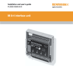
The MI 5 is fully described in
User's guide H-2000-5014
The MI 5 interface is used with inductive and/or hard
wired signal transmission systems. System status is
presented visually in a continuously updated form,
on the front panel diagnostic LED display, and by outputs
available from the MI 5 to the CNC control.
Front view
APPENDIX 2
MI 8 INTERFACE UNIT
The MI 8 is fully described in
User's guide H-2000-5015
The MI 8 interface is used with hard wired signal
transmission systems. System status is presented
visually in a continuously updated form on the front
panel diagnostic LED display, and by outputs available
from the MI 8 to the CNC control.
Front view
Probe status LED
Lit when probe is at rest
or interface is inhibited.
LED off indicates probe
stylus is deflected or power
is off.
Audible Indicator
A tone is emitted
each time stylus is
defected or returns
to rest.
INTERFACE UNIT
Interface units convert probe signals
into an acceptable form for the CNC
machine control.
Probe status LED
Lit when probe is at rest
or interface is inhibited.
Switch SW1
Output N/C
(Normally closed)
LED off indicates probe
stylus is deflected or power
is off.
Output N/O
(Normally open)
APPENDIX 4
PSU3 POWER SUPPLY UNIT
The PSU3 is fully described in
User's guide H-2000-5057
APPENDIX 3
MI 8-4 INTERFACE UNIT
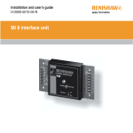
The MI 8-4 is fully described in
User's guide H-2000-5008
The MI 8-4 is used with hard wired signal transmission
systems. it connects to the machine control input, or it
connects into the 4 wire Fanuc 'Automatic Length
Measurement' input (XAE, ZAE).
Front view
The PSU3 provides a +24 V supply for Renishaw
interface units when a power supply is not
available from the CNC machine control.
Front view
Power LED
When the green LED is lit,
the power supply is on.
Rear view
Bi-colour Probe Status LED
Green when probe is at rest or
interface is inhibited.
Red when probe stylus is
deflected.
LED off indicates power is off.
Switch SW1
Output high
or
output low
Diagnostic LEDs
Indicate direction of
machine movement
Mains switch
On/off
1-18
PARTS LIST Please quote the Part no. when ordering equipment
Type
Part no.
MP4-S
A-2054-3968
Description
MP4-S probe (side exit) with conduit adaptor,
and cable 4.8 m (15ft 9 in) long and tool kit.
MP4-R
A-2054-6373
MP4-R probe (rear exit) with cable 4.8 m (15ft 9 in) long and tool kit.
PSI-14
A-5000-6701
Cube stylus 43 mm (1.69 in) long.
DK1
A-2051-7105
Probe outer diaphragm replacement kit.
Tool kit
A-2054-6496
Probe head tool kit comprising :
Stylus tool Ø1.98 and hexagon keys 1.5 mm AF,
2.0 mm AF, 2.5 mm AF, 3.0 mm AF, 4.0 mm AF, 6.0 mm AF,
and modified (shortened) hexagon key 3.0 mm AF.
1-19
Renishaw plc
New Mills, Wotton-under-Edge,
Gloucestershire, GL12 8JR
United Kingdom
T +44 (0)1453 524524
F +44 (0)1453 524901
E [email protected]
www.renishaw.com
For worldwide contact details,
please visit our main website at
www.renishaw.com/contact
*H-2000-5004-01-H*