1
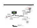
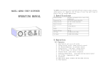
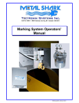
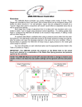
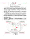
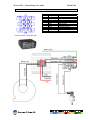
70 Series EPC - Manual Pump User Guide
98-05073 R1
1. Connections table and Assembly
Contact
1
2
3
4
5
6
7
8
9
10
11
12
View from cable (45-05424) side
Color
Description
Green
Boom Sense input (+12v = work)
Red
White
Regulation output +12v
Pressure Signal
Black
+12v Pressure Sensor
Black
Regulation output -GND
2. System overview
2864 Old Rochester Road
Springfield, IL 62703
Phone (217) 753-8424 – Fax (217) 753-8426
www.mid-tech.com
70 Series EPC - Manual Pump User Guide
98-05073 R1
3. Generality
Function
Key
Description
The unit will power on and show the first working screen
1. Power on
Pro
US Units
↑ and ↓
2. Power off
3. Selection of
working screen
↑ or ↓
4. Master
Pump ON/OFF
Pro ON/OFF
0 psi
0.0 Ga
Metric Units
0 Bar
0.0 lt
The unit will power off
The first line on display show dose rate
Second line is user selectable
If Boom Sense in NOT used Pro can be used to turn
the pump ON/OFF
4. Functionality
Function
1. Pressure
Flow
When
Master is
ON
2. Pressure
Flow
When
Master is
OFF
Display
15 psi
35.0 gpm
1 bar
35.0 l/m
Possible actions
↑ to increase pump (pressure)
RPM
↓ to decrease pump (pressure)
RPM
15 psi
0.0 ga
1 psi
0.0 lt
Comments
Upper line : Actual pressure
Lower line : Actual Flow rate
Upper line : Actual pressure
CLR for 3 second to reset
second line.
Lower line : Accumulated
volume or Total Volume
5. Alarms
Function
1. No
Pressure
Signal
2. No
Pressure
in system
Display
Error
pressure
Possible actions
CLR to disable alarm
Alarm message will appear on
the second line indicating that
no pressure signal is received;
Check pressure sensor for
damaged or bad connection.
CLR to disable alarm
Alarm message will appear on
the second line indicating that
there is no pressure in the
system. Tank could be empty or
pump could be stopped.
0 psi
no press
0 Bar
no press
Comments
6. Program
Function
Display
Access
Possible actions
Push Pro for 3 seconds
Exit
Push Pro for 3 seconds
Comments
Master must be off
↓ to select another step
1. Nozzle
nozzle
setup
Iso 04
0.40 g/m
1.1
Iso 04
1.31 l/m
@ 40 psi
1.43 g/m
1.2
2. Pressure
sensor
@ 2 bar
1.12 l/m
pressure
setup
Pro to enter nozzle setup (1.1)
Push Pro for 3 seconds to escape
program
↑ ↓ to select a nozzle
Pro to validate selected nozzle
If a programmable nozzle is needed
select programmable nozzle and
push Pro go to step 1.2:
programmable nozzle value.
↑ ↓ to modify gal/min value
Pro to validate value
US Units
Enter nozzle rating in gallons
/ minute @ 40PSI
Metric Units
Enter nozzle rating in liters /
minute @ 2Bar
↑ ↓ to select another step
Pro to enter calibration (2.1)
Maximum pressure allowed
by the sensor.
Push Pro for 3 seconds to escape
program
Max prs
150 psi
2.1
2.2
2.3
Max prs
10 bar
Calibr.
At 0 psi
Calibr.
At 0 bar
Delta pr
5
↑ ↓ to modify max pressure value
Pro to validate max pressure and go
to the zero PSI calibration (2.2)
Max pressure rating for the
sensor can be found on the
sensor or by contacting your
70 series monitor distributor.
Pro for auto calibration of the
pressure sensor at zero PSI
!!! Be sure there is no
pressure in the
system !!!
↑ ↓ to modify value
Pro to validate value
2864 Old Rochester Road
Springfield, IL 62703
Phone (217) 753-8424 – Fax (217) 753-8426
www.mid-tech.com
This value is used to compensate
the pressure drop between pressure
measurement point and nozzle.
If not needed, set it to 0.The higher
the value, the higher the
compensation.