1
Lingg & Janke
eibDUO
Multipurpose Switching Actuator
with Power Supply Unit and Interface
Configuration
The factory settings of the actuator do not feature
any device or group addresses. The functions
required are assigned when setting the parameters.
During the planning phase with ETS, objects which
are not assigned are not displayed either.
L1
L2
L3
N
PE
NTA6F16H+COM
NTA6F16H+USB
X X X X X X
Description
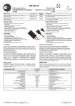
The eibDUO switching actuator with power supply
unit consits of a 6-fold actuator, a 640/320mA power
supply unit and a USB/RS232 interface in one
casing. It is especially suited for high loads, also
capacitive loads, with high start-up peaks (C load).
The operability of the USB interface is only
given with ETS 3/4!
reset-switch
activate > 20s
The application programm must always be fully
downloaded to the device, never partially. Partial
download of the programm may lead to
malfunctions.
The load for each channel is 16A at 250V AC, each
channel can be assigned its own mains phase. Each
channel is connected to a screwless twin terminal,
which allows the phase to be looped through in
compliance with existing regulations and two loads
to be connected to the terminal. Each channel can
be operated manually by a relay mover which also
indicates the status of the switch.
A
A`
B
B`
C
C`
D
D`
E
E`
F
F`
Reset
On
I > Imax
Technical Data of Actuator
Installation
The device is mounted on a DIN rail, DIN EN 60715
TH35
max. group addresses
40
power supply
24V DC via EIB/KNX
auxiliary power supply
not necessary
protection class
IP 20
dimensions
216 x 90 x 65 mm (12 RU*)
installation
35 mm DIN rail
mechanical life-cycle
10^6 switching operations
operating temperature
-5 ... +45°C
- the upper and lower tiers of terminals A
to F' are each individually wired
The device must only be installed and
configured by a qualified professional!
rated load per contact
16A /250V AC 50...60Hz
- terminal cross section: 0.08 - 2.5 mm²
If the outlets are connected to different
mains phases which are not protected by
the same protector unit, a clearly visible
note to that effect has to be attached to the
device!
maximum power load per contact
incandescent lamp load
flourescent lamp load
low-voltage halogen
3680W
compensated 3680W
uncomp. (Cmax. 200uF) 2500W
with transformator 2000W
*RU = rail unit
important:
programming with ETS 3.0b
- product data base 05/2006 or later
- current service patch installed
LED USB interface
datatransfer / EIB
LED USB interface
standard operation
LED and programming button
for 6-fold actuator
EIB/KNX
_
+
Position the device on the DIN rail from above.
Apply brief, strong pressure on the lower edge of
the casing to engage the casing with the rail.
( LED and programming button for RS232 interface )
Terminals
- stripping lenght: 5 - 6 mm
- conductors permitted:
- single core
- multi-filar
- fine-wired, including tin-plated
individual wires
- fine-wired, with wire end sleeves
The total load must not cause overheating of the device!
Warnings
The device can be removed from the rail without
any tools: simply slide it from the DIN rail upwards
and remove it from the top of the rail. Do not apply
any force lest the clamps be damaged.
To connect the wires to the screwless terminals,
insert a slotted screwdriver into the respective
mounting hole under the terminal, which opens the
terminal. Insert the wire into the mounting hole and
remove the screwdriver. The wire is now locked in
place.
Health and safety regulations have to be
compiled with!
Do not open the device!
A faulty device must be returned
immediately to Lingg & Janke OHG!
Lingg & Janke OHG
Zeppelinstraße 30
78315 RADOLFZELL
GERMANY
technical support:
tel. (+49) 7732 - 94557-71
www.lingg-janke.de