1
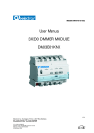
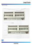
ABB i-bus® EIB
Busch-Watchdog presence detector
Type: 6131-74-101
The Busch-Watchdog® presence
detector is mounted on a bus coupler
FM, switch actuator/sensor FM or a
switch/dim actuator FM.
In addition to the detection of
movement, the sensor can record
movement that occurs within a certain
time period with the help of its
integrated signal function. It is thus
possible to integrate the sensor in
detector systems.
The presence detector is used for
switching operations and/or constant
lighting control of lighting systems and/
or HVAC systems.
The recovery time and the sensitivity of
the built-in twilight switch can be set
using the three potentiometers on the
rear of the presence detector or via the
parameters in ETS.
The sensor can switch a heating,
ventilation or air conditioning system
on or off independent of the lighting
controller. Constant lighting control can
be implemented via additional objects.
The detection area can be adapted to
the ambient conditions using the film
supplied.
Technical data
Power supply
Operating and display elements
Connections
Type of protection
Ambient temperature range
Mounting
Dimensions
Weight
Certification
CE norm
–
–
–
–
–
–
–
–
EIB
3 potentiometers
Potentiometer “Lux1”
Potentiometer “Time Illumination”
Potentiometer “Time HVAC”
Bus coupler FM or
Switch actuator/sensor FM
IP 20, EN 60 529
mounted on the bus coupler
– Operation
– Storage
– Transport
– latched onto flush-mounted insert
– 110 x 51 mm (Ø x H)
– 0.1 kg
– EIB-certified
– in accordance with the EMC gudeline
and the low voltage guideline
24 V DC, via the bus line
Twilight sensor 5 … 1000 lux
Recovery time 10 s … 32 min
Recovery time 1 min … 60 min
10-pole plug connector
- 5 °C … 45 °C
-25 °C … 55 °C
-25 °C … 70 °C
Standard detection area
2,5 m
1,0 m
6,0 m
2 - 68
May 2002
ABB i-bus® EIB
Busch-Watchdog presence detector
Type: 6131-74-101
Application programs
Number of
communication objects
Max. number of
group addresses
Max. number of
associations
For bus coupler FM:
Switch Value Cyclic Monitoring /1
Switch Value Cyclic HVAC /1
Switch Value Cyclic HVAC Monitoring /1
Switch Dim Cyclic HVAC Monitoring Bright. control /1
11
11
11
12
29
29
29
29
29
29
29
28
For switch actuator/sensor FM:
Switch Value Cyclic Monitoring /2
Switch Value Cyclic HVAC /2
Switch Value Cyclic HVAC Monitoring /2
11
11
11
29
29
29
29
29
29
For switch/dim actuator FM:
Schalten Dim Cyclic HVAC Monitoring Bright. control /1
12
29
28
Circuit diagrams
+
EIB -
+
EIB -
1
1
2
2
4
3
L
N
7
8
7
2
6
1
5
1 Bus cable
2 Bus terminal
3 Bus coupler FM
4 Switch actuator FM
Note
The Busch-Watchdog® presence
detector is solely intended for indoor
use e.g. in schools, offices or
residential buildings.
The full functionality of the device is
dependent on the mounting height.
The area of detection can additionally
be adapted via a film that is supplied
with the device.
May 2002
5 Switch/dim actuator FM
6 Electronic ballast with 0 (1) - 10 V
control input
7 Supply terminals
8 230 V mains voltage
Application examples and detailed
information e.g. about “intelligent”
HVAC system control and settings for
the potentiometers can be found in the
user manual “Busch-Watchdog
presence detector”.
2 - 69
ABB i-bus® EIB
Busch-Watchdog presence detector
Type: 6131-74-101
Switch Value Cyclic Monitoring /1
Using the application, the presence
detector can sense movement in its
field of detection and send switching or
value telegrams.
1
lx, PIR
Selection in ETS2
– ABB
Phys. Sensors
Presence detector
The application makes two
independent channels available which
can be used to switch on the lighting. It
also has a monitoring function.
When assigning parameters, it should
be noted that some parameters (if
required) are only visible in the “High
Access” setting and can only then be
modified.
Switch
The presence detector sends
switching telegrams to its
communication objects “Movement
channel ... / Telegr. switch” as soon as it
records movement in its detection
area. The value of the switching
telegram can be set with the parameter
“Sending at detection”. It is possible to
send an “ON telegram”, an “OFF
telegram” or “no telegram” on
detection of movement. The “On” or
“Off” telegrams can also be sent
cyclically.
If the presence detector no longer
detects any movement once the
recovery time has elapsed, it is
possible to send an “ON telegram”, an
“OFF telegram” or “no telegram”. The
“On” or “Off” telegrams can also be
sent cyclically. The behaviour is
specified with the parameter “Telegram
after recovery time”.
Each channel of the presence detector
can be enabled/disabled separately.
The communication objects
“Movement channel ... / Activation” are
used for this purpose. The objects can
be made visible with the parameter.
Example:
In a functional building, all the
presence detectors should be enabled
at a specific time in the morning. A “1”
is therefore sent to a central location
with a time switch and then received at
the communication objects “Movement
channel ... / Activation”. In this example,
the parameter “Activation object
movement” is set to “ON telegram”.
Value
Value telegrams can also be sent on
detection of movement. To do so, the
parameter “Type of movement object”
must be changed from “Switching
(EIS 1)” to “Value (EIS 6)”. Dimming
actuators can thus be dimmed to a
value that is lower than the maximum
value e.g. in order to dim on with base
lighting.
The value that is sent is defined with
the parameters “Sending at the
beginning/end of detection”. It is also
possible to select that no telegrams
are sent.
Cyclic
All switching telegrams can also be
sent cyclically. It should be ensured
that the respective parameter setting
“ON telegram cyclically” or “OFF
telegram cyclically” is selected.
The total cyclic time can be set using
the parameters “Time base for cyclical
sending” and “Time factor for cyclical
sending”.
The period in which a telegram is
repeated cyclically is composed of a
base and a factor:
Cyclic time= Base * Factor
If the presence detector receives a
telegram at this object, the presence
detector is activated or deactivated.
With the parameters “At .... the
movement”, it is possible to select
whether a telegram is sent once at
movement or once after detection of
movement or no telegrams are sent via
the communication object “Movement
channel ... / Telegr. switch”.
2 - 70
May 2002
ABB i-bus® EIB
Busch-Watchdog presence detector
Type: 6131-74-101
Channel adjustments
Light source
The setting of the threshold for the light
sensor as well as the recovery time
can be carried out using the
potentiometer at the back of the
presence detector. There is a separate
setting aid for this purpose. The
illumination threshold is defined for
channel 1 with the “Lux1
potentiometer”. The “HVAC
potentiometer” presets the illumination
threshold for channel 2. The
“Illumination potentiometer” sets the
recovery time for both channels.
With an increasing proportion of
external light, the presence detector
sends an “Off” telegram as soon as the
external light has reached the required
illuminance. The type of light source
must be indicated for this purpose.
Alternatively, the settings can be
carried out in ETS. To do so, the
adjustment parameters should be
changed from “... potentiometer” to
“ETS”.
With the parameter “Threshold
illumination adjustable with”, the
brightness value that triggers the
presence detector can be indicated.
Values between 5 lux and 1000 lux
can be entered. The recovery time can
be set with the two parameters “Time
base of recovery time” and “Time factor
of recovery time”. The recovery time is
produced from the base and the factor:
Recovery time = Base * Factor
Brightness-dependent switching
A further communication object can
also be enabled separately for each
channel with the parameter “Activation
object brightness dependent
switching”. If the communication object
“Brightness dependent switching
channel ...” receives a “1”, the
presence detector switches on without
dependence on brightness. The
threshold settings that have been
carried out with the potentiometer at
the rear of the device or with ETS, do
not have any significance for the
duration of the activation. If a “0” is
received at the object, the presence
detector only sends “On” telegrams
again once the brightness value has
fallen below the illumination threshold.
May 2002
Example:
Illuminance 500 lux
The illumination threshold of 500 lux is
preset via the potentiometer on the
presence detector or via the ETS
program.
If movement is now detected in a dark
room in the morning and the
brightness value lies below 500 lux,
the presence detector sends an “On”
telegram when it records movement.
a) switched light source:
When the luminaires are switched on,
they generate a luminance of 500 lux.
The external light coming in is added
to this. The presence detector switches
off if it measures a luminance level of
1000 lux.
b) controlled light source (constant
brightness):
If a conventional constant brightness
controller is built into the luminaires,
this regulates the proportion of artificial
light so that the measured luminance
stays constant at 500 lux. If the
presence detector now records a
measurement of more than 500 lux,
the luminaires have already been
dimmed down to the minimum
brightness value and are switched off.
Monitoring
It is possible to activate a monitoring
function. To do so, the general
parameter ”Monitoring function” must
be set to “yes”. The monitoring function
represents a “quasi alarm signal”
which is not triggered when the
smallest thermal movement is detected
but when a strong energy source is
registered by the presence detector in
a short space of time or several weak
sources are detected during a longer
period.
2 - 71
ABB i-bus® EIB
Busch-Watchdog presence detector
Type: 6131-74-101
If the monitoring function is activated, a
further communication object is
available “Signal / Telegr. ...”. The
presence detector records the intensity
and number of movements within a
time period and only sends telegrams
when a set sensitivity level has been
exceeded.
If the monitoring function should be
enabled externally, this can be carried
out with the communication object
“Signal / Activation”. To do so, the
parameter “Activation object
monitoring” must previously be set to
“available”.
Bus voltage recovery
On a further parameter page
“Monitoring function”, it is possible to
set the type of the monitoring object
(1 bit or 1 byte), the type of telegram at
both the start and end of detection as
well as the cyclical sending behaviour.
The parameter “Threshold” indicates
the sensitivity range. The value “0”
denotes maximum sensitivity while the
value “255” means minimum
sensitivity.
It can also be parameterised when the
presence detector switches to the
monitoring function once it has been
activated. This period is again
composed of a time base and factor in
the same way as the cyclic time.
2 - 72
The states of the communication
objects “Movement channel ... / Telegr.
switch” adopt a defined status on bus
voltage recovery. The states of
channels 1 and 2 can be defined
separately. There are thus no
unnecessary switching operations on
bus voltage recovery.
Defined states can also be selected for
the objects “Brightness dependent
switching channel ...”. The parameters
are only visible if the objects have
previously been enabled.
May 2002
ABB i-bus® EIB
Busch-Watchdog presence detector
Type: 6131-74-101
Communication objects
No.
0
1
3
4
Type
1 bit
1 bit
1 bit
1 bit
Object name
Movement channel
Movement channel
Movement channel
Movement channel
1
1
2
2
Function
Telegr. switch
Activation
Telegr. switch
Activation
Communication objects
with sending of value telegram
No.
0
1
3
4
Type
1 byte
1 bit
1 byte
1 bit
Object name
Movement channel
Movement channel
Movement channel
Movement channel
1
1
2
2
Function
Telegr. value
Activation
Telegr. value
Activation
Communication objects
with monitoring objects
No.
…
6
7
Type
Object name
Function
1 bit
1 bit
Signal
Signal
Telegr. switch
Activation
No.
…
6
7
Type
Object name
Function
1 byte
1 bit
Signal
Signal
Telegr. value
Activation
No.
…
2
Type
Object name
Function
1 bit
Brightness dependent
switching channel 1
Activation
1 bit
Brightness dependent
switching channel 2
Activation
Communication objects
with value monitoring objects
Communication objects
with brightness-dependent switching
…
5
…
May 2002
2 - 73
ABB i-bus® EIB
Busch-Watchdog presence detector
Type: 6131-74-101
Parameters for “Low Access”
The default setting for the values
is printed in bold type.
Parameters for presence detector with “Low Access”:
General:
– Monitoring function
yes
no
Only if “yes” is selected:
Monitoring function:
– Activation object monitoring
not available
available
Only if available:
– enable monitoring function at
ON telegram
OFF telegram
– Type of monitoring object
Switching (EIS 1)
Value (EIS 6)
Only for “Switching (EIS 1)”:
– Sending at the beginning of
ON telegram
detection
OFF telegram
ON telegram cyclically
OFF telegram cyclically
no telegram
– Sending at the end of detection
ON telegram
OFF telegram
ON telegram cyclically
OFF telegram cyclically
no telegram
– Time base for cyclical sending
130 ms / 2.1 s / 34 s / 9 min
– Time factor for cyclical sending
100
Only for “Value (EIS 6)”:
– Sending at the beginning of
100 % / 90 % / … / 20 % / 10 % / OFF /
detection
no telegram
– Sending at the end of detection
100 % / 90 % / … / 20 % / 10 % / OFF /
no telegram
– No alarm sends
0
– Threshold
4
(1: sensitive / 255: insensitive)
– Time base till watchdog is in
0.5 ms / 8.2 ms / 130 ms / 2.1 s / 34 s /
monitoring function
9 min
– Time factor till watchdog is in
100
monitoring function
– Behaviour on bus voltage recovery
(communication objects)
Only if brightness object is enabled:
– Brightness dependent switching
disabled
(Illmination channel 1)
enabled
– Brightness dependent switching
disabled
(Illumination channel 2)
enabled
– Movement
disabled
(Illumination channel 1)
enabled
– Movement
disabled
(Illumination channel 2)
enabled
Separate for illumination channels 1 and 2:
– Activation object movement
not available
available
Only if activation object for movement
is available:
– enabling movement at
ON telegram
OFF telegram
– Type of movement object
Switching (EIS 1)
– Sending at detection
ON telegram
OFF telegram
ON telegram cyclically
OFF telegram cyclically
no telegram
2 - 74
May 2002
ABB i-bus® EIB
Busch-Watchdog presence detector
Type: 6131-74-101
Parameters for “Low Access”
The default setting for the values
is printed in bold type.
– Telegram after recovery time
– Time base for cyclical sending
– Time factor for cyclical sending
Parameters for “High Access”
The default setting for the values
is printed in bold type.
Additional parameters for “High Access”:
Separate for illumination channel 1 and 2:
– Activation object brightness dependent not available
switching
available
Only if object is available:
– at disabling the movement
do not send a telegram
send telegram at movement once
send telegr. once after detection
– at enabling the movement
do not send a telegram
send telegram at movement once
send telegr. once after detection
– Type of movement object
Switching (EIS 1)
Value (EIS 6)
Only for “Value (EIS 6)”:
– Sending at detection
100% / 90 % / … / 10 % / OFF /
no telegram
– Telegram after recovery time
100% / 90 % / … / 10 % / OFF /
no telegram
Adjustments channel 1:
– Threshold illumination adjustable
with
Only if “ETS” is selected:
– Threshold illumination
(5 lux …1000 lux)
– Recovery time adjustable with
Only if “ETS” is selected:
– Potentiometer should not be at TEST
– Time base of recovery time
– Time factor of recovery time
– Light source
Adjustments channel 2:
– Threshold illumination adjustable
with
Only if “ETS” is selected:
– Threshold illumination
(5 Lux …1000 lux)
– Recovery time adjustable with
Only if “ETS” is selected:
– Potentiometer should not be at TEST
– Time base of recovery time
– Time factor of recovery time
– Light source
May 2002
ON telegram
OFF telegram
ON telegram cyclically
OFF telegram cyclically
no telegram
130 ms / 2.1 s / 34 s / 9 min
10
ETS
Lux1 potentiometer
100
ETS
Illumination potentiometer
0.5 ms / 8.2 ms / 130 ms / 2.1 s /
34 s / 9 min
100
switched
controlled (constant brightness)
ETS
HVAC potentiometer
100
ETS
Illumination potentiometer
0.5 ms / 8.2 ms / 130 ms / 2.1 s /
34 s / 9 min
100
switched
controlled (constant brightness)
2 - 75
ABB i-bus® EIB
Busch-Watchdog presence detector
Type: 6131-74-101
Switch Value Cyclic HVAC /1
Using the application, the presence
detector can sense movement in its
field of detection and send switching or
value telegrams.
1
lx, PIR
Selection in ETS2
– ABB
Phys. Sensors
Presence detector
The application makes two
independent channels available which
can be used to switch on the lighting
and one channel to influence the
HVAC controller.
When assigning parameters, it should
be noted that some parameters (if
required) are only visible in the “High
Access” setting and can only then be
modified.
Switch
The presence detector sends
switching telegrams to its
communication objects “Movement
channel ... / Telegr. switch” as soon as it
records movement in its detection
area. The value of the switching
telegram can be set with the parameter
“Sending at detection”. It is possible to
send an “ON telegram”, an “OFF
telegram” or “no telegram” on
detection of movement. The “On” or
“Off” telegrams can also be sent
cyclically.
If the presence detector no longer
detects any movement once the
recovery time has elapsed, it is
possible to send an “ON telegram”, an
“OFF telegram” or “no telegram”. The
“On” or “Off” telegrams can also be
sent cyclically. The behaviour is
specified with the parameter “Telegram
after recovery time”.
Each channel of the presence detector
can be enabled/disabled separately.
The communication objects
“Movement channel ... / Activation” are
used for this purpose. The objects can
be made visible with the parameter.
Example:
In a functional building, all the
presence detectors should be enabled
at a specific time in the morning. A “1”
is therefore sent to a central location
with a time switch and then received at
the communication objects “Movement
channel ... / Activation”. In this example,
the parameter “Activation object
movement” is set to “ON telegram”.
Value
Value telegrams can also be sent on
detection of movement. To do so, the
parameter “Type of movement object”
must be changed from “Switching
(EIS 1)” to “Value (EIS 6)”. Dimming
actuators can thus be dimmed to a
value that is lower than the maximum
value e.g. in order to dim on with base
lighting.
The value that is sent is defined with
the parameters “Sending at the
beginning/end of detection”. It is also
possible to select that no telegrams
are sent.
Cyclic
All switching telegrams can also be
sent cyclically. It should be ensured
that the respective parameter setting
“ON telegram cyclically” or “OFF
telegram cyclically” is selected.
The total cyclic time can be set using
the parameters “Time base for cyclical
sending” and “Time factor for cyclical
sending”.
The period in which a telegram is
repeated cyclically is composed of a
base and a factor:
Cyclic time= Base * Factor
If the presence detector receives a
telegram at this object, the presence
detector is activated or deactivated.
With the parameters “At .... the
movement”, it is possible to select
whether a telegram is sent once at
movement or once after detection of
movement or no telegrams are sent via
the communication object “Movement
channel ... / Telegr. switch”.
2 - 76
May 2002
ABB i-bus® EIB
Busch-Watchdog presence detector
Type: 6131-74-101
Channel adjustments
Light source
The setting of the threshold for the light
sensor as well as the recovery time
can be carried out using the
potentiometer at the back of the
presence detector. There is a separate
setting aid for this purpose. The
illumination threshold is defined for
channel 1 with the “Lux1
potentiometer”. The “HVAC
potentiometer” presets the illumination
threshold for channel 2. The
“Illumination potentiometer” sets the
recovery time for both channels.
With an increasing proportion of
external light, the presence detector
sends an “Off” telegram as soon as the
external light has reached the required
illuminance. The type of light source
must be indicated for this purpose.
Alternatively, the settings can be
carried out in ETS. To do so, the
adjustment parameters should be
changed from “... potentiometer” to
“ETS”.
With the parameter “Threshold
illumination adjustable with”, the
brightness value that triggers the
presence detector can be indicated.
Values between 5 lux and 1000 lux
can be entered. The recovery time can
be set with the two parameters “Time
base of recovery time” and “Time factor
of recovery time”. The recovery time is
produced from the base and the factor:
Recovery time = Base * Factor.
Brightness-dependent switching
A further communication object can
also be enabled separately for each
channel with the parameter “Activation
object brightness dependent
switching”. If the communication object
“Brightness dependent switching
channel ...” receives a “1”, the
presence detector switches on without
dependence on brightness. The
threshold settings that have been
carried out with the potentiometer at
the rear of the device or with ETS, do
not have any significance for the
duration of the activation. If a “0” is
received at the object, the presence
detector only sends “On” telegrams
again once the brightness value has
fallen below the illumination threshold.
May 2002
Example:
Illuminance 500 lux
The illumination threshold of 500 lux is
preset via the potentiometer on the
presence detector or via the ETS
program.
If movement is now detected in a dark
room in the morning and the
brightness value lies below 500 lux,
the presence detector sends an “On”
telegram when it records movement.
a) switched light source:
When the luminaires are switched on,
they generate a luminance of 500 lux.
The external light coming in is added
to this. The presence detector switches
off if it measures a luminance level of
1000 lux.
b) controlled light source (constant
brightness):
If a conventional constant brightness
controller is built into the luminaires,
this regulates the proportion of artificial
light so that the measured luminance
stays constant at 500 lux. If the
presence detector now records a
measurement of more than 500 lux,
the luminaires have already been
dimmed down to the minimum
brightness value and are switched off.
2 - 77
ABB i-bus® EIB
Busch-Watchdog presence detector
Type: 6131-74-101
HVAC
The presence detector can activate a
heating or ventilation controller with its
object “Movement HVAC”. The object
sends telegrams without dependence
on the brightness value.
The ON delay is the period which the
HVAC channel needs until it detects a
movement. This period is automatically
set by default by the presence detector.
It can however also be preselected. To
do so, the parameter “Switch ON is
adjustable” must be set to “by ETS”.
The time is composed of a base and a
factor in the same way as the recovery
time.
If the switch ON behaviour is set with
the HVAC potentiometer, the following
should be noted:
– If an OFF delay between 1 and 10
min is assigned with the
potentiometer, the ON delay is set at
30 s. This setting can for example
switch on an extractor fan in the WC.
– If the OFF delay is set at longer than
10 min, the ON time is based on the
frequency of detection of movement.
In a standard office, the heating
system is only switched on when the
employee stays there for a longer
period. In a conference room which
is seldom used, the heating is not
activated when someone enters the
room briefly and then leaves again
after a short period.
2 - 78
The object “Movement HVAC” can
trigger a telegram after detection of a
movement and after an adjustable
recovery time. With the parameter
“Type of movement object”, it is
possible to set whether 1 bit switching
telegrams or 1 byte value telegrams
are triggered. The switching telegrams
can also be sent cyclically in the same
way as the movement channels.
Bus voltage recovery
The states of the communication
objects “Movement channel ... / Telegr.
switch” adopt a defined status on bus
voltage recovery. The states of
channels 1 and 2 can be defined
separately. There are thus no
unnecessary switching operations on
bus voltage recovery.
Defined states can also be selected for
the objects “Brightness dependent
switching channel ...”. The parameters
are only visible if the objects have
previously been enabled.
May 2002
ABB i-bus® EIB
Busch-Watchdog presence detector
Type: 6131-74-101
Communication objects
No.
0
1
3
4
6
7
Type
1 bit
1 bit
1 bit
1 bit
1 bit
1 bit
Object name
Movement channel
Movement channel
Movement channel
Movement channel
Movement HVAC
Movement HVAC
Communication objects
with sending of value telegrams
No.
0
1
3
4
6
7
Type
1 byte
1 bit
1 byte
1 bit
1 byte
1 bit
Object name
Movement channel
Movement channel
Movement channel
Movement channel
Movement HVAC
Movement HVAC
Communication objects
with brightness-dependent switching
No.
…
2
Type
Object name
Function
1 bit
Brightness dependent
switching channel 1
Activation
1 bit
Brightness dependent
switching channel 2
Activation
…
5
1
1
2
2
1
1
2
2
Function
Telegr. switch
Activation
Telegr. switch
Activation
Telegr. switch
Activation
Function
Telegr. value
Activation
Telegr. value
Activation
Telegr. value
Activation
…
May 2002
2 - 79
ABB i-bus® EIB
Busch-Watchdog presence detector
Type: 6131-74-101
Parameters for “Low Access”
The default setting for the values
is printed in bold type.
Parameters for presence detector with “Low Access”:
General:
– Behaviour on bus voltage recovery
(communication objects)
Only if brightness object is enabled:
– Brightness dependent switching
disabled
(Illumination channel 1)
enabled
– Brightness dependent switching
disabled
(Illumination channel 2)
enabled
– Movement
disabled
(Illumination channel 1)
enabled
– Movement
disabled
(Illumination channel 2)
enabled
– Movement
disabled
(HVAC)
enabled
Separate for illumination channels 1 and 2:
– Activation object movement
not available
available
Only if object is available:
– enabling movement at
ON telegram
OFF telegram
– Type of movement object
Switching (EIS 1)
– Sending at detection
ON telegram
OFF telegram
ON telegram cyclically
OFF telegram cyclically
no telegram
– Telegram after recovery time
ON telegram
OFF telegram
ON telegram cyclically
OFF telegram cyclically
no telegram
– Time base for cyclical sending
130 ms / 2.1 s / 34 s / 9 min
– Time factor for cyclical sending
10
HVAC:
– Activation object movement
Only if object is available:
– enabling movement at
– Type of movement object
– Sending at detection
– Telegram after recovery time
– Time base for cyclical sending
– Time factor for cyclical sending
2 - 80
not available
available
ON telegram
OFF telegram
Switching (EIS 1)
ON telegram
OFF telegram
ON telegram cyclically
OFF telegram cyclically
no telegram
ON telegram
OFF telegram
ON telegram cyclically
OFF telegram cyclically
no telegram
130 ms / 2.1 s / 34 s / 9 min
10
May 2002
ABB i-bus® EIB
Busch-Watchdog presence detector
Type: 6131-74-101
Parameters for ‘High Access”
The default setting for the values
is printed in bold type.
Additional parameters for “High Access”:
Separately for illumination channels 1 and 2:
– Activation object brightness
not available
dependent switching
available
Only if activation object movement is available:
– at disabling the movement
do not send a telegram
send telegram at movement once
send telegr. once after detection
– at enabling the movement
do not send a telegram
send telegram at movement once
send telegr. once after detection
– Type of movement object
Switching (EIS 1)
Value (EIS 6)
Only if “Value (EIS 6)” is selected:
– Sending at detection
100% / 90 % / … / 10 % / OFF /
no telegram
– Telegram after recovery time
100% / 90 % / … / 10 % / OFF /
no telegram
Adjustments channel 1:
– Threshold illumination adjustable
ETS
with
Lux1 potentiometer
Only if “ETS” is selected:
– Threshold illumination
100
(5 lux … 1000 lux)
– Recovery time adjustable with
ETS
Illumination potentiometer
Only if “ETS” is selected:
– Potentiometer should not be at TEST
– Time base of recovery time
0.5 ms / 8.2 ms / 130 ms / 2.1 s /
34 s / 9 min
– Time factor of recovery time
100
– Light source
switched
controlled (constant brightness)
Adjustments channel 2:
– Threshold illumination adjustable
ETS
with
HVAC potentiometer
Only if “ETS” is selected:
– Threshold illumination
100
(5 lux … 1000 lux)
– Recovery time adjustable with
ETS
Illumination potentiometer
Only if “ETS” is selected:
– Potentiometer should not be at TEST
– Time base of recovery time
0.5 ms / 8.2 ms / 130 ms / 2.1 s /
34 s / 9 min
– Time factor of recovery time
100
– Light source
switched
controlled (constant brightness)
May 2002
2 - 81
ABB i-bus® EIB
Busch-Watchdog presence detector
Type: 6131-74-101
Parameters for “High Access”
The default settings for the values
is printed in bold type.
HVAC:
– at disabling the movement
– at enabling the movement
– Type of movement object
Only if “Value (EIS 6)“ is selected:
– Sending at detection
Adjustments HVAC:
– Recovery time adjustable with
Only if “ETS” is selected:
– Potentiometer should not be at TEST
– Time base of recovery time
– Time factor of recovery time
– Switch ON is adjustable
Only if “ETS” is selected:
– Time base of switch ON delay
– Time factor of switch ON delay
2 - 82
do not send a telegram
send telegram at movement once
send telegr. once after detection
do not send a telegram
send telegram at movement once
send telegr. once after detection
Switching (EIS 1)
Value (EIS 6)
100% / 90 % / … / 10 % / OFF /
no telegram
HVAC potentiometer
ETS
0.5 ms / 8.2 ms / 130 ms / 2.1 s /
34 s / 9 min
100
automatically
by ETS
0.5 ms / 8.2 ms / 130 ms / 2.1 s /
34 s / 9 min
100
May 2002
ABB i-bus® EIB
Busch-Watchdog presence detector
Type: 6131-74-101
Switch Value Cyclic HVAC
Monitoring /1
Using the application, the presence
detector can sense movement in its
field of detection and send switching or
value telegrams.
1
lx, PIR
Selection in ETS2
– ABB
Phys. Sensors
Presence detector
The application makes two
independent channels available. One
can be used to switch on the lighting
while the other channel can switch on
an HVAC system. The presence
detector also has a monitoring
function.
When assigning parameters, it should
be noted that some parameters (if
required) are only visible in the “High
Access” setting and can only then be
modified.
Switch
The presence detector sends
switching telegrams to its
communication objects “Movement
channel ... / Telegr. switch” as soon as it
records movement in its detection
area. The value of the switching
telegram can be set with the parameter
“Sending at detection”. It is possible to
send an “ON telegram”, an “OFF
telegram” or “no telegram” on
detection of movement. The “On” or
“Off” telegrams can also be sent
cyclically.
If the presence detector no longer
detects any movement once the
recovery time has elapsed, it is
possible to send an “ON telegram”, an
“OFF telegram” or “no telegram”. The
“On” or “Off” telegrams can also be
sent cyclically. The behaviour is
specified with the parameter “Telegram
after recovery time”.
Each channel of the presence detector
can be enabled/disabled separately.
The communication objects
“Movement channel ... / Activation” are
used for this purpose. The objects can
be made visible with the parameter.
Example:
In a functional building, all the
presence detectors should be enabled
at a specific time in the morning. A “1”
is therefore sent to a central location
with a time switch and then received at
the communication objects “Movement
channel ... / Activation”. In this example,
the parameter “Activation object
movement” is set to “ON telegram”.
Value
Value telegrams can also be sent on
detection of movement. To do so, the
parameter “Type of movement object”
must be changed from “Switching
(EIS 1)” to “Value (EIS 6)”. Dimming
actuators can thus be dimmed to a
value that is lower than the maximum
value e.g. in order to dim on with base
lighting.
The value that is sent is defined with
the parameters “Sending at the
beginning/end of detection”. It is also
possible to select that no telegrams
are sent.
Cyclic
All switching telegrams can also be
sent cyclically. It should be ensured
that the respective parameter setting
“ON telegram cyclically” or “OFF
telegram cyclically” is selected.
The total cyclic time can be set using
the parameters “Time base for cyclical
sending” and “Time factor for cyclical
sending”.
The period in which a telegram is
repeated cyclically is composed of a
base and a factor:
Cyclic time= Base * Factor
If the presence detector receives a
telegram at this object, the presence
detector is activated or deactivated.
With the parameters “At .... the
movement”, it is possible to select
whether a telegram is sent once at
movement or once after detection of
movement or no telegrams are sent via
the communication object “Movement
channel ... / Telegr. switch”.
May 2002
2 - 83
ABB i-bus® EIB
Busch-Watchdog presence detector
Type: 6131-74-101
Channel adjustments
Light source
The setting of the threshold for the light
sensor as well as the recovery time
can be carried out using the
potentiometer at the back of the
presence detector. There is a separate
setting aid for this purpose. The
illumination threshold is defined for
channel 1 with the “Lux1
potentiometer”. The “HVAC
potentiometer” sets the OFF delay for
the HVAC channel. The “Illumination
potentiometer” sets the recovery time
for both channels.
With an increasing proportion of
external light, the presence detector
sends an “Off” telegram as soon as the
external light has reached the required
illuminance. The type of light source
must be indicated for this purpose.
Alternatively, the settings can be
carried out in ETS. To do so, the
adjustment parameters should be
changed from “... potentiometer” to
“ETS”.
With the parameter “Threshold
illumination adjustable with”, the
brightness value that triggers the
presence detector can be indicated.
Values between 5 lux and 1000 lux
can be entered. The recovery time can
be set with the two parameters “Time
base of recovery time” and “Time factor
of recovery time”. The recovery time is
produced from the base and the factor:
Recovery time = Base * Factor.
Brightness-dependent switching
A further communication object can be
enabled for the first channel with the
parameter “Activation object
brightness dependent switching”. If the
communication object “Brightness
dependent switching channel 1”
receives a “1”, the presence detector
switches on without dependence on
brightness. The threshold settings that
have been carried out with the
potentiometer at the rear of the device
or with ETS, do not have any
significance for the duration of the
activation. If a “0” is received at the
object, the presence detector only
sends “On” telegrams again once the
brightness value has fallen below the
illumination threshold.
2 - 84
Example:
Illuminance 500 lux
The illumination threshold of 500 lux is
preset via the potentiometer on the
presence detector or via the ETS
program.
If movement is now detected in a dark
room in the morning and the
brightness value lies below 500 lux,
the presence detector sends an “On”
telegram when it records movement.
a) switched light source:
When the luminaires are switched on,
they generate a luminance of 500 lux.
The external light coming in is added
to this. The presence detector switches
off if it measures a luminance level of
1000 lux.
b) controlled light source (constant
brightness):
If a conventional constant brightness
controller is built into the luminaires,
this regulates the proportion of artificial
light so that the measured luminance
stays constant at 500 lux. If the
presence detector now records a
measurement of more than 500 lux,
the luminaires have already been
dimmed down to the minimum
brightness value and are switched off.
Monitoring
It is possible to activate a monitoring
function. To do so, the general
parameter ”Monitoring function” must
be set to “yes”. The monitoring function
represents a “quasi alarm signal”
which is not triggered when the
smallest thermal movement is detected
but when a strong energy source is
registered by the presence detector in
a short space of time or several weak
sources are detected during a longer
period.
May 2002
ABB i-bus® EIB
Busch-Watchdog presence detector
Type: 6131-74-101
If the monitoring function is activated, a
further communication object is
available “Signal / Telegr. ...”. The
presence detector records the intensity
and number of movements within a
time period and only sends telegrams
when a set sensitivity level has been
exceeded.
On a further parameter page
“Monitoring function”, it is possible to
set the type of the monitoring object
(1 bit or 1 byte), the type of telegram at
both the start and end of detection as
well as the cyclical sending behaviour.
The parameter “Threshold” indicates
the sensitivity range. The value “0”
denotes maximum sensitivity while the
value “255” means minimum
sensitivity.
It can also be parameterised when the
presence detector switches to the
monitoring function once it has been
activated. This period is again
composed of a time base and factor in
the same way as the cyclic time.
If the monitoring function should be
enabled externally, this can be carried
out with the communication object
“Signal / Activation”. To do so, the
parameter “Activation object
monitoring” must previously be set to
“available”.
Bus voltage recovery
The states of the communication
objects “Movement channel ... / Telegr.
switch” adopt a defined status on bus
voltage recovery. The states of
channels 1 and 2 can be defined
separately. There are thus no
unnecessary switching operations on
bus voltage recovery.
Defined states can also be selected for
the objects “Brightness dependent
switching channel ...”. The parameters
are only visible if the objects have
previously been enabled.
May 2002
HVAC
The presence detector can activate a
heating or ventilation controller with its
object “Movement HVAC”. The object
sends telegrams without dependence
on the brightness value.
The ON delay is the period which the
HVAC channel needs until it detects a
movement. This period is automatically
set by default by the presence detector.
It can however also be preselected. To
do so, the parameter “Switch ON is
adjustable” must be set to “by ETS”.
The time is composed of a base and a
factor in the same way as the recovery
time.
If the switch ON behaviour is set with
the HVAC potentiometer, the following
should be noted:
– If an OFF delay between 1 and 10
min is assigned with the
potentiometer, the ON delay is set at
30 s. This setting can for example
switch on an extractor fan in the WC.
– If the OFF delay is set at longer than
10 min, the ON time is based on the
frequency of detection of movement.
In a standard office, the heating
system is only switched on when the
employee stays there for a longer
period. In a conference room which
is seldom used, the heating is not
activated when someone enters the
room briefly and then leaves again
after a short period.
The object “Movement HVAC” can
trigger a telegram after detection of a
movement and after an adjustable
recovery time. With the parameter
“Type of movement object”, it is
possible to set whether 1 bit switching
telegrams or 1 byte value telegrams
are triggered. The switching telegrams
can also be sent cyclically in the same
way as the movement channels.
2 - 85
ABB i-bus® EIB
Busch-Watchdog presence detector
Type: 6131-74-101
Communication objects
No.
0
1
3
4
Type
1 bit
1 bit
1 bit
1 bit
Object name
Movement channel 1
Movement channel 1
Movement HVAC
Movement HVAC
Function
Telegr. switch
Activation
Telegr. switch
Activation
Communication objects
with sending of value telegrams
No.
0
1
3
4
Type
1 byte
1 bit
1 byte
1 bit
Object name
Movement channel 1
Movement channel 1
Movement HVAC
Movement HVAC
Function
Telegr. value
Activation
Telegr. value
Activation
Communication objects
with monitoring objects
No.
…
6
7
Type
Object name
Function
1 bit
1 bit
Signal
Signal
Telegr. switch
Activation
No.
…
6
7
Type
Object name
Function
1 byte
1 bit
Signal
Signal
Telegr. value
Activation
No.
…
2
Type
Object name
Function
1 bit
Brightness dependent
switching channel 1
Activation
Communication objects
with value monitoring objects
Communication objects
with brightness-dependent switching
…
2 - 86
May 2002
ABB i-bus® EIB
Busch-Watchdog presence detector
Type: 6131-74-101
Parameters for “Low Access”
The default setting for the values
is printed in bold type.
Parameters for presence detector with “Low Access”:
General:
– Monitoring function
yes
no
Only if “yes” is selected:
Monitoring function:
– Activation object monitoring
not available
available
Only if available:
– enabling monitoring function at
ON telegram
OFF telegram
– Type of monitoring object
Switching (EIS 1)
Value (EIS 6)
Only for “Switching (EIS 1)”:
– Sending at the beginning of
ON telegram
detection
OFF telegram
ON telegram cyclically
OFF telegram cyclically
no telegram
– Sending at the end of detection
ON telegram
OFF telegram
ON telegram cyclically
OFF telegram cyclically
no telegram
– Time base for cyclical sending
130 ms / 2.1 s / 34 s / 9 min
– Time factor for cyclical sending
100
Only for “Value (EIS 6)”:
– Sending at the beginning of
100 % / 90 % / … / 20 % / 10 % / OFF /
detection
no telegram
– Sending at the end of detection
100 % / 90 % / … / 20 % / 10 % / OFF /
no telegram
– No alarm sends
0
– Threshold
4
(1: sensitive / 255: insensitive)
– Time base till watchdog is in
0.5 ms / 8.2 ms / 130 ms / 2.1 s / 34 s /
monitoring function
9 min
– Time factor till watchdog is in
100
monitoring function
– Behaviour on bus voltage recovery:
(communication objects)
Only if brightness object is enabled:
– Brightness dependent switching
disabled
(Illumination channel 1)
enabled
– Movement
disabled
(Illumination channel 1)
enabled
– Movement
disabled
(HVAC channel 2)
enabled
Illumination channel 1:
– Activation object movement
not available
available
Only if object is available:
– enabling movement at
ON telegram
OFF telegram
– Type of movement object
Switching (EIS 1)
– Sending at detection
ON telegram
OFF telegram
ON telegram cyclically
OFF telegram cyclically
no telegram
May 2002
2 - 87
ABB i-bus® EIB
Busch-Watchdog presence detector
Type: 6131-74-101
Parameters for “Low Access”
The default setting for the values
is printed in bold type.
– Telegram after recovery time
– Time base for cyclical sending
– Time factor for cyclical sending
HVAC channel 2:
– Activation object movement
Only if object is available:
– enabling movement at
– Time base for cyclical sending
– Time factor for cyclical sending
Additional parameters for “High Access”:
Illumination channel 1:
– Activation object brightness
dependent switching
not available
available
– Telegram after recovery time
Only if movement object is available:
– at disabling the movement
– at enabling the movement
– Type of movement object
Only for “Value (EIS 6)”:
– Sending at detection
– Telegram after recovery time
Adjustments channel 1:
– Threshold illumination adjustable
with
Only if “ETS” is selected:
– Threshold illumination
(5 lux … 1000 lux)
– Recovery time adjustable with
Only if “ETS” is selected:
– Potentiometer should not be at TEST
– Time base of recovery time
– Time factor of recovery time
– Light source
2 - 88
not available
available
ON telegram
OFF telegram
Switching (EIS 1)
ON telegram
OFF telegram
ON telegram cyclically
OFF telegram cyclically
no telegram
ON telegram
OFF telegram
ON telegram cyclically
OFF telegram cyclically
no telegram
130 ms / 2.1 s / 34 s / 9 min
10
– Type of movement object
– Sending at detection
Parameters for “High Access”
The default setting for the values
is printed in bold type.
ON telegram
OFF telegram
ON telegram cyclically
OFF telegram cyclically
no telegram
130 ms / 2.1 s / 34 s / 9 min
10
do not send a telegram
send telegram at movement once
send telegr. once after detection
do not send a telegram
send telegram at movement once
send telegr. once after detection
Switching (EIS 1)
Value (EIS 6)
100% / 90 % / … / 10 % / OFF /
no telegram
100% / 90 % / … / 10 % / OFF /
no telegram
ETS
Lux1 potentiometer
100
ETS
Illumination potentiometer
0.5 ms / 8.2 ms / 130 ms / 2.1 s /
34 s / 9 min
100
switched
controlled (constant brightness)
May 2002
ABB i-bus® EIB
Busch-Watchdog presence detector
Type: 6131-74-101
Parameters for “High Access”
The default setting for the values
is printed in bold type.
HVAC channel 2:
Only if activation object movement is available:
– at disabling the movement
do not send a telegram
send telegram at movement once
send telegr. once after detection
– at enabling the movement
do not send a telegram
send telegram at movement once
send telegr. once after detection
– Type of movement object
Switching (EIS 1)
Value (EIS 6)
Only for “Value (EIS 6)”:
– Sending at detection
100% / 90 % / … / 10 % / OFF /
no telegram
– Telegram after recovery time
100% / 90 % / … / 10 % / OFF /
no telegram
Adjustments channel 2:
– Recovery time adjustable with
ETS
HVAC potentiometer
Only if “ETS” is selected:
– Potentiometer should not be at TEST
– Time base of recovery time
0.5 ms / 8.2 ms / 130 ms / 2.1 s /
34 s / 9 min
– Time factor of recovery time
100
– Switch ON is adjustable
automatically
by ETS
Only if “ETS” is selected:
– Time base of switch ON delay
0.5 ms / 8.2 ms / 130 ms / 2.1 s /
34 s / 9 min
– Time factor of switch ON delay
100
May 2002
2 - 89
ABB i-bus® EIB
Busch-Watchdog presence detector
Type: 6131-74-101
Switch Dim Cyclic HVAC Monitoring
Bright. control /1
The application program is intended
for the presence detector in connection
with a bus coupler FM.
1
lx, PIR
Selection in ETS2
– ABB
Phys. Sensors
Presence detector
Note: The descriptions for
– switch,
– value,
– cyclic,
– setting of the channels,
– brightness-dependent switching,
– light source,
– HVAC
– and monitoring
have already been outlined in the
application description “Switch Value
Cyclic HVAC Monitoring”.
The dimming function and constant
brightness control are described in the
following section.
Dim
The application has a 1 bit
communication object “Output Switching” and a 4 bit communication
object “Dimming - Rel. dimming”. Both
objects are used to detect whether the
brightness of the luminaires has been
modified manually by a switching or
dimming telegram. If the presence
detector senses a switching or
dimming telegram via these objects, it
switches the constant brightness
controller off temporarily.
The initial brightness value is defined
in the parameters. It is possible to
select a constant value between 10 %
brightness and 100 % brightness.
With the 1 byte communication object
“Dimmer - Brightness value”, one of
256 brightness values in a range
between 0 = switched off and 255 = full
brightness can be given to the
connected luminaires.
Constant brightness
The constant brightness controller can
influence one or several dimming
actuators. The current brightness value
is sent via the communication object
“Dimmer - Brightness value”. It should
be ensured that the dimming actuators
that are used in this case have entered
the same group address for the
brightness object.
2 - 90
The constant brightness controller can
be activated or deactivated at any time
via the EIB. The object “Constant
brightness controller - Activation” is
used for this purpose. If a telegram with
the value “1” is received at this object,
the constant brightness controller is
switched on. The controller is switched
off when a telegram with the value “0”
is sent to the object.
If the constant brightness controller
should be switched on directly e.g. on
detection of movement, the objects
“Movement - Telegr. switch” and
“Constant brightness controller Activation” should be linked together
via a common group address.
If an “On” telegram is sent to the 1 bit
object ‘Output - Switching”, the
constant brightness controller is
switched off and the parameterised
initial brightness value is sent to the
object “Dimmer - Brightness value”. By
default, the initial brightness is 50%.
The parameter “Speed of control”
specifies the period that the controller
requires to pass through the complete
dimming range. A constant level of
brightness is more pleasing to the
human eye. Rapid variations in the
brightness level are disruptive. It is
advisable for normal operation to
leave the speed in the default setting
of “normal”.
The value for the constant brightness
controller can be selected with the
Lux1 potentiometer of the presence
detector or via the ETS software. If the
setpoint adjustment is carried out via
ETS, it is possible to enter a setpoint
for the constant brightness controller
directly. This can be a brightness value
between 5 and 1000 lux. It is however
a better idea to let the user set the
required brightness value directly. To
do so, the ETS2 program enables the
communication object “Constant
brightness controller - Save act.
brightness value”. As soon as a
telegram with the value “1” is received
at this object, the presence detector
adopts the current brightness value as
the new setpoint for the constant
brightness controller.
May 2002
ABB i-bus® EIB
Busch-Watchdog presence detector
Type: 6131-74-101
A new setpoint for the constant
brightness controller can be assigned
at any time via the 1 byte
communication object “Constant
brightness controller - Brightness
setpoint/act. value” (see example).
If the user leaves the room, the
presence detector starts its normal
recovery time which can be set on the
tab “Adjustments channel 1”. However,
if the user has previously adapted the
brightness value to his requirements
via the dimming objects, the presence
detector starts the recovery time for an
inactive constant brightness controller,
once the normal recovery time has
elapsed. This means that if someone
enters the room during this period, the
combined presence detector and bus
coupler will not directly start the
constant brightness controller. The
object “Dimmer - Brightness value” will
switch on with its last active brightness
value.
The presence detector can switch on
or disable the constant brightness
controller mode directly after bus
voltage recovery. There is a
corresponding option on the “General”
tab.
The current “Brightness setpoint/act.
value” is not stored after a bus voltage
failure. If a specific brightness value
should be set after bus voltage
recovery, it should be sent again to the
object “Constant brightness controller Brightness setpoint/act. value”.
Example:
A constant brightness controller should
be used in a sports hall for energy
saving. In leisure mode, the lighting
should be regulated to a brightness
level of 200 lux while in competition
mode the brightness should be
regulated to 500 lux.
The presence detector is used
together with a bus coupler FM and a
1-fold switch sensor (application
“Value”) to toggle the two types of
constant brightness control.
May 2002
It should be ensured that the same
group addresses have been entered in
the communication objects for
dimming of both the presence detector
and the switch/dim actuator.
The presence detector must be
installed in a suitable position and put
into operation. After the commissioning
stage, the illuminance should be
determined with a measuring device.
The current brightness value of the
actuator can be modified via the
dimming objects until an illuminance of
200 lux is achieved. This adjustment
should be carried out in test mode. The
corresponding parameter should be
set to “Test mode” for this period.
The communication object “Constant
brightness controller - Brightness
setpoint/act. value” must then be read
out with the help of ETS2. To do so,
select “Groups” from the “Test” menu
and enter the group address in the
“Read value” tab which has been
entered in the communication object
above. You should then either write
down the value which is sent in the
response or store it directly in the
parameter window of the 1-fold switch
sensor.
Dim the actuator up again until a value
of 500 lux is achieved. You should
again send a read request to the
object “Constant brightness controller Brightness setpoint/act. value”. Write
down the value of the response
telegram again or enter it directly in the
parameters of the 1-fold switch sensor.
If you have not already done so, enter
the two recorded values in the
parameter window of the 1-fold switch
sensor. When selecting the application
of the switch sensor, it should be
ensured that the rockers can send
1 byte values.
Put the switch sensor into operation
and constant brightness control with
the toggling of two operating modes is
implemented.
2 - 91
ABB i-bus® EIB
Busch-Watchdog presence detector
Type: 6131-74-101
Additional communication objects
for switch/dim actuator FM
No.
…
6
7
8
9
Type
Object name
Function
1 bit
4 bit
1 byte
1 bit
Switching
Rel. dimming
Brightness value
Activation
11
1 byte
Output
Dimmer
Dimmer
Constant brightness
controller
Constant brightness
controller
No.
…
10
Type
Object name
Function
1 bit
Constant brightness
controller
Save act. brightness value
Communication objects
with object for storing the current
brightness value
Brightness setpoint/act. value
…
Parameters for “Low Access”
The default setting for the values
is printed in bold type.
Constant brightness controller
For “Low Access”:
– Type of dimming actuator
– Activation object constant
brightness control
Only if activation object is available:
– enabling constant brightness
control at
– Switch ON brightness
– Speed of control
General:
Behaviour on bus voltage recovery:
(communication objects)
– Constant brightness controller
Parameters for “High Access”
The default setting for the values
is printed in bold type.
Additional parameters for “High Access”:
– Setpoint adjustable with
Only if “ETS” is selected:
– Setpoint brightness control
(5 lux … 1000 lux)
– Recovery time of inactive constant
brightness controller is adjusted by
Only if “ETS” is selected:
– Time base of recovery time
– Time factor of recovery time
2 - 92
internal and external dimmer
internal dimmer
not available
available
ON telegram
OFF telegram
10 % / 20 % / … / 50% / … / 100%
Test mode (8.2ms*30)
fast (8.2ms*50)
normal (130ms*7)
slow (130ms*14)
disabled
enabled
ETS
Lux1 potentiometer
5
ETS
Illumination potentiometer
0.5 ms / 8.2 ms / 130 ms / 2.1 s / 34 s /
9 min
100
May 2002
ABB i-bus® EIB
Busch-Watchdog presence detector
Type: 6131-74-101
Switch Value Cyclic Monitoring /1
The application program is intended
for the presence detector in connection
with the switch actuator/sensor FM.
1
lx, PIR
Selection in ETS2
– ABB
Phys. Sensors
Presence detector
Note: The descriptions for
– switch,
– value,
– cyclic,
– setting of the channels,
– brightness-dependent switching,
– light source,
– and monitoring
have already been outlined in the
application description “Switch Value
Cyclic Monitoring”.
The function of the relay output is
described in the following section.
Relay
The relay contact can be
parameterised for various applications
as a normally closed or normally open
contact.
The relay output has its own
communication object available
“Output / Switching”. The relay output
can thus be switched via the EIB
independently of the presence
detector. If the relay of the presence
detector should be triggered, the
communication objects “Movement
channel ... / Telegr. switch” and “Output
/ Switching” should be linked with a
common group address.
May 2002
During normal operation, the relay
output can also be assigned ON and
OFF switching times. These times are
composed of a base and a factor.
In the operating mode “Staircase
lighting function”, an ON delay is
available during normal operation. The
time of the staircase lighting function is
parameterised via a base and a factor.
The actuator can send its status on the
EIB. To do so, the parameter “Status
response” must be set to “yes”. In this
case, the communication object
“Output / Status” is available. If the
value “1” is sent, this means that the
relay has picked up. The sending of the
status is not dependent on the setting
“Normally opened contact” or
“Normally closed contact”.
The behaviour of the relay output on
bus voltage recovery is by default set
to “OFF”. If the relay should be
switched on after bus voltage recovery,
the parameter “Contact at bus
recovery” should be changed to “ON”.
2 - 93
ABB i-bus® EIB
Busch-Watchdog presence detector
Type: 6131-74-101
Additional communication objects
for relay output
No.
…
8
10
Parameters for “Low Access”
The default setting for the values
is printed in bold type.
Type
Object name
Function
1 bit
1 bit
Output
Output
Switching
Status
Parameters for presence detector
with “Low Access”:
Output switch act. FM:
– Operation mode
– Switch ON delay
Only if “yes” is selected:
– Time base for switch ON delay
– Factor for switch ON delay
(1 … 255)
Only for “normal operation”:
– Switch OFF delay
Only if “yes” is selected:
– Time base for switch OFF delay
normal operation
Staircase lighting function
yes
no
0.5 ms / 8.2 ms / 130 ms / 2.1 s / 34 s /
9 min
10
yes
no
0.5 ms / 8.2 ms / 130 ms / 2.1 s / 34 s /
9 min
10
– Factor for switch OFF delay
(1 … 255)
Only if “Staircase lighting function” is selected:
– Time base for staircase lighting
0.5 ms / 8.2 ms / 130 ms / 2.1 s / 34 s /
function
9 min
– Factor for staircase lighting function
10
(1 … 255)
– Status response
yes
no
– Relay is
Normally opened contact
Normally closed contact
Additional parameters for “High Access”:
General:
Behaviour on bus voltage recovery:
(communication objects)
– Contact at bus recovery
ON
(FM switch act.)
OFF
2 - 94
May 2002
ABB i-bus® EIB
Busch-Watchdog presence detector
Type: 6131-74-101
Switch Value Cyclic HVAC /1
The application program is intended
for the presence detector in connection
with the switch actuator/sensor FM.
1
lx, PIR
Selection in ETS2
– ABB
Phys. Sensors
Presence detector
Note: The descriptions for
– switch,
– value,
– cyclic,
– setting of the channels,
– brightness-dependent switching,
– light source,
– and HVAC
have already been outlined in the
application description “Switch Value
Cyclic HVAC”.
The function of the relay output is
described in the following section.
Relay
The relay contact can be
parameterised for various applications
as a normally closed or normally open
contact.
The relay output has its own
communication object available
“Output / Switching”. The relay output
can thus be switched via the EIB
independently of the presence
detector. If the relay of the presence
detector should be triggered, the
communication objects “Movement
channel ... / Telegr. switch” and “Output
/ Switching” should be linked with a
common group address.
May 2002
During normal operation, the relay
output can also be assigned ON and
OFF switching times. These times are
composed of a base and a factor.
In the operating mode “Staircase
lighting function”, an ON delay is
available during normal operation. The
time of the staircase lighting function is
parameterised via a base and a factor.
The actuator can send its status on the
EIB. To do so, the parameter “Status
response” must be set to “yes”. In this
case, the communication object
“Output / Status” is available. If the
value “1” is sent, this means that the
relay has picked up. The sending of the
status is not dependent on the setting
“Normally opened contact” or
“Normally closed contact”.
The behaviour of the relay output on
bus voltage recovery is by default set
to “OFF”. If the relay should be
switched on after bus voltage recovery,
the parameter “Contact at bus
recovery” should be changed to “ON”.
2 - 95
ABB i-bus® EIB
Busch-Watchdog presence detector
Type: 6131-74-101
Additional communication objects
for relay output
No.
…
8
10
Parameters for “Low Access”
The default setting for the values
is printed in bold type.
Type
Object name
Function
1 bit
1 bit
Output
Output
Switching
Status
Parameters for presence detector
with “Low Access”:
Output switch act. FM:
– Operation mode
– Switch ON delay
Only if “yes” is selected:
– Time base for switch ON delay
– Factor for switch ON delay
(1 … 255)
Only for “normal operation“:
– Switch OFF delay
Only if “yes” is selected:
– Time base for switch OFF delay
– Factor for switch OFF delay
(1 … 255)
Only for “Staircase lighting function”:
– Time base for staricase lighting
function
– Factor for staircase lighting
function (1 … 255)
– Status response
– Relay is
Additional parameters for “High Access”:
General:
Behaviour on bus voltage recovery:
(communication objects)
– Contact at bus recovery
(FM switch act.)
2 - 96
normal operation
Staircase lighting function
yes
no
0.5 ms / 8.2 ms / 130 ms / 2.1 s / 34 s /
9 min
10
yes
no
0.5 ms / 8.2 ms / 130 ms / 2.1 s / 34 s /
9 min
10
0.5 ms / 8.2 ms / 130 ms / 2.1 s / 34 s /
9 min
10
yes
no
Normally opened contact
Normally closed contact
ON
OFF
May 2002
ABB i-bus® EIB
Busch-Watchdog presence detector
Type: 6131-74-101
Switch Value Cyclic HVAC
Monitoring /1
The application program is intended
for the presence detector in connection
with the switch actuator/sensor FM.
1
lx, PIR
Selection in ETS2
– ABB
Phys. Sensors
Presence detector
Note: The descriptions for
– switch,
– value,
– cyclic,
– setting of the channels,
– brightness-dependent switching,
– light source,
– HVAC
– and monitoring
have already been outlined in the
application description “Switch Value
Cyclic HVAC Monitoring”.
The function of the relay output is
described in the following section..
Relay
The relay contact can be
parameterised for various applications
as a normally closed or normally open
contact.
The relay output has its own
communication object available
“Output / Switching”. The relay output
can thus be switched via the EIB
independently of the presence
detector. If the relay of the presence
detector should be triggered, the
communication objects “Movement
channel ... / Telegr. switch” and “Output
/ Switching” should be linked with a
common group address.
May 2002
During normal operation, the relay
output can also be assigned ON and
OFF switching times. These times are
composed of a base and a factor.
In the operating mode “Staircase
lighting function”, an ON delay is
available during normal operation. The
time of the staircase lighting function is
parameterised via a base and a factor.
The actuator can send its status on the
EIB. To do so, the parameter “Status
response” must be set to “yes”. In this
case, the communication object
“Output / Status” is available. If the
value “1” is sent, this means that the
relay has picked up. The sending of the
status is not dependent on the setting
“Normally opened contact” or
“Normally closed contact”.
The behaviour of the relay output on
bus voltage recovery is by default set
to “OFF”. If the relay should be
switched on after bus voltage recovery,
the parameter “Contact at bus
recovery” should be changed to “ON”.
2 - 97
ABB i-bus® EIB
Busch-Watchdog presence detector
Type: 6131-74-101
Additional communication objects
for relay output
No.
…
8
10
Parameters for “Low Access”
The default setting for the values
is printed in bold type.
Type
Object name
Function
1 bit
1 bit
Output
Output
Switching
Status
Parameters for presence detector
with “Low Access”:
Output switch act. FM:
– Operation mode
– Switch ON delay
Only if “yes” is selected:
– Time base for switch ON delay
– Factor for switch ON delay
(1 … 255)
Only for “normal operation”:
– Switch OFF delay
Only if “yes” is selected:
– Time base for switch OFF delay
– Factor for switch OFF delay
(1 … 255)
nur bei Treppenhauslichtfunktion:
– Time base for staircase lighting
function
– Factor for staircase lighting
function (1 … 255)
– Status response
– Relay is
Additional parameters for “High Access”:
General:
Behaviour on bus voltage recovery:
(communication objects)
– Contact at bus recovery
(FM switch act.)
2 - 98
normal operation
Staircase lighting function
yes
no
0.5 ms / 8.2 ms / 130 ms / 2.1 s / 34 s /
9 min
10
yes
no
0.5 ms / 8.2 ms / 130 ms / 2.1 s / 34 s /
9 min
10
0.5 ms / 8.2 ms / 130 ms / 2.1 s / 34 s /
9 min
10
yes
no
Normally opened contact
Normally closed contact
ON
OFF
May 2002
ABB i-bus® EIB
Busch-Watchdog presence detector
Type: 6131-74-101
Switch Dim Cyclic HVAC Monitoring
Bright. control /1
The application program is intended
for the presence detector in connection
with the switch/dim actuator FM.
1
lx, PIR
Selection in ETS2
– ABB
Phys. Sensors
Presence detector
Note: The descriptions for
– switch,
– value,
– cyclic,
– setting of the channels,
– brightness-dependent switching,
– light source,
– HVAC
– and monitoring
have already been outlined in the
application description for “Switch
Value Cyclic HVAC Monitoring”.
The function of the switch/dim actuator
and constant brightness controller are
described in the following section.
Switch/dim actuator
The output can be switched on and off
via the 1 bit communication object
“Output - Switching”. The same
communication object also sends a
telegram if the output modifies its state
because e.g. the 4 bit object “Dimmer Rel. dimming” or the 1 byte object
“Dimmer - Brightness value” has
received a telegram. The transmit flag
must be set however.
The brightness value which the switch/
dim actuator uses when switching on
is defined in the parameters. If
required, it is possible to select a
constant value between 10%
brightness and 100% brightness.
With the 4 bit communication object
“Dimmer - Rel. dimming”, the
connected luminaires can be dimmed
in accordance with EIS 2. If the
actuator is switched off, it can be
dimmed on via the 4 bit object.
With the 1 byte communication object
“Dimmer - Brightness value”, one of
256 brightness values in a range
between 0 = switched off and 255 = full
brightness can be given to the
connected luminaire. The object can
also forward a modified brightness
value to other dimmers. To do so, the
transmit flag must be set. The setting
“internal and external dimmer” sets the
transmit flag automatically.
May 2002
Constant brightness
The constant brightness controller can
influence one or several dimming
actuators. If only the switch/dim
actuator FM, which is placed on the
presence detector, is used to control
the brightness level, the setting
“internal dimmer” should be selected
as the “Type of dimming actuator”. If
several dimming actuators control the
brightness in the room, the selection
should be modified to “internal and
external dimmer”. In the latter setting,
the current brightness value is sent via
the communication object “Dimmer Brightness value”. It should be ensured
that the dimming actuators that are
used in this case have entered the
same group address for the brightness
object. The dimming actuators must be
operated in slave mode. The setting is
carried out via the respective dimmer
application.
To avoid fluctuations in the brightness
level, the presence detector should
record the exact area that is
illuminated by the luminaires which
are controlled by the switch/dim
actuator FM.
The constant brightness controller can
be activated or deactivated at any time
via the EIB. The object “Constant
brightness controller - Activation” is
used for this purpose. If a telegram with
the value “1” is received at this object,
the constant brightness controller is
switched on. The controller is switched
off when a telegram with the value “0”
is sent to the object.
If the constant brightness controller
should be switched on directly e.g. on
detection of movement, the objects
“Movement - Telegr. switch” and
“Constant brightness controller Activation” should be linked together
via a common group address.
The switch/dim actuator is switched on
via the 1 bit object “Output - Switching”.
The initial brightness value can be set.
By default, the actuator switches on
with 50% brightness.
The parameter “Speed of control”
specifies the period that the controller
requires to pass through the complete
dimming range. A constant level of
brightness is more pleasing to the
human eye. Rapid variations in the
brightness level are disruptive.
2 - 99
ABB i-bus® EIB
Busch-Watchdog presence detector
Type: 6131-74-101
It is advisable for normal operation to
leave the speed in the default setting
of “normal”.
The value for the constant brightness
controller can be selected with the
Lux1 potentiometer of the presence
detector or via the ETS software. If the
setpoint adjustment is carried out via
ETS, it is possible to enter a setpoint
for the constant brightness controller
directly. This can be a brightness value
between 5 and 1000 lux. It is however
a better idea to let the user set the
required brightness value directly. To
do so, the ETS2 program enables the
communication object “Constant
brightness controller - Save act.
brightness value”. As soon as a
telegram with the value “1” is received
at this object, the presence detector
adopts the current brightness value as
the new setpoint for the constant
brightness controller.
A new setpoint for the constant
brightness controller can be assigned
at any time via the 1 byte
communication object “Constant
brightness controller - Brightness
setpoint/act. value” (see example).
If the user leaves the room, the
presence detector starts its normal
recovery time which can be set on the
tab “Adjustments channel 1”. However,
if the user has previously adapted the
brightness value to his requirements
via the dimming objects, the presence
detector starts the recovery time for an
inactive constant brightness controller,
once the normal recovery time has
elapsed. This means that if someone
enters the room during this period, the
combined presence detector and
switch/dim actuator will not directly
start the constant brightness controller.
The switch/dim actuator will switch on
with the last active brightness value.
The presence detector can switch on
or disable the constant brightness
controller mode directly after bus
voltage recovery. There is a
corresponding option on the “General”
tab.
The current “Brightness setpoint/act.
value” is not stored after a bus voltage
failure. If a specific brightness value
should be set after bus voltage
recovery, it should be sent again to the
object “Constant brightness controller Brightness setpoint/act. value”.
2 - 100
Example:
A constant brightness controller should
be used in a sports hall for energy
saving. In leisure mode, the lighting
should be regulated to a brightness
level of 200 lux while in competition
mode the brightness should be
regulated to 500 lux.
The presence detector is used
together with the switch/dim actuator
FM and a 1-fold switch sensor
(application “Value”) to toggle the two
types of constant brightness control.
The combined presence detector and
switch/dim actuator must be installed
in a suitable position and put into
operation. After the commissioning
stage, the illuminance should be
determined with a measuring device.
The current brightness value of the
actuator can be modified via the
dimming objects until an illuminance of
200 lux is achieved.
The communication object “Constant
brightness controller - Brightness
setpoint/act. value” must then be read
out with the help of ETS2. To do so,
select “Groups” from the “Test” menu
and enter the group address in the
“Read value” tab which has been
entered in the communication object
above. You should then either write
down the value which is sent in the
response or store it directly in the
parameter window of the 1-fold switch
sensor.
Dim the actuator up again until a value
of 500 lux is achieved. You should
again send a read request to the
object “Constant brightness controller Brightness setpoint/act. value”. Write
down the value of the response
telegram again or enter it directly in the
parameters of the 1-fold switch sensor.
If you have not already done so, enter
the two recorded values in the
parameter window of the 1-fold switch
sensor. When selecting the application
of the switch sensor, it should be
ensured that the rockers can send
1 byte values.
Put the switch sensor into operation
and constant brightness control with
the toggling of two operating modes is
implemented.
May 2002
ABB i-bus® EIB
Busch-Watchdog presence detector
Type: 6131-74-101
Additional communication objects
for switch/dim actuator FM
No.
…
6
7
8
9
Type
Object name
Function
1 bit
4 bit
1 byte
1 bit
Switching
Rel. dimming
Brightness value
Activation
11
1 byte
Output
Dimmer
Dimmer
Constant brightness
controller
Constant brightness
controller
No.
…
10
Type
Object name
Function
1 bit
Constant brightness
controller
Save act. brightness value
Communication objects
with object for storing the current
brightness value
Brightness setpoint/act. value
…
Parameters for “Low Access”
The default setting for the values
is printed in bold type.
Constant brightness controller
For “Low Access”:
– Type of dimming actuator
– Activation object constant
brightness control
Only if activation object is “available”:
– enabling constant brightness
control at
– Switch ON brightness
– Speed of control
General:
Behaviour on bus voltage recovery:
(communication objects)
– Constant brightness controller
Parameters for “High Access”
The default setting for the values
is printed in bold type.
Additional parameters for “High Access”:
– Setpoint adjustable with
Only if “ETS” is selected:
– Setpoint brightness control
(5 lux … 1000 lux)
– Recovery time of inactive constant
brightness controller is adjusted by
Only if “ETS” is selected:
– Time base of recovery time
– Time factor of recovery time
May 2002
internal and external dimmer
internal dimmer
not available
available
ON telegram
OFF telegram
10 % / 20 % / … / 50% / … / 100%
Test mode (8.2ms*30)
fast (8.2ms*50)
normal (130ms*7)
slow (130ms*14)
disabled
enabled
ETS
Lux1 potentiometer
5
ETS
Illumination potentiometer
0.5 ms / 8.2 ms / 130 ms / 2.1 s / 34 s /
9 min
100
2 - 101