1
Operating instructions for pH - Controller
Article No.: 8/VII
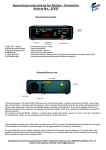
Elements of the front side
Temperature adjustment
Setpoint
Setting
Actual value
Calibration
Potentiometers
4 digit LED - display
Temperature ajustment knob
Calibration potentiometers
3 digit push-button switch
Mode selector
3 LEDs at the left
3 LEDs at the right
Red mode selector
shows the actual pH - value
has to be set to the temperature of the aquarium
are used for calibration
sets the pH - setpoint
set the control mode up/down
indicate the control mode up/down (red LEDs) and the state of the outlet (yellow LED)
indicate actual value is above or equal or below the setpoint
Elements of the rear side
Fuse holder
BNC jack
Outlet socket
Power cord
Connect the power cord with the 235 volts power net. Connect the pH - sensors connector to the BNC - jack at rear side.
Put the pH - electrode into the aquarium. Don’t submerse the electrode fully. The top of the electrode should be off the
water. Avoid stray current by bad isolated heaters or pumps in the aquarium. Even small voltages which do not affect the
creatures in the aquarium can damage the electrode rapidly. There is no warranty for electrodes ruined by this galvanic
process.
If you want to control the pH - value for a certain value a proper device like a pump or a valve has to be connected to the
outlet socket. (There are two examples showing how to control in this text)
The electrodes protection cap is filled with a special solution (KCL) to protect the electrode from becoming dry and aging.
If the electrode is not used for some time apply the cap again carefully removing any air bubbles.
For glas electrodes use the plastic protection tube by sliding the tube gently onto the electrode. The small holes in the
protection tube should be near the electrodes tip. By doing so your precious electrode will be protected from breaking.
Before calibrating remove the protection tube.
Operating instructions for pH - Controller
Article No.: 8/VII
Calibration:
With the measuring device comes a set of calibration solutions. This solutions should have the same temperature as
adjusted at the pH - meters front. If neccessary turn the rotary knob to adjust. Before calibration flush the electrode under
clear water. Fill the glass flasks half with pH7 and pH4 solution. Now dry the electrode cautiously with a clean cloth to
prevent dilution of the calibration fluid. As there are only some millilitres in each flask every drop of water at the tip of the
electrode will change the reading considerably. Now put the electrodes tip into the green pH7 - solution and wait for the
display to stabilise. This may take some minutes. Time increases as the electrode age. When the display has settled
adjust to 7.00 using the screwdriver with the left red adjustment potentiometer. Flush and dry the electrode again and put it
into the red pH4 - solution. When the display has settled adjust to 4.00 using the screwdriver with the right red adjustment
potentiometer. Trop Electronic devices are shipped already calibrated and ready to use. New devices should be
recalibrated approximately two weeks after setting up operation.
Examples:
Please observe for both examples
be cautious to start with low amount of gas or solution. Don’t place the pH - electrode to near to gas/solution outlet. Set
the 3 digit push-button switch to the desired pH-value. The outlets state is indicated by the left yellow LED. It will take
approx. 1 minute for the outlet (and the yellow LED) to be activated when the actual value is out of range. The outlet will
shut off immediately if the actual value runs into the “good” range. When the actual value crosses the setpoint (dependng
on the mode switch) the delay will start again. This delay is built in to enable mixing of water and gas/solution and to avoid
unnecessary switching of the valve due to choppy water, avoiding unnecessary noise etc. After 10 minutes on for the
outlet there will be a pause for 1 minute enabling the fluids to mix. The green LED (”>*<”) will be on when the pH - value
is equal to the setpoint.
Example 1: lowering the pH - value
The devices outlet has to be connected to a valve which controls the intake of carbon dioxide (Co2) into an aquarium.
The red mode control selector has to be pressed (in). Now the device will try to hold the pH-value to the selected setpoint.
If the pH-value is higher than the setpoint the upper right red LED (”>”) should be on. After approx. 1 minute the outlet will
switch on.
Example 2: increasing the pH - value
The devices outlet has to be connected to a dosing pump which controls the intake of liquid carbonate-bicarbonate into
an aquarium. The red mode control selector has to be released (out). Now the device will try to hold the pH-value to the
selected setpoint. If the pH-value is lower than the setpoint the lower right red LED (”<”) should be on. After approx. 1
Replacing the fuse
The fuse is in a holder above the power cord at the rear side of the device. The holder cap is released by turning it
counterclockwise. Be sure to disconnect the device from the powernet before opening the holder. The fuse has to
be replaced by the exactly the same rating.
Subject to change without prior notice.