1
XL”2T
Security System
Owner’s Manual
FIRE BURGWRY
INSTRUMENTS,
INC.
Technical Manuals Online! - http://www.tech-man.com
—
N9819 7/97
QUICK REFERENCE
SYSTEM
.............................................. .................................................................. 3
REFERENCE
.................................... ...................................... ...... ......... .............. ,,, , 5
TURNING
THE SYSTEM
ON ................. ....... .............................. ....................................... .... ... 7
TURNING
THE SYSTEM OFF .... ................................... .......................................................... 10
USER CODES ................................. .......................................................................................ll
MISCELMNEOUS
TESTING
COMMANDS
THE SYSTEM
RECOMMENDATIONS
EMERGENCY
GLOSSARY,
LIMITATIONS
LIMITED
.......................... ..................................................... .... ........... .. .. ...l4
ON SMOKE DETECTORS
EVACUATION
............................
.............................
FCC STATEMENT
............................. ................................................................l2
WARRANTY
............. ...................................................l6
............................................................................................l7
...............................
OF THIS AURM
............... ..... .............................................l5
............................................................... ................21
SYSTEM .......................
........................................................22
.............................
................................................................................24
Page 2
Technical Manuals Online! - http://www.tech-man.com
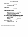
QUICK REFERENCE
TURN SYSTEM ON
. Check
to make sure the system is READY - Green ready hght is lit+
rlrln
. Enter your 4-digit user codem
. The On/Off (Arm) light will tight
* Exit through a door designated
TURN SYSTEM OFF
. Enter through
by your installer as an exiffentry
a door designated
. Enter your 4-digit user cod~l
by your installer as an exitientry
m
m
door
door
~
. The System On (Arm) hght will go out
TURN SYSTEM ON AND STAY INSIDE
. Check to make sure the system
is READY - Green ready light is lit+
Followed by your user code
. The OtiOff
m
m
m
m
(arm) light and the Stay light will both light
REMEMBER: You must turn the syetem off if you want to open the door or leave
the premises after the exit tima has passed.
TURNTHESYSTEM
ON: PERIMETERSENSORS
INSTANTMODEAND
STAY INSIDE
. Check to make sure the system is READY - Green ready tight is lit+
‘“’lowed
by
-
Followed by your user code
-
~
rl
m
❑
. The On/Off Hght, the Instant tight and the Stay light will all be on
SMOKE DETECTOR RESET
. Enter your 4-digit user
t
code
[1
rl
n
ready tight not available on all keypads
Page 3
Technical Manuals Online! - http://www.tech-man.com
~
INTRODUCTION
Congratulations
on your decision to protect your home or business with the
XL-2T security system. You have chosen a reliable, state of the art security
system that is remarkably easy to operate. Your eystem has been professionally
installed by your local Security Company who can explain the specifice of your
system.
The keypad is the input and dsplay device for your security system. The
following keypad models can interact with your system. Your Security Company
will suggest the model most appropriate for your premises and your needs.
XL4600SM -A sutiace mount keypad containing indicator lights for each of the 8
zones (areas of protection). The door covering the buttons is optional and can be
removed.
6615A surface mount keypad containing
possible zones (areas of protection).
The XL-2T is listed by Underwriters
appkcations.
indcator
Laboratories
for Household
Throughout this manual, the following conventions
keystrokes required to perform the functions.
m
m
m
m
lights for each of the 8
are
Hre and Burglary
used to display
the
Button labeled STAY
Button labeled BYPASS
Button labeled INSTANT
Button labeled CODE
❑ O•04-~git
user coda
Please keep your manual
needed.
in a convenient
Page 4
Technical Manuals Online! - http://www.tech-man.com
location
so you can
refer to it if
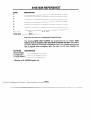
SYSTEM REFERENCE
ZONE
1
DESCRIPTION
2
3
4
5
6
7
Entry time
Door
EntW time
Door
Exit
time
Exit time is the same for all designated
Entry/Exit doors.
The following SEND HELP ALERTS are programmed into my system. Both
Buttons must be pressed st the same time to sctivate the aleti. The buttons
you press depend on which type of keypad you have. Your installer will show you
how to activate these emergency keys. The keys for LED style keypads are
shown below
BUTTONS
DESCRIPTION
[#]&~]
(Right+)
_
[~&[9](Lefi+)
_
[l]&[3](Cente+)
_
t Buttons on XL-4600SM
keypad only
Page 5
Technical Manuals Online! - http://www.tech-man.com
—
SYSTEM REFERENCE
USER ID
ASSIGNED TO
1
(MASTER USER ‘ )
2
(MASTER USER ‘ )
3
4
5
6
7
8
9
10
11
12
13
Door Sttike-Yes
No
If No
of user 13 is not assigned for door strike, then any user can ativate the door stdke)
14
Only Turns System On -Yes
If No
15
Ambush/Duress
Code -Yes
If No
‘Master
Users mn Add, Change, or Erase other user codes.
Monitoring
Station
Awount #
Telephone #
Information
Page 6
Technical Manuals Online! - http://www.tech-man.com
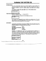
TURNING THE SYSTEM ON
SYSTEM
READY
You can turn the Burglar portion of your security system on and off. Before you
can turn the system on, it must be “reedy; If you hsve a protected door open, or
someone is moving in view of a motion detector, the system will not dsplay
“ready.”
The system
m
is ready If the ready light Is on or if the display
TURN THE SYSTEM ON AND LEAVE
Enter your 4-@git user code
ahowe:
❑ oon
The System On (Arm) tight will go on or the display will show
m
Exit through a door designated by your installer as an exitientry door. You must
leave within the exit time programmed by your installer. Refer to the reference
sheet for the time that has been set for your system.
NOT READY
If the system is not ready to be armed, the READY light will be off and the Zone
lights will show which zone or zones are not ready. The zone fights indicate the
following conditions, or the display will show as follows:
Faat
Slow
Slow
Solid
Blink
BlinWLow
Pulse
On
Intensity
Alarm
Bypass
Trouble
Not Ready
Example
If the Ready fight is not tit and the zone one light ia solid on. An
alarm sensor on zone one ia faulted. This might mean that a window is open or
someone is walking in view of a motion sensor. Check all sensors on zone one
and resolve the problem. When all sensors are restored, the Ready light will
come on and the zone tight will go out. In this example, the display shows:
SYSTEM
NOT READY
Page 7
Technical Manuals Online! - http://www.tech-man.com
—
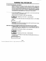
TURNING THE SYSTEM ON
TO TURN THE SYSTEM ON - NOT READY
Determine which zone or zones is not ready, resolve the problem, and turn the
system on normally. If the problem cannot be resolved, you may bypaaa the
zone that is not ready. Bypassing should only be done if the problem on the zone
cannot be resolved, OR if you intentionally wish to leave the zone off, Example
you wish to keep the window open for ventilation, Zones that are bypassed are
not protacted when the systam ia on. See Bypass for the procedure.
TURN SYSTEM
ON AND STAY fNSIDE
To turn the perimeter potion of your burglar alarm on and move around freely
inside the premises, use the STAY mode.
Check to make sure the system is ready when raady press:
m
If successful,
shows
Followed by your user code
the OtiOff
❑ unn
(arm) light and the Stay tight will be lit, or the” display
~
REMEMBER: You must turn the system off if you want to open the door or leave
the premises after the exit time haa passed.
TURN THE SYSTEM ON: PERIMETER SENSORS INSTANT MODE AND STAY fNSIDE
In fNSTANT STAY mode, the parimeter potiion of your burglar alarm system is
on and the time delays are eliminated from your normal ent~/exit door(s), All
interior protection is off so you are free to move around inside.
Check to make sure the system is READY, when ready press
m
‘“’’owed
m
Followed by your user code
If successful, the OtiOff
the dsplay ahowa:
ON: STAY INSTANT
by
m
m
m
rl
fight, the Instant light and the Stay light will all be on, or
[
Psgs
s
Technical Manuals Online! - http://www.tech-man.com
T(VRNING THE SYSTEM ON
TURN THE SYSTEM ON WITH ALL SENSORS IN INSTANT RESPONSE MODE
In INSTANT
mode, all alarm sensors will repoti an alarm immediately
if
activated, including the doors that normally have adelayto
allow youto turn the
system oti. Chackto make eurethe system is ready when ready press
ED
If successful,
shows.
Followed byyour
the On/Off
usercode
mmmrl
light and the Inetant light will be on, or the display
BYPASS
Bypass excludes a zone of protection from the security system until it is
unbypsssed (either by using the unbypaes procedure or when you turn the
eystem off). Bypassing can only be done while the system is turned off.
Press the Bypass Button followed by your user code and then the zone number
(l-7) to be bypassed.
m
Followed byyour
usercode+
rlmmr{
+
ZONE#
+ If the “Quick Bypass” feature has been enabled by the installer, the user code is
not required when bypassing zones.
NOTE: Bypassed zones are not protected when the system is turned on. After
the bypass command has been accepted, the keypad will sound one long beep,
and the zonetight of the zone(s) bypassed will slowly blink, or the display shows:
IMPORTANT: Temporary users ~.e, baby sifters, housekeepers,
be shown the Bypass procedure.
etc.) should not
UNBYPASS
Unbypass returns a bypassed zone to normal operation.
repeat the bypass function.
m
Followed byyourusercode
After unbypassing
a zone(s),
rlnrlrl+ ZONES
the zone display will show the state of the zones.
Pages
Technical Manuals Online! - http://www.tech-man.com
—
To unbypass
TURNING THE SYSTEM OFF
When you turn off the system, you turn off only the burglar portion of
system; any smoke or heat detators and panic buttons will remain on. You
enter through a designated entry door and turn off the system within the
allowed. You can have different amounts of time for dfferent entry points.
your system reference sheet for the times established for your system.
your
must
time
See
To turn yuour system off
Enter your 4-digit user code
L—lr]
rl
rj
If no alarms have teken place, the On/Off
display shows
tight (labeled arm) will go off, or the
If alarms occurred when the system was on, or if a trouble condition
will display on the zone indcator lights as follows
Faat Btink
Slow BlinWLow
slow Pulse
Solid On
or
exists, they
Alarm
Bypass
Trouble
Not Ready
Intensity
the display shows
Burgla~ Alarms will sound a steady sound at tha keypad(s),
generate a pulsing sound.
and fire alarms will
Important
If an intrusion has taken place while you were away, do not enter
until the location has been checked. Call for help from a neighbor’s house and
wait for the potice,
After you have turned the system
display keypads will show
off with your user code,
the message
on
m
To clear the display of the alarm or trouble conditions
alert :
Enter your 4-digit user code
n
~
Page 10
Technical Manuals Online! - http://www.tech-man.com
r!
rj
again.
and silence
the audible
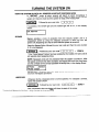
USERCODES
ADDORCHANGE
AUSERCODE
Users csn be added or changed directly at the keypad. Your system can have up
to 15 different user codes. Users #1 and #2 are the only users allowed to add or
delete other users.
Press the Code button followed by user #1 or user #2 ~digit user code, then the
new user’s user number and the new 4-digit user code. The keypad will beep
after each dgit is pressed.
User #1 or #2 Ctie
=1
❑
UUU
User ID
nn
New User Code
nnnn
Use the system reference sheet to record system users. On this sheet your
installer will indicate if you heve chosen to dedicate a user code to send an
emergency signal in the case of Ambush or Duress, You may also have chosen
to resewe one user code that is only allowed to turn the system on. This code
will not be able to turn the system off.
DELETE
A USER CODE
To delete a user, press the Code button followed by the 4-digit master user code,
then the user number, then press [#] to delete. For example, to delete user 3, do
the following
Master User C@e
User 10
#to delete
NOTE: User #1, the master usar, cannot be deleted but it can be changed
the ADD OR CHANGE user procedure.
TURN SYSTEM
ON ONLY (Maid Code)
If you choose to have a code thet cannot turn the system off, but can turn the
system on, have your installer program this festure.
If programmed, user code
14 will have System On capabihty only, and you can issue this code to a
temporary ueer ao they can secure the premises when they leave.
Page 11
Technical Manuals Online! - http://www.tech-man.com
—
using
MISCELLANEOUS COMMANDS
KEYPAD,
SEND HELP CONDITIONS
Your system can be programmed for 3 separate “Send Help” alerts which would
send an emergency signal to your central station. See the System Reference
sheet to see which have been programmed for your system.
DURESS
Your system can be programmed to send anemergency
signal to the Central
Station if you are forced to enter the premises. If you choose to include this
feature, User Code number 15 is dedicated to this function and must only be
used under a dureaa circumstance.
QUICK ON - (QUICK ARMING)
If programmed by your installer, Quick On, or Quick Arming, allows you to turn
the system onto the away mode without user code. NOTE: Turning your system
Off always requires a vatid User Code.
Press [#] then
QUICK
FORCED
[1]
ON
If programmed by your installer, Quick Forced On allows you to turn the bu’rglar
portion of your alarm system on to the away mode, bypassing all zones that are
not ready.
Press [#] then
[2]
NOTE: A va~d user code ia still required to turn the system off.
NOTE
TMs feature is disabled on UL installations.
QUICK BYPASS
If you hava quick bypass programmed for your system, you will not have to use
your user code to bypass zones. The quick bypass procedure is
ZONE
(l-7)
NOTE: Bypassed zones are not protected when the system is turned on. After the
bypass command has been accepted, the keypad sounds one long beep, and tha
zone tight of the zone(s) bypaaaed will slowly bhnk, or the display will show:
=
NOTE: Temporary
procedure.
users fi.e. baby sitters, housekeepers,
Page 12
Technical Manuals Online! - http://www.tech-man.com
“-
etc.) should not be shown the Bypass
MISCELLANEOUS COMMANDS
TURN CHIME OWOFF
Chime is an optional feature that causes tha keypad to chime when selected
doors are opened while the burglary protection is off or disarmed.
Only your installer can program a zone for the chime feature, but once
programmed, you can turn chime on or off to meet your daily needs, To turn
Press [#] then [6]
chime on or off:
SET AUTO ON TIME
Set Auto On Time lets you set the time your system will automatically
Press
[#]
then
[5]
[user 1 or 2 code]
[hr] [hrJ
[mini
turn on.
[rein,]
The English read out keypad will prompt you for the required entries.
(user code is not required if so programmed by installer)
DOOR STRIKE
To acfiiate
Press
[#]
door strikes
then
[9] [user code]
[Door #]
(Note that ths installer may have
aeaigned user 13 as the only user that
can perform the door etrike function.)
where the door number is as follows
1
2
VIEW TIME
[#l [m
SET TIME
[#] [3] [user 1 or 2 code] [hr,] [hr,] [mini,]
[year,] [year,]
(user code is not required if so programmed
[min,l
[mnth,l
by installer)
VIEW AUTOARM .TIME
[#] .[8] [user 1 or 2 code]
m
(user code is not required if so programmed
Page 13
Technical Manuals Online! - http://www.tech-man.com
by installer)
[mnth,l
[day,]
[dayJ
TESTING THE SYSTEM
SYSTEM TEST
It is recommended that you teet your system once a week using the following procedure
NOTE: If your system is monitored, contact your Central Station before you perform this test.
1. Turn your Security System on.
2. Wait until your exit time is over and them activate the system by opening a protected zone.
(For example a window or door).
3. Confirm that the alarm sounding device (bell or siren) sounds. If your system is connected to
a central station the keypad will sound the ringback tone to confirm that the signal was
received.
4. Turn the Security System off.
5. Call the Central Station to tell them you are done testing.
BA~ERY
TEST
It is recommended that you test your Battery once a month. In order to teat your backup/standby
battery, the following procedure should be followed
1. Unplug the transformer from the AC outlet by removing the restraining screw which secures
the transformer to the wall, (Note the screw is not present on the models sold in Canada.)
2. Obsewe that the AC indicator fight on the keypad goes off.
3. Activate your alarm by performing the above SYSTEM TEST. Remember to contact your
Central Station if your system is monitored.
4. Plug the transformer into the AC outlet and secure with the restraining screw. (Note the screw
is not present on the models sold in Canada.)
The National Fire Protective Association publishes a standard for fire warning equipment (NFPA
pub~cafion #74). Further information can be obtained by contacting: NFPA Pubtic Affairs Dept.,
Batfe~march
Park, Quincy, MA 02269.
If you have any further questions about the operation of your system, please contact your alarm
company.
Page 14
Technical Manuals Online! - http://www.tech-man.com
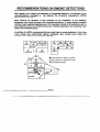
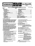
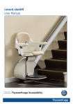
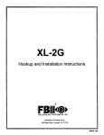
RECOMMENDATIONS ON SMOKE DETECTORS
With regard to the numbar and placement of amoktieat
detectors, we aubacribe to the
the Netional Fire Protection
Association’s
(NFPA)
recommendations
containad
in
Standard #74 notad below.
Early warning fire detection
ia beat achieved
by tha installation
of fire detection
equipment in all rooms and area of the household aa follows: A smoke detactor installsd
outside of each separate alaaping area, in the immediate vicinity of the bedrooms and on
each additional story of the family living unit, including basements and excluding crawl
epacea and unfiniahad attics.
In addition, the NFPA recommends that you install heat or smoka detectors in the living
room, dining room, bedroom(s),
kitchen, hallway(s),
attic, furnace room, utility and
storage rooms, basemerlta and attached garagea.
o
0
o
BEDROOM
BEDRWM
LIVINGROOM
a
4
L
BEOROOM
❑
Smoke Det@om for Mnimum Protection
O
Smoke Datetiom for Additional Protection
A
Heat-Activated Detectom
LVNG RM
❑
BASEMENT
Page 15
Technical Manuals Online! - http://www.tech-man.com
—
EMERGENCY EVACUATION
Establish and regularly practice a plan of escape in the event of fire. The following steps are
recommended by the National Rre Protection Association:
1. Position you; detector or your interior and/or esterior sounders so that they can be heard by
all occupants.
2. Determine two means of escape from each room. One path of escape should lead to the
door that permits normal exit from the building. The other may be a window, should your
path be unpassable.
Station an escape ladder at such windows if there is a long drop to the
ground,
Show windows, doors, stairs and rooftops that can be
3. Sketch a floor pan of the buil~ng.
used to escape.
Indcate escape routes for each room.
Keep these routes free from
obstruction and post copies of the escape routes in every room.
4. Assure that all bedroom doors are shut while you are asleep. This will prevent deadly smoka
from entering while you escape.
5. Try the door. If the door is hot, chack your alternate escape route. If the door is cool, open it
cautiously. Be prepared to slam the door shut if smoka or heat rushes in.
6. When smoke is present, crawl on tha ground, Do not walk upright, since smoke rises and
may overcome you. Clearer air is near the floor.
7. Escape quickly don’t panic.
6. Establish a common meeting place outdoors, away from your house, where eve~one can
meet and then take ataps to contact the authorities and account for those missing. Chooses
someone to assure that nobody returns to the house — many die going back.
Page 16
Technical Manuals Online! - http://www.tech-man.com
GLOSSARY
AC INDICATOR:
Small green light between the center buttons on the keypad. When lit, the
eystem is running on electricity when not lit, the system is running on the backup batte~.
ALARM: Sound from keypad or other horn/siren indicates a burglar alarm, fire alarm or other
cond!tion you should be alerted to.
ARMED See ON/OFF
AWAY Asystem setting that protects the premises while it is unoccupied. All burglary sensors
are active.
BURGLARY/FIRE:
Thetwomajor
functions of a Secufity System. Fire protection is always on
and cannot be turned off The Burglary sensors protect against unauthorized entry into your
premises. The Burgla~ protection can be turned on and off and programmed for special levels of
access and notification.
BYPASS FEATURE
The Bypass Feature allows you to exclude a selected zone or zones from
the burglar alarm protection.
BYPASS BU~ON:
A button on the keypad used to activate the Bypass Feature.
CENTRAL
STATION: Signal Monitoring Center contacted by your Security System over the
telephone and/or other communication
channels when alarms are activated if your system is
programmed to communicate alarms off site. The Central Station will follow their procedures and
your instructions for contacting the proper authorities when a signal is received.
CHIME FEATURE
An optional feature that causes the keypad to chime for one second when
selected doors are opaned when the burglary protection is off or disarmed. Once programmed by
your installer you can turn chime on and off with #6.
DISARMED
See ON/OFF.
DURESS: Duress is a system feature the you may have programmed
into your system. If
someone should force you to turn your system off, you would use the special Duress user code
and the system would turn off and it would also send a silent duress emergency to the Central
Station so they could respond appropriately.
ENTRY DELAY: The pefiod of time allowed between opening a designated enty/exit
door and
turning off the alarm system before the system will register an alarm condition. This is determined
at the time of installation. Your system suppotis two entry times allowing you to have a different
length of time for different doors.
EXIT DELAY The period of time allowed between turning the system on and leaving through a
designated exitient~ door. This is determined at the time of installation.
INTERIOR ZONE: An interior zone is a group of points that protect the interior of your premises.
You may want to turn the perimeter portion of your system on while leaving the interior zones off
allowing you to move freely inside, opening interior doors and passing by motion detectors
without causing an alarm.
KEYPAD A Keypad is your link into your system. It dsplays alarm and trouble messages, shows
faulted zones and allows you to turn the system on/off by using the buttons. Your system will
have one or more keypads.
Psgs 17
Technical Manuals Online! - http://www.tech-man.com
GLOSSARY
OWOFF: These terms refer to the burglary portion of your security system. There are several
levels of operation which allow you to protect part of your premises while you remain inside. Fire
sensors and other emergency and environmental conditions are always active and ready and are
not affected in any way by turning the burglary portion of your Security System on or off. Armed,
s term that is sometimes
used meana system on and Disarmed means system off. See
ON-INSTANT, ON-STAY and STAY.
OWOFF INDICATOR
Red tight in the upper portion of the keypad labeled Armed. When tit,
some part of the burglar alarm system is on; when not lit, the burglary potion of the system is off.
ON-STAY
A system setting that turns on the perimeter protection of the building but allows
movement throughout the inside.
PANIC BUTTON: A push button which allows you to signal the Central Station that you need
immediate asaiatance. Your system has programmable Keypad Send Help Alefls which can also
sewe as Panic buffona.
PERIMETER
ZONE: A perimeter zone is a group of points that” protect the exterior of your
premises. Your outside doors and windows would be programmed as a perimeter zone.
SENSOR: The actual alarm sensor, detector or device installed to detect an intrusion, fire, or
environmental
problem. Examplea include door contacts, window contacts, motion sensors,
glass break sensors, smoke detectors,
rate of rise heat detectors,
temperature
sensors,
floo~water sensors, and carbon monoxide gas detectors.
SILENT CONDITION: Most types of alarms and troubles alert you with the keypad sounder and
the sirens, horns, or speakers located in your premises. The intent is to advise you of the alarm
or trouble and allow you to respond promptly. The audible sounds also let an intruder know that
they have baen detected and will hopefully scare them away. In some circumstances,
an audible
alarm might put your life in danger and so those alarms are programmed as silent conditions. For
an example see DURESS.
SYSTEM: Your Security System ia composed of three main parts 1) the Control Panel which
functions as the system brain end the link to the Monitoring Agency (Central Station), 2) the
Keypad(s) which provide you with system status and allow you input commands,
3) Security
Sensors such as door and window contacts, motion sensors, smoke detectors and other sensors
as required to detect intrusion, fire and other conditions as needed for your premises.
USER CODE: A user code is a 4 digit code which ia required to operate the system. The system
supports up to 6 separate user codes. The system supports one master user who can adddelete
other user codes. Two of the user codes may be dedicated to special functions as defined by
your alarm company at the time of installation. (See the User Code Ust in the back of this
manual)
ZONE: A zone is a collection of aensora with common characteristics grouped together for your
operating convenience. The system will support 6 zones or groupings.
Page 18
Technical Manuals Online! - http://www.tech-man.com
NOTES
Page 19
Technical Manuals Online! - http://www.tech-man.com
NOTES
Page 20
Technical Manuals Online! - http://www.tech-man.com
FEDERAL COMMUNICATIONS COMMISSION
(FCC) STATEMENT
This equipment haa baen tested to FCC requirements and has been found acceptable for use. The FCC
requires the following statement for your information:
This equipment generates and uses radio frequency energy and if not installed and used properly, that is.
in strict accordance with the manufacturers instructions, may cause intetierence to radio and television
reception. It has been type tested and found to comply with the hmits for a class B computing device in
accordance with the specification in Subpart J Pati 15 of FCC Rules, which are designed to provids
reasonable protection against such interference in a residential installation. However, there is no guarantee
that interference will not occur in a particular installation. If this equipment does cause interference to radio
or television reception, which can ba determined by turning the equipment on, the usar is encouraged to
try and correct tha intefierence by one or more of the following measures:
If using an indoor antenna, have a quality outdoor antenna installed.
Re-orient the receiving antenna until intetierence is reduced or eliminated.
Move the receiver away from any wire runs to the controllcommunicator.
Plug the controllcommunicator into a different outlet so that it and the receiver are on diffarant branch
circuits.
If necessary, the user should consult the dealer or an experienced ratioltelevieion technician for additional
suggestions.
The user or installer may find the following booklet prepared by the Federal Communication Commission
helpful: “interference HandbooW.
This booklet ia available from the U.S. Government Printing Offica, Washington, DC 20402.
The ussr shall not make any changes or modifications to the equipment unlese authorized by the
installation Inatructiona or User’s Manual. Unauthofizad changee or modifications could void the user’s
authority to operate the equipment.
TELEPHONE OPERATIONAL PROBLEMS
In the event of telephone operational problems, disconnect the control by removing the plug from the
RJ31X wall jack. We recommand that your certifiad installer demonstrate disconnecting the phones on
installation of the ayatem. Do not disconnect the phone connation inside the controVcommunicator. Doing
so will rasult in the loss of your phone tines. If the regular phone works correctly after the
contmUcommunicator has been disconnected from the phone Knas, the contmllcommunicator has a
problem and should be returned for repair. If upon disconnection of tha contro~communicator, there is still
a problem on the tine, notify the telephone company that they have a problem and raquest prompt repair
sewice. Tha user may not under any circumstances on or out of warranty) attampt any sewice or rapairs
to tha systam. It must be returned to the factory or an authorized sewice agency for all repairs. SYSTEM
TESTING
This control unit was manufactured under rigid quality standarda and compliaa with all UL
requirements for its intended use. Maintenance is best performed by your installing company with
trained sewice paraonnel.
Pags 21
Technical Manuals Online! - http://www.tech-man.com
—
LIMITATIONS OF THIS ALARM SYSTEM
While this system is an advanced design security system, it does not offer guaranteed protection
against burglaW, fire, or other emergency. Any alarm system, whether commercial or residential,
is subject to compromise or failure to warn for a variety of reasons. For example
Intruders may gain access through unprotected openings or have the technical sophistication to
bypass an alarm sensor or disconnect an alarm warning device.
Intrusion detectors (e.g. passive infrared detectors), smoke detectors, and many other sensing
devices will not work without batteries, or if the battaries are not put in properly. Devicee powered
solely by AC will not work if their AC power supply is cut off for any reason, however briefly.
Signals sent by wireless transmitters maybe blocked or reflected by metal before they reach the
alarm receiver. Even if the signal path has been recently checked during a weekly test, blockage
can occur if a metal object is moved into the path.
A user may not be able to reach a panic or emergency button quickly enough.
While smoke datectors have played a key role in reducing residential fire deaths in the United
States, they may not activate or provide early warning for a variety of reasona in as many aa 35Y.
of all fires according to data published by the Faderal Emergency Management Agency. Some of
the reasons smoke detectors usad in conjunction with the System may not work are as follows
Smoke detectors may not sense fires that start where smoke cannot reach the detactors, such ae
in chimneys, in walls, or roofs, or on the other side of closed doors. Smoke detectors also may
not sense a fire on another level of a residence or building. A second floor detector, for example,
may not sense a first floor or basemant fire. Moreover, smoke detectors have sensing imitations.
No smoke detector can sense every kind of fire eve~ time. In general, detectors may not always
warn about fires caused by carelessness
and safe~ h=ards
like smoking in bed, violent
explosions, ascaping gas, improper storage of flammable matetials, overloaded electrical circuits,
children playing with matches, or arson. Dependng on the nature of the fire andor the location of i
the smoke detectors, the detector, even if it operates as anticipated, may not provide sufficient
warning to allow all occupants to escape in time to prevent injury or death.
Passive Infrared Motion Detectors can only detect Intrusion within the designed ranges as
diagramed
in their Installation Manual. Passive Infrared Detectors do not provide volumetric
area protection. Theydo create multiple beams of protection, and lntrueion can only be detected
in unobstructed areas covered by the beams. They cannot detect motion or intrusion that takes
place behind walls, ceihngs, floors, closed doors, glass partitions, glass doors or windows.
Mechanical tampering, masking, painting or spraying, of any material on the mirrors, windows or
any pati of the optical systam can reduce their detection abitity. Passive Infrared Detectors sense
changes in temperature
however, aa the ambient temperature of the protected area approaches
the temperature range of 90 degrees to 150 degrees Fahrenheit, the detection performance can
decrease.
Page 22
Technical Manuals Online! - http://www.tech-man.com
LIMITATIONS OF THIS ALARM SYSTEM
Alarm warning devices such as sirens, bells or horns may not alert people or wake up sleepers
who are located on the other side of closed or patily open doors. If warning devices sound on a
differant level of the residence from the bedrooms, then they are less fikely to waken or alefl
people inside the bedrooms. Even persons who are awake may not hear the warning if the alarm
is muffled by noise from a 3tereo, radio, air conditioner, other appliances, or by passing traffic.
Rnally, alarm warning devices, however loud, may not warn hearing-impaired
people or waken
deep sleepers.
Telephone Inca naeded to transmit alarm signals from a premises to a central monitoring station
may be out of service or temporarily out of aewice. Telephone tines are also subject to
compromise by sophisticated intruders.
However, even if the system responds to the emergency as intended
occupants may have
insufficient time to protect themselves from the emergency situation. In the caae of a monitored
Ialarm system, euthorifies may not respond appropriately.
Ttis equipment, like other electrical devices, ie subject to component failure. Even though this
equipment is designed to last as long as 10 years, the electronic components could fail at any
time.
The most common cause of an alarm system not functioning when an intrusion or fire occurs in
inadequate maintenance. This alarm system should be tested weekly to make sure all sensors
are working proparly.
Instalhng an alarm system may make one ehgible for lower ineurance rates, but an alarm system
is not a substitute for insurance, Homeowners, property owners and renters should continue to
act prudently in protecting themselves and continue to insure their fives and propetiy.
We continue to develop new and improved protection devicee. Users of alarm systems owe it to
themselves and their loved ones to learn about these developments.
Page23
Technical Manuals Online! - http://www.tech-man.com
I
I
I
LIMITED WARRANTY
Fire Burglary lnatrumants, inc.,, a aubaidia~ of Pittway Corporation, and Rttway Corporation, its divisions,
subsidiaries and affiliate ~Seller”), 149 Ellaen Way, Syosaet, New York 11791, warrants its aecutity
equipment (the “product”) to be free from defects In material and workmanship for one ysar from date of
otiginal purchaae, under normal use and sewice. Sallete obligation is fimited to repaiting or replacing, at its
option, free of charge for pana, labor, or transportation, any product proved to be defectiva in matetiak or
wotimanstip
under normal uae and sewice. Seller shall hava no obligation under this warranty or
othewise if tha product is altered or impropar[y repaired or aewiced by anyone other than the Seller. In
case of defee!, contact the security profeeeional who installed and maintains your secudty equipment or
the Seller for product repair.
This one year Limited Warranty ia in lieu of all other expressed warranties, obhgationa or Uabitities. THERE
ARE NO EXPRESS WARRANTIES, WHICH ExTEND BEYOND THE FACE HEREOF. ANY IMPLIED
WARRANTIES, OBLIGATIONS OR LIABILITIES MADE BY SELLER IN CONNECTION WITH THIS
PRODUCT, INCLUDING ANY IMPLIED WARRANTY OF MERCHANTABILITY, OR FITNESS FOR A
PARTICULAR PURPOSE OR OTHERWISE, ARE LIMITED IN DURATION TO A PERIOD OF ONE YEAR
FROM THE DATE OF ORIGINAL PURCHASE, ANY ACTION FOR BREACH OF ANY WARRANTY,
INCLUDING BUT NOT LIMITED TO ANY IMPLIED WARRANTY OF MERCHANTABILITY, MUST BE
BROUGHT WITHIN 60 MONTHS FROM DATE OF ORIGINAL PURCHASE, IN NO CASE SHALL SELLER
BE LIABLE TO ANYONE FOR ANY CONSEQUENTIAL OR INCIDENTAL DAMAGES FOR BREACH OF
THIS OR ANY oTHER WARRANTY, EXPRESS OR IMPLIED, OR UPON ANY OTHER BASIS OF
LIABILITY WHATSOEVER, EVEN IF THE LOSS OR DAMAGE IS CAUSED BY THE SELLERS OWN
NEGLIGENCE OR FAULT. Some atatea do not allow hmitation on how long an imphed warranty Iasta or
the exclusion or limitation of incidental or consequential damagas, so the above limitation or exclusion
may not apply to you.
Seller
prevent
does not represent
any personal
that the product
inju~
or propatiy
may not be compromised
Iosa by burgla~,
robbe~,
or circumvented;
fire or otha~iae;
that the product
or that the prodwt
will
will
in all cases provide adequate warning or protection. Buyer underetanda that a properly installed and
maintained alarm may only reduce tha tiak of a burgla~, robbery, fire or other eventa Wcuming without
providing an alarm, but it ia not insurance or a guarantee that such will not occur or that there will be no
personal inju~ or propetiy loss aa a result. CONSEQUENTLY, SELLER SHALL HAVE NO LIABILITY FOR
ANY PERSONAL INJURY, PROPERTY DAMAGE OR OTHER LOSS BASED ON A CLAIM THE
PRODUCT FAILED TO GIVE WARNING, HOWEVER, IF SELLER IS HELD LIABLE, WHETHER
DIRECTLY OR INDIRECTLY, FOR ANY LOSS OR DAMAGE ARISING UNDER THIS LIMITED
WARRAN~ OR OTHERWISE, REGARDLESS OF CAUSE OR ORIGIN, SELLERS MAXIMUM LIABILITY
SHALL NOT IN ANY CASE EXCEED THE PURCHASE PRICE OF THE PRODUCT, WHILE SHALL BE
THE COMPLETE AND EXCLUSIVE REMEDY AGAINST SELLER. This warranty gives you spacific legal
tights, and you may also have othar righte whtch va~ from etate to state. No increase of alteration, wfitten
or verbal, to this warranty ia authorized.
FIREeURGLARYINSTRUMENTS,INC.
Technical Manuals Online! - http://www.tech-man.com