1
Installation and user’s guide
H-2000-5009-04-A
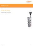
MP16 probe system with
selectable channel radio transmission
© 1999 – 2002 Renishaw. All rights reserved.
Renishaw® is a registered trademark of Renishaw plc.
This document may not be copied or reproduced in whole or in part, or
transferred to any other media or language, by any means, without the prior
written permission of Renishaw.
The publication of material within this document does not imply freedom from
the patent rights of Renishaw plc.
Disclaimer
Considerable effort has been made to ensure that the contents of this document
are free from inaccuracies and omissions. However, Renishaw makes no
warranties with respect to the contents of this document and specifically
disclaims any implied warranties. Renishaw reserves the right to make changes
to this document and to the product described herein without obligation to notify
any person of such changes.
Trademarks
All brand names and product names used in this document are trade names,
service marks, trademarks, or registered trademarks of their respective owners.
Renishaw part no: H-2000-5009-04-A
Issued: May 2002
H-2000-5009-04-A
Installation and user’s guide
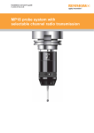
MP16 touch–trigger
probe system
(MP3 probe with selectable
channel radio transmission)
2
Information in this document is subject to change without notice. No part of this document may be reproduced or transmitted in
any form or by any means, electronic or mechanical, for any purpose, without the express permission of Renishaw plc.
CHANGES TO EQUIPMENT: Renishaw reserves the right to change its equipment without obligation to change equipment
previously sold.
WARRANTY: Equipment requiring attention under warranty must be returned to your supplier. No claims will be considered
where equipment has been incorrectly installed or misused, or where repairs or adjustments have been attempted by
unauthorised persons. Prior consent must be obtained in instances where Renishaw equipment is to be substituted or omitted.
Failure to comply with this requirement will invalidate the warranty
PATENTS: Features of the Renishaw MP16 touch-trigger probe system (MP3 probe with channel selectable radio
transmission) are subject to the following patents and patent applications:
EP 0506318
EP 0652413
EP 0872787
EP 108521
JP 1,847,335
JP 1,942,442
JP 2,514/1999
JP 3,126,797
US 4542467
US 4599524
US 4636960
US 5,272,817
US 5,279,042
This product has been tested to the following European Standards:
I-ETS 300 220 (October 1993)
ETS 300 683 (June 1997)
It complies with the relevant essential health and safety protection requirements of the following EC Directives:
89/336/EEC, 91/263/EEC, 92/31/EEC (EMC), 93/68/EEC (CE Marking)
All relevant safety information, including that incorporated in this Installation and User’s Guide must be observed.
FCC
Information to User (FCC Section 15.19)
This device complies with Part 15 of the FCC rules. Operation is subject to the following conditions:
1. This device may not cause harmful interference.
2. This device must accept any interference received, including interference that may cause undesired operation.
Information to User (FCC Section 15.105)
This equipment has been tested and found to comply with the limits for both a Class A and Class B digital device, pursuant to
Part 15 of the FCC rules. These limits are designed to provide reasonable protection against harmful interference when the
equipment is operated in a commercial environment. This equipment generates, uses and can radiate radio frequency energy
and, if not used in accordance with this Installation and User’s Guide, may cause harmful interference to radio communications.
Operation of this equipment in a residential area is likely to cause harmful interference, in which case you will be required to
correct the interference at your own expense.
Information to User (FCC Section 15.21)
The user is cautioned that any changes or modifications, not expressly approved by Renishaw plc or authorised representative,
could void the user’s authority to operate the equipment.
Special accessories (FCC Section 15.27)
The user is cautioned that any peripheral device installed with this equipment, such as a computer, must be connected with a
high-quality shielded cable to ensure compliance with FCC limits.
3
FCC (continued)
The FCC has assigned the following product information codes:
FCC ID: KQG RMP2-224
Comprising:
RMP2 radio module probe (transmitter)
MP3 touch-trigger probe
FCC ID: KQG MI16-224
Comprising:
MI16 machine interface (receiver)
RMM2 radio module machine (antenna)
RMM2 radio module machine (antenna)
OM16 optical module (optional)
PSU3 power supply unit (optional)
Radio authority approval
The 433 MHz variant of this product conforms to I-ETS 300 220 (October 1993), BAPT 222ZV 125 Dec. 1994 and Directive
89/336/EEC.
The product complies with the R&TT Directive 1999/5/EC of 09. March 1999.
The product is approved by, and has been assigned the registration number quoted, within the following countries:
Denmark:
Finland:
France:
Germany:
Holland:
Sweden:
Switzerland:
Registration number – CEPT/LPD/DK/9853
Registration number – FI98080066
Registration number – 98 0102 PPL 0
Registration number - G133598J
Registration number – G133598J, CEPT 433
Registration number – Ue980077
Registration number – BAKOM 98.0448.K.P
4
Table of contents
Table of contents
BEFORE YOU BEGIN.............................................................................................. 54
Support services.....................................................................................................................................56
The Renishaw Group world-wide .......................................................................................................56
The Renishaw product support network.............................................................................................56
Product support world-wide................................................................................................................56
Product support within the United Kingdom and Republic of Ireland .................................................57
Calling a Renishaw subsidiary company............................................................................................57
Renishaw subsidiary companies ........................................................................................................58
Renishaw’s MP16 touch-trigger probe system (MP3 probe with selectable channel
radio transmission).................................................................................................................................59
CHAPTER 1 - SYSTEM DESCRIPTION
Description of the MP16 touch-trigger probe system (MP3 probe with selectable channel radio
transmission).........................................................................................................................................1-2
The RMP2/RMP2-S...........................................................................................................................1-4
The RMP2 .....................................................................................................................................1-4
The RMP2-S..................................................................................................................................1-8
The MP3 touch-trigger probe ..........................................................................................................1-10
The kinematic location ................................................................................................................1-12
The MI16 .........................................................................................................................................1-13
The MI16 front panel ...................................................................................................................1-14
The MI16 rear panel ....................................................................................................................1-16
The RMM2.......................................................................................................................................1-18
The OM16 .......................................................................................................................................1-19
The shank adaptor ..........................................................................................................................1-20
The shank .......................................................................................................................................1-22
The PSU3........................................................................................................................................1-23
Technical data .....................................................................................................................................1-24
MP3 touch-trigger probe – technical specification ..........................................................................1-24
Probe dimensions........................................................................................................................1-24
Probe specification ......................................................................................................................1-25
RMP2/RMP2-S – technical specification.........................................................................................1-26
Transmission frequencies - Europe ............................................................................................1-27
Transmission frequencies – USA and Japan ..............................................................................1-28
Transmission frequencies – United Kingdom .............................................................................1-29
CHAPTER 2 – SYSTEM INSTALLATION
Installing the MP16 touch-trigger probe system on your machine tool..................................................2-2
Mounting the RMP2 to a shank .........................................................................................................2-3
Mounting shank adaptor (part no. A-2056-0979) to the RMP2 .....................................................2-4
Mounting shank adaptor (part no. A-2056-0979) to the shank......................................................2-6
Mounting shank adaptor (part no. M-2056-0293) to the RMP2.....................................................2-8
Mounting the RMP2-S to a shank ...................................................................................................2-12
Mounting the shank adaptor (part no. M-2056-0293) on a shank incorporating a shank switch 2-12
Mounting the shank adaptor and attached shank on the RMP2-S..............................................2-15
Programming the transmission channel and activation method of the RMP2/RMP2-S..................2-20
Connecting the MI16 to a temporary 24 V dc power supply........................................................2-20
Programming the MI16................................................................................................................2-24
Fitting batteries into the RMP2/RMP2-S .....................................................................................2-26
Table of contents
5
Programming the RMP2/RMP2-S...............................................................................................2-28
Positioning the RMM2s ...................................................................................................................2-31
Mounting the RMM2 radio module machines on the machine tool.................................................2-35
Mounting the MI16 on the machine tool..........................................................................................2-38
Cutting a hole in the mounting panel...........................................................................................2-39
Panel mounting the MI16 ............................................................................................................2-40
Connecting the RMM2 radio module machines to the MI16 ...........................................................2-42
Extending the RMM2 radio module machine cables...................................................................2-42
Fitting flexible conduit to the RMM2 radio module machine cables ............................................2-43
Mounting the optional OM16 on the machine tool ..........................................................................2-46
Mounting the OM16 directly on the machine tool guarding.........................................................2-48
Mounting the OM16 on the machine tool guarding/bulkhead using the mounting bracket .........2-50
Fitting flexible conduit to the OM16 cable ...................................................................................2-52
Connecting the OM16 to the MI16 ..................................................................................................2-54
Connecting the MI16 to the machine tool CNC controller and 24 V power supply .........................2-56
MI16 outputs ...............................................................................................................................2-56
Connecting the MI16 to the machine tool’s CNC controller ........................................................2-57
Connecting the MI16 to the machine tool’s 24 V power supply ..................................................2-60
Mounting the optional PSU3 on the machine tool ...........................................................................2-63
Connecting the optional PSU3 to the mains power supply .............................................................2-64
Mounting the RMP2/RMP2-S on the machine tool .........................................................................2-65
Stylus on-centre adjustment .......................................................................................................2-66
System verification ..............................................................................................................................2-68
Verifying the correct activation and de-activation of the probe .......................................................2-68
Verifying the correct transmission of probe signals ........................................................................2-70
Verifying the correct configuration of the MI16 probe status solid state relay.............................2-70
Verifying correct signal transmission throughout the full working envelope of the
machine tool................................................................................................................................2-71
Verifying the system diagnostics.....................................................................................................2-72
Verifying the correct operation of the ‘probe error’ diagnostic circuit ..........................................2-72
Verifying the correct operation of the ‘low battery’ diagnostic circuit...........................................2-73
CHAPTER 3 – SYSTEM OPERATION
Operating the MP16 touch-trigger probe system on your machine tool................................................3-2
Switching on the RMP2.....................................................................................................................3-2
Switching on the RMP2 using the ‘spin’ option .............................................................................3-3
Switching on the RMP2 using an M code (optical) signal .............................................................3-6
Switching on the RMP2-S .................................................................................................................3-8
Datuming the MP3 touch-trigger probe...........................................................................................3-10
Probe datuming – general...........................................................................................................3-10
Probe datuming – MP3 touch-trigger probe................................................................................3-11
Selecting the correct stylus .............................................................................................................3-12
Probing techniques – MP3 touch-trigger probe ..............................................................................3-13
MP3 touch-trigger probe – performance characteristics.................................................................3-14
Probe pre-travel ..........................................................................................................................3-14
Potential error sources ................................................................................................................3-14
Fixed error sources .....................................................................................................................3-14
Systematic error sources ............................................................................................................3-15
System operation ............................................................................................................................3-16
Probe signal delays .....................................................................................................................3-16
Switching off the RMP2...................................................................................................................3-17
Switching off the RMP2 using the ‘spin’ option ...........................................................................3-18
Switching off the RMP2 using an M code (optical) signal ...........................................................3-20
Switching off the RMP2 using the ‘timeout’ method....................................................................3-22
Switching off the RMP2-S ...............................................................................................................3-23
6
Table of contents
CHAPTER 4 – SYSTEM MAINTENANCE AND TROUBLESHOOTING
Maintenance and adjustment of the MP16 touch-trigger probe system................................................4-2
Diaphragm inspection and renewal ...................................................................................................4-2
Inspection of the outer diaphragm.................................................................................................4-2
Renewing the outer diaphragm .....................................................................................................4-4
Stylus spring force adjustment ..........................................................................................................4-5
RMP2/RMP2-S – battery renewal .....................................................................................................4-8
Troubleshooting...................................................................................................................................4-10
Using audio diagnostics to identify interference ..............................................................................4-10
Fault diagnosis ................................................................................................................................4-12
ADDENDUM A – RMP2 RADIO MODULE PROBES FITTED WITH DURACELL
MN1500 LR6 1.5 V BATTERIES
Introduction........................................................................................................................................... A-2
Mounting the RMP2 on a shank ........................................................................................................... A-3
Mounting the RMP2 on a shank (non-shank switch)........................................................................ A-4
Mounting shank adaptor (part no. A-2056-0979) on the RMP2 ................................................... A-4
Mounting shank adaptor (part no. A-2056-0979) on a shank....................................................... A-5
Mounting shank adaptor (part no. M-2056-0293) on the RMP2................................................... A-6
Mounting shank adaptor (part no. M-2056-0293) on a shank ...................................................... A-7
Mounting the RMP2 on a shank incorporating a shank switch ........................................................ A-8
Mounting shank adaptor (part no. A-2137-0435 ) on a shank incorporating a shank switch ....... A-8
Mounting the shank adaptor (part no. A-2137-0435 ) and attached shank on the RMP2.......... A-11
Fitting the six Duracell MN1500 LR6 1.5 V batteries into the RMP2.................................................. A-16
ADDENDUM B – SELECTION OF MI16 RADIO RECEPTION SENSITIVITY
Introduction........................................................................................................................................... B-2
Guidelines for selecting the switch position.......................................................................................... B-2
Table of figures
7
Table of figures
Figure 1 – The Renishaw MP16 touch-trigger probe system................................................................. 55
Figure 2 – Components of the MP16 touch-trigger probe system ......................................................... 63
Figure 1.1 – Primary components of the MP16 touch-trigger probe system
(MP3 probe with selectable channel radio transmission).................................................. 1-3
Figure 1.2 – The RMP2......................................................................................................................... 1-5
Figure 1.3 – The RMP2-S ..................................................................................................................... 1-9
Figure 1.4 – The MP3 ......................................................................................................................... 1-11
Figure 1.5 – Kinematic location (typical) ............................................................................................. 1-12
Figure 1.6 – The MI16......................................................................................................................... 1-13
Figure 1.7 – MI16 front panel.............................................................................................................. 1-15
Figure 1.8 – MI16 rear panel............................................................................................................... 1-16
Figure 1.9 – MI16 main terminal block................................................................................................ 1-17
Figure 1.10 – The RMM2 .................................................................................................................... 1-18
Figure 1.11 – The OM16..................................................................................................................... 1-19
Figure 1.12 – Shank adaptor (part no. A-2056-0979) ......................................................................... 1-21
Figure 1.13 – Shank adaptor (part no. M-2056-0293) ........................................................................ 1-21
Figure 1.14 – The PSU3 ..................................................................................................................... 1-23
Figure 1.15 – Dimensions of the MP3 touch-trigger probe when mounted on RMP2/RMP2-S.......... 1-24
Figure 2.1 – Mounting the shank adaptor (A-2056-0979) on the RMP2 using four
M4 socket head capscrews............................................................................................... 2-5
Figure 2.2 – Mounting the shank adaptor (A-2056-0979) on the RMP2 using four
M5 socket head capscrews............................................................................................... 2-7
Figure 2.3 – Mounting the shank adaptor (M-2056-0293) on the RMP2 using four
M4 socket head capscrews............................................................................................... 2-9
Figure 2.4 – Mounting the shank adaptor (M-2056-0293) on the RMP2 using four
M5 socket head capscrews............................................................................................. 2-11
Figure 2.5 – Mounting shank adaptor M-2056-0293 on a shank incorporating a shank switch.......... 2-13
Figure 2.6 – Mounting the shank adaptor (M-2056-0293) on the RMP2-S using four
M4 socket head capscrews............................................................................................. 2-17
Figure 2.7 – Mounting the shank adaptor (M-2056-0293) on the RMP2-S using four
M5 socket head capscrews............................................................................................. 2-19
Figure 2.8 – Connecting the MI16 to a 24 V dc power supply ............................................................ 2-23
Figure 2.9 – Programming the MI16 ................................................................................................... 2-25
Figure 2.10 – Fitting the batteries to the RMP2/RMP2-S.................................................................... 2-27
Figure 2.11 – Programming the RMP2/RMP2-S................................................................................. 2-29
Figure 2.12 – Setting the positions of RMM2 radio machine modules on the machine tool ............... 2-33
Figure 2.13 – Drilling details for mounting the RMM2 radio module machines .................................. 2-35
Figure 2.14 – Fixing the RMM2 radio module machines to the machine tool..................................... 2-37
Figure 2.15 – MI16 panel mounting dimensions ................................................................................. 2-39
Figure 2.16 – Panel mounting the MI16.............................................................................................. 2-41
Figure 2.17 – Extending the RMM2 cable........................................................................................... 2-42
Figure 2.18 – Fitting flexible conduit to the RMM2 cables .................................................................. 2-45
Figure 2.19 – Operating envelope of the OM16 and RMP2................................................................ 2-47
Figure 2.20 – Mounting the OM16 directly on the machine tool.......................................................... 2-49
Figure 2.21 – Mounting the OM16 on the machine tool using the mounting bracket ......................... 2-51
Figure 2.22 – Fitting flexible conduit to the OM16 cable..................................................................... 2-53
Figure 2.23 – Connecting the OM16 to the MI16................................................................................ 2-55
Figure 2.24 – MI16 output waveforms ................................................................................................ 2-56
Figure 2.25 – Connecting the MI16 to the machine tool’s CNC controller .......................................... 2-59
Figure 2.26 – Connecting the MI16 to the machine tool’s 24 V dc supply .......................................... 2-61
Figure 2.27 – The PSU3 (optional) ..................................................................................................... 2-63
Figure 2.28 – Stylus on-centre adjustment of the MP3 probe stylus .................................................. 2-67
8
Table of figures
Figure 3.1 – MI16 front panel and RMP2/RMP2-S probe status LED...................................................3-5
Figure 4.1 – Removal of the outer diaphragm.......................................................................................4-3
Figure 4.2 – Adjusting the stylus spring force of the MP3 touch-trigger probe .....................................4-7
Figure 4.3 – Fitting new batteries to the RMP2/RMP2-S ......................................................................4-9
Figure 4.4 – Adjusting the volume of the MI16 audio diagnostics.......................................................4-11
List of associated publications
List of associated publications
Title
Publication number
Taper shanks for machine tool probe data sheet
H-2000-2011
DK3 – Probe outer diaphragm replacement kit instruction sheet
H-2000-4052
PSU3 power supply unit installation and user's guide
H-2000-5057
Probe systems installation manual for machine tools
H-2000-6040
9
10
Consolidated list of warnings and cautions
GB
Consolidated list of warnings and cautions
WARNINGS
INSTALLATION OF THE MP16 TOUCH-TRIGGER PROBE SYSTEM MUST
ONLY BE UNDERTAKEN BY FULLY QUALIFIED PERSONNEL WHO ARE
FULLY CONVERSANT WITH ALL SAFETY PROCEDURES AND
LEGISLATION IN FORCE IN THE COUNTRY OF USE.
THE MI16 MACHINE INTERFACE MUST BE SUPPLIED FROM A 24V DC
SELV POWER SUPPLY THAT CONFORMS FULLY WITH THE ESSENTIAL
REQUIREMENTS OF BS EN 61010 OR SIMILAR SPECIFICATION.
ENSURE THAT ALL POWER SOURCES ARE SWITCHED OFF PRIOR TO
REMOVING ANY PANEL OR GUARD FROM THE MACHINE TOOL. IF
ISOLATING POWER AT THE MAINS SWITCH, ENSURE A SIGN TO THIS
EFFECT IS PLACED ON THE SWITCH TO PREVENT THE POWER BEING
INADVERTENTLY SWITCHED BACK ON.
ISOLATE THE 24 V POWER SUPPLY PRIOR TO CONNECTING THE MI16
MACHINE INTERFACE UNIT.
THE FOLLOWING PROCEDURE REQUIRES THAT THE MACHINE TOOL
SPINDLE IS MOVED THROUGH THE FULL WORKING ENVELOPE OF
THE MACHINE TOOL. TO AVOID INJURY, ENSURE THAT YOU REMAIN
OUTSIDE THIS WORKING ENVELOPE WHENEVER THE MACHINE TOOL
IS ACTIVE.
BEWARE OF UNEXPECTED MOVEMENT OF THE MACHINE TOOL.
REFER TO THE MACHINE TOOL MANUFACTURER’S OPERATING
INSTRUCTIONS.
NEVER SPIN THE PROBE WITHIN THE MACHINE TOOL SPINDLE AT
SPEEDS EXCEEDING 1000 RPM.
Consolidated list of warnings and cautions
11
Consolidated list of warnings and cautions (continued)
CAUTIONS
IT IS IMPORTANT, PRIOR TO INSTALLING THE MP16 TOUCH-TRIGGER
PROBE SYSTEM ON A MACHINE TOOL, TO ENSURE THAT THE
ENVIRONMENT WILL BE FREE OF INTERFERENCE ON THE RADIO
FREQUENCY AT WHICH YOU WISH TO TRANSMIT SIGNALS. DEVICES
WHICH COULD INTERFERE WITH SIGNAL TRANSMISSION INCLUDE,
BUT ARE NOT LIMITED TO, ARC WELDERS, RADIO PAGERS, REMOTE
CONTROL ALARM KEYS AND MOBILE TELEPHONES.
TO AVOID CROSS INTERFERENCE, A MINIMUM DISTANCE OF 100
METRES (328ft) MUST BE ALLOWED BETWEEN EACH TOUCH-TRIGGER
PROBE SYSTEM IF OPERATING ON THE SAME RADIO FREQUENCY
AND CHANNEL.
THE MP16 TOUCH-TRIGGER PROBE SYSTEM IS DESIGNED TO
OPERATE IN AMBIENT TEMPERATURES OF BETWEEN 0˚C AND 60˚C
(32˚F TO 104˚F). OPERATION OF THE MP16 TOUCH-TRIGGER PROBE
SYSTEM OUTSIDE THIS TEMPERATURE RANGE WILL RESULT IN A
REDUCTION IN THE SYSTEM’S TRANSMISSION RANGE.
THE PROBE MOUNTING KIT SUPPLIED WITH THE MP16 TOUCHTRIGGER PROBE SYSTEM INCLUDES ANTI-VIBRATION WASHERS
WHICH MUST BE FITTED TO THE SOCKET HEAD CAPSCREWS USED
TO SECURE THE SHANK ADAPTOR TO THE RMP2. FAILURE TO FIT
THESE WASHERS COULD RESULT IN LOOSENING OF THE SOCKET
HEAD CAPSCREWS DURING PROBE OPERATION.
CARE MUST BE TAKEN NOT TO DAMAGE THE BATTERY COVER SEAL
WHEN REMOVING THE BATTERY COVER.
HANDLE BATTERIES IN ACCORDANCE WITH THE MANUFACTURER’S
INSTRUCTIONS. USE ONLY THE RECOMMENDED BATTERY TYPE. DO
NOT ALLOW THE BATTERY TERMINALS TO CONTACT OTHER
METALLIC SURFACES.
WHEN ROUTING THE RMM2 CABLE TO THE MI16 MACHINE
INTERFACE, IT IS ESSENTIAL THAT THE CABLE IS KEPT WELL AWAY
FROM MOVING PARTS WHICH MAY SNAG, ENTANGLE, TRAP OR
SEVER IT WHEN THE MACHINE TOOL IS IN MOTION.
12
Consolidated list of warnings and cautions
Consolidated list of warnings and cautions (continued)
CAUTIONS (continued)
A FUNDEMENTAL CHARACTERISTIC OF RADIO TRANSMISSION
SYSTEMS IS THAT REFLECTED SIGNALS CAN CANCEL OUT EACH
OTHER, THUS RESULTING IN AREAS OF THE MACHINE TOOL WHERE
NO SIGNAL IS PRESENT AT THE ANTENNA. SUCH AREAS ARE
REFERED TO AS ‘BLIND SPOTS’ AND CAN BE EASILY ELIMINATED BY
FITTING A PAIR OF RADIO ANTENNAE, RATHER THAN USING A SINGLE
ANTENNA IN ISOLATION. RENISHAW RADIO TRANSMISSION SYSTEMS
ARE SUPPLIED WITH TWO RADIO ANTENNAE AS STANDARD.
FAILURE TO ADEQUATELY PROTECT THE RMM2 CABLES CAN RESULT
IN SYSTEM FAILURE DUE TO CABLE DAMAGE OR THE INGRESS OF
COOLANT.
THE OM16 OPTICAL MODULE SHOULD NOT BE POSITIONED WHERE
MACHINING SWARF COULD DIRECTLY IMPACT AGAINST ITS WINDOW.
LONG-TERM EROSION OF THE GLASS WILL EVENTUALLY RESULT IN
A LOSS OF OPTICAL SIGNAL STRENGTH.
PRIOR TO MOUNTING THE RMP2/RMP2-S RADIO MODULE PROBE TO
THE MACHINE TOOL, IT IS IMPORTANT TO ENSURE THAT THE
RMP2/RMP2-S IS MOUNTED SECURELY TO ITS SHANK.
PRIOR TO PROBE SYSTEM OPERATION, IT IS VITALLY IMPORTANT
THAT YOU FULLY UNDERSTAND THE SOFTWARE WITH WHICH YOU
WISH ‘DRIVE’ THE PROBE. INCORRECT PROGRAMMING CAN RESULT
IN DAMAGE TO BOTH THE MACHINE, WORKPIECE AND TO THE PROBE
ITSELF.
BEFORE SWITCHING ON THE PROBE, ENSURE THAT THE SHANK IS
MOUNTED SECURELY WITHIN THE MACHINE TOOL SPINDLE.
FITTING OF BNC CONNECTORS TO THE RMM2 CABLES MUST ONLY
BE PERFORMED BY SUITABLY QUALIFIED PERSONNEL WHO ARE
FULLY CONVERSANT WITH THIS TYPE OF PROCEDURE.
WHEN FIRST RUNNING A PROBING CYCLE, IT IS RECOMMENDED THAT
THE PROGRAM IS RUN WITH ALL RAPID AND FEEDRATE MOTION AT A
REDUCED RATE TO AVOID DAMAGE OCCURING TO EITHER THE
MACHINE TOOL OR TO THE PROBE.
THE SPRING PRESSURE WITHIN THE MP3 TOUCH-TRIGGER PROBE IS
PRECISELY SET. IT MUST ONLY BE ADJUSTED IN EXTREME
CIRCUMSTANCES WHERE EXCESSIVE MACHINE VIBRATION, OR THE
USE OF EXTREMELY LONG OR HEAVY STYLI, IS CAUSING THE PROBE
TO FALSE TRIGGER.
Consolidated list of warnings and cautions
13
Consolidated list of warnings and cautions (continued)
CAUTIONS (continued)
ADJUSTMENT OF STYLUS SPRING PRESSURE, AS WELL AS THE USE
OF STYLI OTHER THAN THAT USED TO DATUM THE PROBE, MAY
RESULT IN DIFFERENCES IN PROBE REPEATABILITY OVER THOSE
QUOTED ON THE CALIBRATION CERTIFICATE SUPPLIED WITH THE
PROBE.
OVERTIGHTENING THE STYLUS SPRING FORCE ADJUSTMENT SCREW
CAN RESULT IN INTERNAL DAMAGE TO THE MP3 TOUCH-TRIGGER
PROBE.
14
Sammelliste mit Warnhinweisen
D
Sammelliste mit Warnhinweisen (Warnung und Achtung)
WARNUNGEN
DIE INSTALLATION DES TAKTIL SCHALTENDEN MESSTASTERSSYSTEMS
MP16 DARF NUR VON GESCHULTEM PERSONAL AUSGEFÜHRT WERDEN,
DAS VOLLSTÄNDIG MIT ALLEN SICHERHEITSVORSCHRIFTEN UND
GESETZEN VERTRAUT IST, DIE IM VERWENDUNGSLAND GELTEN.
DIE VERSORGUNG DES MASCHINENINTERFACE MI16 MUSS ÜBER EINE
24V DC SPANNUNGSVERSORGUNG MIT SCHUTZKLEINSPANNUNG
ERFOLGEN, DIE DIE WESENTLICHEN ANFORDERUNGEN VON
BS EN 61010 ODER EINER ÄHNLICHEN NORM ERFÜLLT.
ES IST SICHERZUSTELLEN, DASS VOR DEM ABNEHMEN VON PLATTEN
ODER SCHUTZABDECKUNGEN DER WERKZEUGMASCHINE ALLE
SPANNUNGSVERSORGUNGEN AUSGESCHALTET WURDEN. WIRD DIE
SPANNUNGSVERSORGUNG AM NETZSCHALTER GETRENNT, IST
SICHERZUSTELLEN, DASS EIN DEMENTSPRECHENDES SCHILD AM
SCHALTER ANGEBRACHT WIRD, UM VERSEHENTLICHES EINSCHALTEN
DER STROMVERSORGUNG ZU VERMEIDEN.
DIE 24 V SPANNUNGSVERSORGUNG IST VOR DEM ANSCHLUSS DES
MASCHINENINTERFACE MI16 ZU TRENNEN.
FÜR DAS FOLGENDE VERFAHREN MUSS DIE
WERKZEUGMASCHINENSPINDEL DURCH DEN GESAMTEN
ARBEITSBEREICH DER WERKZEUGMASCHINE BEWEGT WERDEN. UM
VERLETZUNGEN ZU VERMEIDEN, IST SICHERZUSTELLEN, DASS
PERSONEN AUSSERHALB DES ARBEITSBEREICHES BLEIBEN, WENN DIE
WERKZEUGMASCHINE AKTIV IST.
ACHTUNG VOR UNERWARTETER BEWEGUNG DER
WERKZEUGMASCHINE.
SIEHE BEDIENUNGSANLEITUNG DES HERSTELLERS DER
WERKZEUGMASCHINE.
DEN MESSTASTER NIEMALS BEI DREHZAHLEN ÜBER 1000 min-1 IN DER
WERKZEUGMASCHINENSPINDEL DREHEN LASSEN.
Sammelliste mit Warnhinweisen
15
Sammelliste mit Warnhinweisen (Warnung und Achtung)
(Fortsetzung)
ACHTUNG!
VOR DER INSTALLATION DES TAKTIL SCHALTENDEN
MESSTASTERSYSTEMS AUF EINER WERKZEUGMASCHINE IST ES
WICHTIG SICHERZUSTELLEN, DASS DAS UMFELD AUF DER
FUNKFREQUENZ, BEI DER SIE SIGNALE SENDEN WOLLEN, FREI VON
STÖRSIGNALEN IST. SYSTEME, DIE DIE SIGNALÜBERTRAGUNG
STÖREN KÖNNEN, SIND U. A. LICHTBOGENSCHWEISSGERÄTE,
FUNKRUFEMPFÄNGER (PIEPER), SCHLÜSSEL FÜR FERNBEDIENBARE
FAHRZEUGALARMANLAGEN UND MOBILTELEFONE.
ZUR VERMEIDUNG VON KREUZKOPPLUNG MUSS EIN
MINDESTABSTAND VON 100 METERN ZWISCHEN JEDEM TAKTIL
SCHALTENDEN MESSTASTERSYSTEM GELASSEN WERDEN, WENN
DIESE AUF DER GLEICHEN FUNKFREQUENZ UND DEM GLEICHEN
FUNKKANAL BETRIEBEN WERDEN.
DAS TAKTIL SCHALTENDE MESSTASTERSYSTEM MP16 IST FÜR DEN
BETRIEB BEI UMGEBUNGSTEMPERATUREN ZWISCHEN 0°C UND 60°C
AUSGELEGT. DER BETRIEB DES TAKTIL SCHALTENDEN
MESSTASTERSYSTEMS MP16 AUSSERHALB DIESES
TEMPERATURBEREICHS FÜHRT ZU EINER VERRINGERUNG DES
SENDEBEREICHS DES SYSTEMS.
DER MESSTASTEREINBAUSATZ (IM LIEFERUMFANG ENTHALTEN) DES
TAKTIL SCHALTENDEN MESSTASTERSYSTEMS MP16 ENTHÄLT
SCHWINGUNGSDÄMPFENDE UNTERLEGSCHEIBEN, DIE AN DEN
INNENSECHSKANTSCHRAUBEN ZUR BEFESTIGUNG DES
STEILKEGELADAPTERS AM RMP2 ANGEBRACHT WERDEN MÜSSEN.
GESCHIEHT DIES NICHT, KÖNNEN SICH DIE
INNENSECHSKANTSCHRAUBEN WÄHREND DES
MESSTASTERBETRIEBS LÖSEN.
ES MUSS DARAUF GEACHTET WERDEN, DASS BEIM ABNEHMEN DES
BATTERIEDECKELS NICHT DIE BATTERIEDECKELDICHTUNG
BESCHÄDIGT WIRD.
BATTERIEN SIND GEMÄSS DEN ANWEISUNGEN DES HERSTELLERS
ZU VERWENDEN. ES SIND NUR EMPFOHLENE BATTERIETYPEN
EINZUSETZEN. DIE BATTERIEANSCHLÜSSE DÜRFEN ANDERE
METALLISCHE FLÄCHEN NICHT BERÜHREN.
BEI DER VERLEGUNG DES RMM2-KABELS ZUM
MASCHINENINTERFACE MI16 MUSS DAS KABEL UNBEDINGT ABSEITS
VON BEWEGLICHEN TEILEN GEHALTEN WERDEN, DIE ES
ABSCHLEIFEN, VERWICKELN, EINKLEMMEN ODER ABTRENNEN
KÖNNEN, WENN DIE WERKZEUGMASCHINE IN BEWEGUNG IST.
16
Sammelliste mit Warnhinweisen
Sammelliste mit Warnhinweisen (Warnung und Achtung)
(Fortsetzung)
ACHTUNG! (Fortsetzung)
EIN GRUNDLEGENDES MERKMAL VON FUNKÜBERTRAGUNGSSYSTEMEN
SIND DIE REFLEKTIERENDEN SIGNALE, DIE SICH GEGENSEITIG
AUFHEBEN UND DAHER ZU EMPFANGSLOSEN BEREICHEN DER
WERKZEUGMASCHINE FÜHREN, IN DENEN KEIN SIGNAL AN DER
ANTENNE VORHANDEN IST. DIESE BEREICHE WERDEN ALS
'EMPFANGSLÖCHER' BEZEICHNET UND KÖNNEN DURCH ANBRINGEN VON
ZWEI ANTENNEN STATT EINER EINZELNEN ANTENNE BESEITIGT WERDEN.
RENISHAW-FUNKÜBERTRAGUNGSSYSTEME WERDEN STANDARDMÄSSIG
MIT ZWEI FUNKANTENNEN GELIEFERT.
BEI UNZUREICHENDEM SCHUTZ DER RMM2-KABEL KÖNNEN
SYSTEMSTÖRUNGEN AUFGRUND VON KABELSCHÄDEN ODER AUFGRUND
DES EINDRINGENS VON KÜHLMITTEL AUFTRETEN.
DAS OPTISCHE MODUL OM16 SOLLTE NICHT AN STELLEN POSITIONIERT
WERDEN, AN DENEN BEARBEITUNGSSPÄNE DIREKT AUF DAS FENSTER
DES OM16 AUFTREFFEN KÖNNEN. LANGFRISTIGE EROSION DER SCHEIBE
FÜHRT LETZTENDLICH ZUM VERLUST DER OPTISCHEN SIGNALSTÄRKE.
VOR DER MONTAGE DES MESSTASTERS MIT SENDE- UND
EMPFANGSMODUL RMP2/RMP2-S IST SICHERZUSTELLEN, DASS DER
RMP2/RMP2-S FEST IN SEINEM STEILKEGEL SITZT.
VOR DEM BETRIEB DES MESSTASTERSYSTEMS MÜSSEN SIE DIE
SOFTWARE, MIT DER SIE DEN MESSTASTER BETREIBEN WOLLEN,
VOLLSTÄNDIG VERSTEHEN. FALSCHE PROGRAMMIERUNG KANN ZUR
BESCHÄDIGUNG VON MASCHINE, WERKSTÜCK UND MESSTASTER
FÜHREN.
VOR DEM EINSCHALTEN DES MESSTASTERS IST SICHERZUSTELLEN,
DASS DER STEILKEGEL FEST IN DER WERKZEUGMASCHINENSPINDEL
MONTIERT IST.
BNC-ANSCHLÜSSE DÜRFEN NUR VON ENTSPRECHEND QUALIFIZIERTEM
PERSONAL ANGEBRACHT WERDEN, DAS VOLLSTÄNDIG MIT DIESEM
VERFAHREN VERTRAUT IST.
BEIM ERSTEN STARTEN EINES TASTZYKLUS WIRD EMPFOHLEN, ALLE
EILGANG- UND VORSCHUBBEWEGUNGEN IM PROGRAMM MIT
REDUZIERTER GESCHWINDIGKEIT AUSZUFÜHREN, UM
BESCHÄDIGUNGEN VON WERKZEUGMASCHINE ODER MESSTASTER ZU
VERMEIDEN.
Sammelliste mit Warnhinweisen
17
Sammelliste mit Warnhinweisen (Warnung und Achtung)
(Fortsetzung)
ACHTUNG! (Fortsetzung)
DER FEDERDRUCK FÜR DIE ANTASTKRAFT DES TAKTIL
SCHALTENDEN MESSTASTERS MP3 IST PRÄZISE EINGESTELLT. ER
DARF NUR UNTER BESONDEREN UMSTÄNDEN KORRIGIERT WERDEN,
IN DENEN DER MESSTASTER AUFGRUND VON ÜBERGROSSER
MASCHINENSCHWINGUNG ODER DER VERWENDUNG LANGER ODER
SCHWERER TASTEREINSÄTZE FALSCH AUSGELENKT WIRD.
BEI EINSTELLUNG DES FEDERDRUCKS DES TASTEREINSATZES
SOWIE VERWENDUNG VON ANDEREN TASTEREINSÄTZEN ALS ZUR
KALIBRIERUNG DES MESSTASTERS VERWENDET, KÖNNEN SICH
UNTERSCHIEDE IN DER WIEDERHOLGENAUIGKEIT DES
MESSTASTERS GEGENÜBER DENEN, DIE IN DER
KALIBRIERBESCHEINIGUNG IM LIEFERUMFANG DES MESSTASTERS
ANGEGEBEN SIND, ERGEBEN.
ZU STARKER ANZUG DER EINSTELLSCHRAUBE FÜR DIE
MESSTASTERANTASTKRAFT KANN ZU INNERER BESCHÄDIGUNG DES
TAKTIL SCHALTENDEN MESSTASTERS MP3 FÜHREN.
18
Liste de avertissement et des mises en garde
F
Liste des avertissements et des mises en garde
AVERTISSEMENTS
L’INSTALLATION DU SYSTÈME DE PALPAGE À DÉCLENCHEMENT PAR
CONTACT MP16 NE DOIT ÊTRE ENTREPRISE QUE PAR LE PERSONNEL
QUALIFIÉ CONNAISSANT BIEN TOUTES LES PROCÉDURES DE
SÉCURITÉ ET LES RÈGLEMENTATIONS EN VIGUEUR DANS LE PAYS
D’UTILISATION.
L’INTERFACE MACHINE MI16 DOIT ÊTRE ALIMENTÉE À PARTIR D’UNE
ALIMENTATION ÉLECTRIQUE SELV DE CC DE 24 V ENTIÈREMENT
CONFORME AUX EXIGENCES ESSENTIELLES DE LA NORME BS EN
61010 OU À UNE SPÉCIFICATION SEMBLABLE.
ASSUREZ-VOUS QUE TOUTES LES SOURCES D’ALIMENTATION
ÉLECTRIQUE SONT ÉTEINTES AVANT DE PROCÉDER AU RETRAIT
D’UN PANNEAU OU D’UNE PROTECTION SUR LA MACHINE-OUTIL.
LORSQUE VOUS METTEZ L’ALIMENTATION ÉLECTRIQUE HORS
CIRCUIT AU SECTEUR, VEILLEZ À CE QU’UN PANNEAU
D’AVERTISSEMENT SOIT PLACÉ SUR L’INTERRUPTEUR AFIN DE VOUS
ASSURER QUE LE COURANT NE SERA PAS RÉTABLI PAR
INADVERTANCE.
METTEZ L’ALIMENTATION ÉLECTRIQUE DE 24 V HORS CIRCUIT AVANT
DE BRANCHER L’UNITÉ D’INTERFACE MACHINE MI16.
POUR LA PROCÉDURE SUIVANTE, LA BROCHE DE LA MACHINE-OUTIL
DOIT PARCOURIR TOUTE L’ENVELOPPE DE FONCTIONNEMENT DE LA
MACHINE-OUTIL. TENEZ-VOUS À L’ÉCART DE CETTE ENVELOPPE DE
FONCTIONNEMENT À CHAQUE FOIS QUE LA MACHINE-OUTIL EST
ACTIVE AFIN D’ÉVITER TOUT RISQUE DE BLESSURE.
PRENEZ GARDE AUX MOUVEMENTS INATTENDUS DE LA MACHINEOUTIL.
REPORTEZ-VOUS AUX INSTRUCTIONS DE FONCTIONNEMENT DU
CONSTRUCTEUR DE LA MACHINE-OUTIL.
NE FAITES JAMAIS TOURNER LE PALPEUR DE LA BROCHE DE LA
MACHINE-OUTIL À PLUS DE 1000 TPM.
Liste des avertissements et des mises en garde
19
Liste des avertissements et des mises en garde (suite)
MISES EN GARDE
IL EST IMPORTANT DE VOUS ASSURER QU’AUCUNE SOURCE
D’INTERFÉRENCE NE SE TROUVE DANS LES ENVIRONS DE LA
MACHINE-OUTIL AVANT D’INSTALLER UN SYSTÈME DE PALPAGE À
DÉCLENCHEMENT PAR CONTACT MP16, À LA FRÉQUENCE RADIO À
LAQUELLE VOUS VOULEZ TRANSMETTRE LES SIGNAUX. LA LISTE
DES DISPOSITIFS PRÉSENTANT UN RISQUE D’INTERFÉRENCE POUR
LA TRANSMISSION DES SIGNAUX COMPREND, ENTRE AUTRES, LES
SOUDEUSES À L’ARC, LES RÉCEPTEURS DE RADIOMESSAGERIE, LES
CLÉS D’ALARME À DISTANCE ET LES TÉLÉPHONES PORTABLES.
LES SYSTÈMES DE PALPAGE À DÉCLENCHEMENT PAR CONTACT
DOIVENT SE TROUVER À AU MOINS 100 METRES LES UNS DES
AUTRES EN CAS DE FONCTIONNEMENT À LA MÊME FRÉQUENCE
RADIO ET SUR LE MÊME CANAL.
LE SYSTÈME DE PALPAGE À DÉCLENCHEMENT PAR CONTACT MP16
EST CONÇU POUR FONCTIONNER À UNE TEMPÉRATURE AMBIANTE
COMPRISE ENTRE 0°C ET 60°C. LE FONCTIONNEMENT DU SYSTÈME
DE PALPAGE À DÉCLENCHEMENT PAR CONTACT MP16 À UNE
TEMPÉRATURE NON COMPRISE DANS CETTE PLAGE ENTRAÎNERA
UNE RÉDUCTION DE LA GAMME DE TRANSMISSION DU SYSTÈME.
LE KIT DE MONTAGE DU PALPEUR FOURNI AVEC LE SYSTÈME DE
PALPAGE À DÉCLENCHEMENT PAR CONTACT MP16 COMPREND DES
RONDELLES ANTI-VIBRATIONS QU’IL FAUT INSÈRER SUR LES VIS À
TÊTE CYLINDRIQUE À SIX PANS CREUX UTILISÉES POUR FIXER LA
PLAQUE D’ADAPTATION AU RMP2. LE NON-RESPECT DE CETTE
CONSIGNE RISQUE D’ENTRAÎNER UN RELÂCHEMENT DES VIS LORS
DU FONCTIONNEMENT DU PALPEUR.
FAITES BIEN ATTENTION À NE PAS ENDOMMAGER LE COUVERCLE DE
LA PILE LORSQUE VOUS LE DÉVISSEZ.
MANIPULEZ LES PILES CONFORMÉMENT AUX INSTRUCTIONS DU
CONSTRUCTEUR. N’UTILISEZ QUE LE TYPE DE PILE RECOMMANDÉ.
ASSUREZ-VOUS QUE LES BORNES DES PILES N’ENTRENT PAS EN
CONTACT AVEC D’AUTRES SURFACES MÉTALLIQUES.
20
Liste de avertissement et des mises en garde
Liste des avertissements et des mises en garde (suite)
MISES EN GARDE (suite)
LORSQUE VOUS RELIEZ LE CÂBLE RMM2 À L’INTERFACE MACHINE
MI16, IL FAUT À TOUT PRIX VOUS ASSURER QUE LE CÂBLE NE SE
TROUVE PAS PRÈS DE PIÈCES MOBILES RISQUANT DE L’EMMÊLER,
OU DE LE ROMPRE LORSQUE LA MACHINE-OUTIL EST EN
MOUVEMENT.
LE FAIT QUE LES SIGNAUX RÉFLÉCHIS PEUVENT S’ANNULER
MUTUELLEMENT EST UNE CARACTÉRISTIQUE FONDAMENTALE DES
SYSTÈMES DE TRANSMISSION RADIO. IL EXISTERA DONC DES ZONES
DE LA MACHINE-OUTIL AU SEIN DESQUELLES AUCUN SIGNAL NE
SERA CAPTÉ PAR L’ANTENNE. CES ZONES DE NON RÉCEPTION
PEUVENT ÉTRE FACILEMENT ÉLIMINÉES EN INSTALLANT LA PAIRE
D’ANTENNES RADIO. LES SYSTÈMES DE TRANSMISSION RADIO
STANDARD RENISHAW SONT ACCOMPAGNÉS DE DEUX ANTENNES
RADIO.
LE NON-RESPECT DES CONSIGNES DE PROTECTION DES CÂBLES
RMM2 RISQUE D’ENTRAÎNER UNE DÉFAILLANCE DU SYSTÈME SUITE
À L’ENDOMMAGEMENT DU CÂBLE OU À LA PÉNÉTRATION DU LIQUIDE
DE REFROIDISSEMENT.
LE MODULE OPTIQUE OM16 NE DOIT PAS SE TROUVER DANS UN
ENDROIT OÙ SA FENÊTRE RISQUE DE RECEVOIR DES PROJECTIONS
DE COPEAUX. TOUTE ÉROSION DU VERRE À LONG TERME
ENTRAÎNERA INÉVITABLEMENT UNE RÉDUCTION DE L’INTENSITÉ DU
SIGNAL OPTIQUE.
AVANT DE MONTER LE PALPEUR À MODULE ÉMETTEUR
RMP2/RMP2-S SUR LA MACHINE-OUTIL, IL EST IMPORTANT DE VOUS
ASSURER QUE LE RMP2/RMP2-S EST BIEN FIXÉ SUR SON CÔNE.
IL EST ESSENTIEL DE BIEN COMPRENDRE LE FONCTIONNEMENT DU
LOGICIEL AVEC LEQUEL VOUS VOULEZ CONTRÔLER LE PALPEUR
AVANT DE PROCÉDER À TOUTE OPÉRATION. TOUTE
PROGRAMMATION INCORRECTE RISQUE D’ENDOMMAGER À LA FOIS
LA MACHINE, LA PIÈCE À USINER ET LE PALPEUR LUI-MÊME.
AVANT DE METTRE LE PALPEUR EN MARCHE, ASSUREZ-VOUS QUE
LE CÔNE EST BIEN FIXÉ DANS LA BROCHE DE LA MACHINE-OUTIL.
Liste des avertissements et des mises en garde
21
Liste des avertissements et des mises en garde (suite)
MISES EN GARDE (suite)
LA MISE EN PLACE DES CONNECTEURS BNC SUR LES CÂBLES RMM2
EST EXCLUSIVEMENT RÉSERVÉE AU PERSONNEL QUALIFIÉ ET
CONNAISSANT BIEN CE TYPE DE PROCÉDURE.
LORSQUE VOUS EXÉCUTEZ UN CYCLE DE PALPAGE POUR LA
PREMIÈRE FOIS, IL EST RECOMMANDÉ D’EXÉCUTER LE PROGRAMME
AVEC DES MOUVEMENTS D’AVANCE RÉDUITS AFIN D’ÉVITER TOUT
ENDOMMAGEMENT DE LA MACHINE-OUTIL OU DU PALPEUR.
LA PRESSION DE RESSORT DU PALPEUR À DÉCLENCHEMENT PAR
CONTACT MP3 EST RÉGLÉE AVEC PRÉCISION. ELLE NE DOIT ÊTRE
AJUSTÉE QUE DANS LES CAS EXTRÊMES OÙ UNE VIBRATION TROP
FORTE DE LA MACHINE, OU L’UTILISATION D’UN STYLET TROP LONG
OU TROP LOURD ENTRAÎNE UN DÉCLENCHEMENT INTEMPESTIF DU
PALPEUR.
TOUT RÉGLAGE DE LA PRESSION DU RESSORT DU STYLET, OU
TOUTE UTILISATION D’UN STYLET AUTRE QUE CELUI UTILISÉ POUR
L’ÉTALONNAGE DU PALPEUR RISQUENT DE DONNER UNE
RÉPÉTABILITÉ DE PALPEUR DIFFÉRENTE DE CELLE INDIQUÉE SUR
LE CERTIFICAT DE CALIBRAGE FOURNI AVEC LE PALPEUR.
LE FAIT DE TROP SERRER LA VIS DE RÉGLAGE DE LA FORCE DU
RESSORT DU STYLET RISQUE D’ENDOMMAGER L’INTÉRIEUR DU
PALPEUR À DÉCLENCHEMENT PAR CONTACT MP3.
22
Sommario delle avvertenze e degli avvertimenti
I
Sommario delle avvertenze e degli avvertimenti
AVVERTENZE
LE OPERAZIONI DI INSTALLAZIONE DELLA SONDA MP16 DEVONO
ESSERE ESCLUSIVAMENTE ESEGUITE DA PERSONALE
SPECIALIZZATO ED AL CORRENTE DELLE PROCEDURE DI SICUREZZA
E DELLA LEGISLAZIONE ANTINFORTUNISTICA VIGENTE NEL PAESE
D’INSTALLAZIONE.
L’INTERFACCIA MACCHINA MI16 DOVRÁ ESSERE ALIMENTATA DA
UNA TENSIONE A 24V C.C. IN PIENA OSSERVANZA DEI REQUISITI
DELLO STANDARD BS EN 61010 O DI SPECIFICHE SIMILI.
PRIMA DI ASPORTARE PANNELLI O RIPARI, ACCERTARSI CHE LA
MACCHINA UTENSILE SIA STATA ISOLATA ELETTRICAMENTE. DOVE SI
UTILIZZI L’INTERRUTTORE GENERALE É ESSENZIALE SISTEMARE
SULLO STESSO UN AVVISO IN MODO DA EVITARE CHE LA TENSIONE
POSSA ESSERE INSERITA ACCIDENTALMENTE.
PRIMA DI EFFETTUARE IL COLLEGAMENTO DELL’INTERFACCIA
MACCHINA MI16, ISOLARE L’ALIMENTAZIONE ELETTRICA DA 24 V.
LE PROCEDURE DETTAGLIATE DI SEGUITO PREVEDONO LO
SPOSTAMENTO DEL MANDRINO SU TUTTO IL CAMPO OPERATIVO
DELLA MACCHINA. ONDE EVITARE IL RISCHIO DI FERITE PERSONALI,
É ESSENZIALE CHE L’OPERATORE SI MANTENGA SEMPRE AL DI
FUORI DI DETTO CAMPO OPERATIVO QUANDO LA MACCHINA É IN
FUNZIONE.
FARE ATTENZIONE AI MOVIMENTI IMPROVVISI DELLA MACCHINA.
CONSULTARE LE ISTRUZIONI D’USO FORNITE DAL FABBRICANTE
DELLA MACCHINA.
EVITARE ASSOLUTAMENTE DI FAR RUOTARE LA SONDA MONTATA
SUL MANDRINO DELLA MACCHINA A UN REGIME SUPERIORE A 1000
RPM.
Sommario delle avvertenze e degli avvertimenti
23
Sommario delle avvertenze e degli avvertimenti (continua)
AVVERTIMENTI
PRIMA DI MONTARE SULLA MACCHINA UTENSILE IL SISTEMA A
SONDA MP16, É ESSENZIALE ACCERTARSI CHE L’AMBIENTE SIA
ESENTE DA INTERFERENZE ALLA FREQUENZA RADIO DI
TRASMISSIONE DEGLI IMPULSI. LE ATTREZZATURE CHE
POTREBBERO CREARE INTERFERENZA COMPRENDONO, TRA LE
ALTRE, LE SALDATRICI AD ARCO, I CERCAPERSONE, I TELECOMANDI
PER LA CHIUSURA CENTRALIZZATA ED I TELEFONI CELLULARI.
PER EVITARE IL RISCHIO DI INTERFERENZA INCROCIATA, LASCIARE
UNO SPAZIO LIBERO DI ALMENO 100 METRI TRA UN SISTEMA A
SONDA E L’ALTRO CHE UTILIZZANO LA STESSA FREQUENZA RADIO E
LO STESSO CANALE.
IL SISTEMA A SONDA MP16 É PREVISTO PER L’IMPIEGO A UNA
TEMPERATURA AMBIENTE COMPRESA TRA 0°C E 60°C. L’IMPIEGO
DEL SISTEMA A SONDA MP16 AD UNA TEMPERATURA AMBIENTE NON
COMPRESA TRA DETTI VALORI AVRÁ LA CONSEGUENZA DI RIDURRE
LA PORTATA DI TRASMISSIONE DEL SISTEMA.
INCLUSE NEL KIT DI MONTAGGIO DELLA SONDA FORNITO CON IL
SISTEMA A SONDA MP16 TROVERETE ALCUNE RONDELLE ANTI
VIBRAZIONE DA MONTARE SULLE VITI A BRUGOLA USATE PER
BLOCCARE IL RACCORDO DEL CODOLO AL RMP2. L’INOSSERVANZA
DI QUESTE ISTRUZIONI POTREBBE PROVOCARE L’ALLENTAMENTO
DELLE VITI IN FASE DI UTILIZZO DELLA SONDA.
FARE MOLTA ATTENZIONE A NON DANNEGGIARE LA GUARNIZIONE
ASPORTANDO IL COPERCHIO DEL VANO DELLA PILA.
MANEGGIARE LE PILE ATTENENDOSI ALLE ISTRUZIONI DEL
FABBRICANTE. USARE SOLO IL TIPO DI PILA SPECIFICATO. EVITARE
IL CONTATTO TRA I TERMINALI DELLA PILA ED ALTRI OGGETTI
METALLICI.
É ESSENZIALE CHE IL CAVO USATO PER IL COLLEGAMENTO DEL
RMM2 ALL’INTERFACCIA MACCHINA MI16 SIA TENUTO LONTANO DA
COMPONENTI CHE POTREBBERO INTRAPPOLARLO, AVVOLGERLO O
PERSINO TAGLIARLO QUANDO LA MACCHINA É IN FUNZIONE.
24
Sommario delle avvertenze e degli avvertimenti
Sommario delle avvertenze e degli avvertimenti (continua)
AVVERTIMENTI (continua)
UNA DELLE CARATTERISTICHE BASE DEI SISTEMI
RADIOTRASMITTENTI É CHE GLI IMPULSI RIFLESSI POSSONO
ANNULLARSI RECIPROCAMENTE. DI CONSEGUENZA VI POTREBBERO
ESSERE ZONE DELLA MACCHINA UTENSILE COMPLETAMENTE SENZA
IMPULSI ALL’ANTENNA, CHIAMATE ‘ZONE CIECHE’. PER OVVIARE A
TALE INCONVENIENTE BASTERÁ MONTARE DUE ANTENNE INVECE DI
UNA. I SISTEMI RADIOTRASMITTENTI RENISHAW SONO FORNITI DI
SERIE CON DUE ANTENNE.
É IMPORTANTE CHE I CAVI RMM2 SIANO PROTETTI ADEGUATAMENTE.
IN CASO CONTRARIO I CAVI POTREBBERO DANNEGGIARSI O
FAVORIRE L’INGRESSO DI LIQUIDO REFRIGERANTE CHE POTREBBE
PROVOCARE L’AVARIA DEL SISTEMA.
EVITARE DI POSIZIONARE IL MODULO OTTICO OM16 DOVE I TRUCIOLI
DI LAVORAZIONE POTREBBERO INVESTIRE DIRETTAMENTE IL
QUADRO. L’IMPATTO CONTINUO CAUSEREBBE L’EROSIONE DEL
VETRO E CON L’ANDAR DEL TEMPO POTREBBE RIDURRE
L’INTENSITÁ DEL SEGNALE OTTICO.
PRIMA DI ACCINGERSI AL MONTAGGIO SULLA MACCHINA DELLA
SONDA A MODULO RADIO RMP2/RMP2-S, VERIFICARE CHE IL
MODULO SIA FISSATO SALDAMENTE AL CODOLO.
É ESSENZIALE, PRIMA DI ACCINGERSI AL FUNZIONAMENTO DEL
SISTEMA A SONDA, CHE L’OPERATORE ABBIA ACQUISITO UNA
PROFONDA CONOSCENZA DEL SOFTWARE CHE PROGRAMMA LA
SONDA STESSA. EVENTUALI ERRORI DI PROGRAMMAZIONE
POTREBBERO PROVOCARE DANNI SERI ALLA MACCHINA, AL PEZZO
NONCHÉ ALLA SONDA STESSA.
PRIMA DI ACCENDERE LA SONDA, CONTROLLARE CHE IL CODOLO
SIA MONTATO SALDAMENTE SUL MANDRINO DELLA MACCHINA
UTENSILE.
L’INSTALLAZIONE DI CONNETTORI BNC AI CAVI DEL RMM2 É
UN’OPERAZIONE RISERVATA AL PERSONALE SPECIALIZZATO IN
QUESTO TIPO DI INTERVENTO.
Sommario delle avvertenze e degli avvertimenti
25
Sommario delle avvertenze e degli avvertimenti (continua)
AVVERTIMENTI (continua)
QUANDO SI ESEGUE PER LA PRIMA VOLTA LA SEQUENZA DI
ISPEZIONE, SI RACCOMANDA DI ESEGUIRE ALLA MINIMA VELOCITÁ
GLI SPOSTAMENTI DI RAPIDA E DI AVANZAMENTO – SI EVITERANNO
IN TAL MODO DANNI ALLA MACCHINA ED ALLA SONDA.
LA PRESSIONE DELLA MOLLA DELLA SONDA MP3 É STATA
REGOLATA DI PRECISIONE. LA REGOLAZIONE É RICHIESTA SOLO IN
CASI ESTREMI OVE LE VIBRAZIONI DELLA MACCHINA O L’USO DI UNO
STILO DI UNA LUNGHEZZA O PESO ECCESSIVI POTREBBERO
FALSARE LO SCATTO.
LA REGOLAZIONE DELLA PRESSIONE DELLA MOLLA DELLO STILO E
L’USO DI UNO STILO DIVERSO (SALVO DI QUELLO ADIBITO PER
L’AZZERAMENTO DELLA SONDA) POTREBBERO FALSARE LA
RIPETIBILITÁ DELLA SONDA RISPETTO AI VALORI SPECIFICATI SUL
CERTIFICATO DI CALIBRAZIONE CHE ACCOMPAGNA LA SONDA.
L’AUMENTO ECCESSIVO DELLA PRESSIONE DELLA MOLLA DELLO
STILO APPLICATA CON LA VITE DI REGOLAZIONE POTREBBE
DANNEGGIARE IL MECCANISMO DELLA SONDA MP3.
26
Lista combinada de advertencias y precauciones
E
Lista combinada de advertencias y precauciones
ADVERTENCIAS
LA INSTALACIÓN DEL SISTEMA DE SONDA DE CONTACTO-DISPARO
MP16 ÚNICAMENTE DEBE REALIZARSE POR PERSONAL CUALIFICADO
Y COMPLETAMENTE FAMILIARIZADO CON TODOS LOS
PROCEDIMIENTOS DE SEGURIDAD Y LEGISLACIÓN VIGENTE EN EL
PAÍS DE USO.
LA INTERFACE DE LA MÁQUINA MI16 DEBE CONECTARSE A UN
SUMINISTRO DE ALIMENTACIÓN SELV DE 24 V DC QUE CUMPLA
TOTALMENTE CON LOS REQUISITOS ESENCIALES DE BS EN 61010 O
ESPECIFICACIONES SIMILARES.
ASEGÚRESE DE QUE TODAS LAS FUENTES DE CORRIENTE ESTÁN
DESCONECTADAS ANTES DE RETIRAR CUALQUIER PANEL O
CUBIERTA DE LA MÁQUINA HERRAMIENTA. SI SE AÍSLA LA
CORRIENTE EN EL INTERRUPTOR PRINCIPAL, ASEGÚRESE DE
COLOCAR UNA SEÑAL RELATIVA A ESTE EFECTO EN EL
INTERRUPTOR PARA EVITAR QUE SE VUELVA A DAR CORRIENTE DE
NUEVO INADVERTIDAMENTE.
AÍSLE EL SUMINISTRO DE CORRIENTE DE 24 VOLTIOS ANTES DE
CONECTAR LA INTERFACE DE LA MÁQUINA MI16.
EL PROCEDIMIENTO SIGUIENTE REQUIERE QUE EL EJE DE LA
MÁQUINA HERRAMIENTA SE DESPLACE POR TODA LA ENVOLTURA
DE TRABAJO DE LA MÁQUINA HERRAMIENTA. PARA EVITAR DAÑOS,
ASEGÚRESE DE PERMANECER FUERA DE LA ENVOLTURA DE
TRABAJO SIEMPRE QUE LA MÁQUINA HERRAMIENTA ESTÉ ACTIVA.
TENGA CUIDADO CON LOS MOVIMIENTOS INESPERADOS DE LA
MÁQUINA HERRAMIENTA.
CONSULTE LAS INSTRUCCIONES DE FUNCIONAMIENTO
PROPORCIONADAS POR EL FABRICANTE DE LA MÁQUINA
HERRAMIENTA.
NUNCA GIRE LA SONDA EN EL EJE DE LA MÁQUINA HERRAMIENTA A
VELOCIDADES SUPERIORES A LAS 1000 RPM.
Lista combinada de advertencias y precauciones
27
Lista combinada de advertencias y precauciones
(continuación)
PRECAUCIONES
ANTES DE INSTALAR EL SISTEMA DE SONDA DE CONTACTO-DISPARO
MP16 EN UNA MÁQUINA HERRAMIENTA, ASEGÚRESE DE QUE EL
ENTORNO ESTÁ LIBRE DE INTERFERENCIAS EN LA
RADIOFRECUENCIA A LA QUE DESEA TRANSMITIR SEÑALES. LOS
DISPOSITIVOS QUE PUEDEN INTERFERIR CON LA TRANSMISIÓN DE
SEÑALES INCLUYEN, ENTRE OTROS, SOLDADORAS POR ARCO,
RADIOBUSCAS, LLAVES DE ALARMA POR CONTROL REMOTO Y
TELÉFONOS MÓVILES.
PARA EVITAR INTERFERENCIAS CRUZADAS, DEBE DEJARSE UN
MÍNIMO DE 100 METROS (328ft) ENTRE CADA SISTEMA DE SONDA DE
CONTACTO-DISPARO, SI SE REALIZA EL FUNCIONAMIENTO EN LA
MISMA FRECUENCIA Y CANAL DE RADIO.
EL SISTEMA DE SONDA DE CONTACTO-DISPARO MP16 ESTÁ
DISEÑADO PARA FUNCIONAR CON TEMPERATURAS AMBIENTALES
ENTRE 0ºC Y 60ºC (32ºF TO 104ºF). LA UTILIZACIÓN DEL SISTEMA DE
SONDA FUERA DE ESTE INTERVALO DE TEMPERATURAS
PROVOCARÁ UNA REDUCCIÓN DEL ALCANCE DE TRANSMISIÓN DEL
SISTEMA.
EL KIT DE MONTAJE SUMINISTRADO CON EL SISTEMA DE SONDA DE
CONTACTO-DISPARO MP16 INCLUYE ARANDELAS ANTI VIBRACIONES,
LAS CUALES DEBEN AJUSTARSE EN LOS TORNILLOS CON ENCASTRE
EN LA CABEZA, UTILIZADOS PARA FIJAR EL ADAPTADOR DEL
VÁSTAGO AL RMP2. EN CASO DE NO FIJAR ESTAS ARANDELAS, SE
PUEDEN SOLTAR LOS TORNILLOS CON ENCASTRE EN LA CABEZA
DURANTE EL FUNCIONAMIENTO DE LA SONDA.
DEBE TENERSE CUIDADO DE NO DAÑAR EL PRECINTO PROTECTOR
DE LA BATERÍA CUANDO SE RETIRE LA CUBIERTA DE LA MISMA.
MANIPULE LAS BATERÍAS SEGÚN LAS INSTRUCCIONES DEL
FABRICANTE. UTILICE SÓLO EL TIPO DE BATERIÍA RECOMENDADO.
NO PERMITA QUE LOS BORNES DE LA BATERÍA ENTREN EN
CONTACTO CON OTRAS SUPERFICIES METÁLICAS.
CUANDO LLEVE EL CABLE DEL RMM2 A LA INTERFAZ DE LA MÁQUINA
MI16, ES FUNDAMENTAL QUE EL CABLE SE MANTENGA ALEJADO DE
PIEZAS MÓVILES QUE LO PUEDAN ENGANCHAR, ENREDAR, ATRAPAR
O DAÑAR CUANDO LA MÁQUINA HERRAMIENTA ESTÁ EN
MOVIMIENTO.
28
Lista combinada de advertencias y precauciones
Lista combinada de advertencias y precauciones
(continuación)
PRECAUCIONES (continuación)
UNA CARACTERÍSTICA FUNDAMENTAL DE LOS SISTEMAS DE
TRANSMISIÓN ES QUE LAS SEÑALES REFLEJADAS PUEDEN
ANULARSE UNAS A OTRAS, PROVOCANDO QUE NO HAYA SEÑAL
PRESENTE EN LA ANTENA EN ALGUNAS ÁREAS DE LA MÁQUINA
HERRAMIENTA. DICHAS ÁREAS SE DENOMINAN 'PUNTOS CIEGOS' Y
PUEDEN ELIMINARSE FÁCILMENTE MONTANDO UN PAR DE ANTENAS
DE RADIO, EN VEZ DE USAR SÓLO UNA ANTENA EN EL AISLAMIENTO.
LOS SISTEMAS DE TRANSMISIÓN POR RADIO DE RENISHAW SE
SUMINISTRAN CON DOS ANTENAS DE RADIO COMO ESTÁNDAR.
EN CASO DE NO PROTEGER ADECUADAMENTE LOS CABLES DEL
RMM2, SE PUEDE OCASIONAR UN FALLO EN EL SISTEMA DEBIDO A
DAÑOS EN LOS MISMOS O POR INTRODUCCIÓN DE REFRIGERANTE.
EL MÓDULO ÓPTICO OM16 NO DEBE COLOCARSE DONDE LAS
VIRUTAS DEL MECANIZADO PUEDAN IMPACTAR DIRECTAMENTE CON
SU VENTANA. EL DESGASTE A LARGO PLAZO DEL CRISTAL TENDRÁ
COMO CONSECUENCIA UNA PÉRDIDA DE LA INTENSIDAD DE LA
SEÑAL ÓPTICA.
ANTES DE MONTAR EL MÓDULO DE RADIO RMP2/RMP2-S EN LA
MÁQUINA HERRAMIENTA, ES IMPORTANTE ASEGURARSE DE QUE EL
RMP2/RMP2-S ESTÉ BIEN MONTADO EN SU VÁSTAGO.
ANTES DE LA UTILIZACIÓN DEL SISTEMA DE SONDA, ES MUY
IMPORTANTE QUE ENTIENDA COMPLETAMENTE EL SOFTWARE CON
EL QUE DESEA 'CONTROLAR' LA SONDA. UNA PROGRAMACIÓN
INCORRECTA PUEDE OCASIONAR DAÑOS EN LA MÁQUINA, EN LA
PIEZA DE TRABAJO Y EN LA MISMA SONDA.
ANTES DE CONECTAR LA SONDA, ASEGÚRESE DE QUE EL VÁSTAGO
ESTÁ BIEN MONTADO EN EL EJE DE LA MÁQUINA HERRAMIENTA.
LA COLOCACIÓN DE CONECTORES BNC EN LOS CABLES DEL RMM2
SÓLO DEBE REALIZARSE POR PERSONAL DEBIDAMENTE
CUALIFICADO Y COMPLETAMENTE FAMILIARIZADO CON ESTE TIPO
DE PROCEDIMIENTO.
CUANDO SE REALICE POR PRIMERA VEZ UN CICLO DE SONDA, SE
RECOMIENDA QUE EL PROGRAMA SE EJECUTE A UNA VELOCIDAD
REDUCIDA DEL MOVIMIENTO RÁPIDO Y VELOCIDAD DE
ALIMENTACIÓN, PARA EVITAR DAÑOS EN LA MÁQUINA HERRAMIENTA
O EN LA SONDA.
Lista combinada de advertencias y precauciones
29
Lista combinada de advertencias y precauciones
(continuación)
PRECAUCIONES (continuación)
EL RESORTE DEL INTERIOR DE LA SONDA DE CONTACTO-DISPARO
MP3 ESTÁ AJUSTADA CON PRECISIÓN. SÓLO DEBE AJUSTARSE EN
CIRCUNSTANCIAS EXTREMAS EN LAS QUE UNA VIBRACIÓN EXCESIVA
DE LA MÁQUINA O LA UTILIZACIÓN DE ESTILETES MUY LARGOS O
PESADOS SEAN LA CAUSA DE QUE LA SONDA DISPARE EN FALSO.
EL AJUSTE DEL RESORTE DEL ESTILETE, ASÍ COMO EL USO DE UN
ESTILETE DISTINTO DEL UTILIZADO EN LA INDICACIÓN DE
REFERENCIA DE LA SONDA, PUEDE OCASIONAR DIFERENCIAS EN LA
REPETIVIDAD DE LA SONDA SOBRE LAS INDICADAS EN EL
CERTIFICADO DE CALIBRACIÓN SUMINISTRADO CON LA SONDA.
SI SE APRIETA DEMASIADO EL TORNILLO DE AJUSTE DEL RESORTE
DEL ESTILETE, SE PUEDEN OCASIONAR DAÑOS INTERNOS EN LA
SONDA DE CONTACTO-DISPARO MP3.
30
Lista consolidada de avisos e precauções
P
Lista consolidada de avisos e precauções
AVISOS
A INSTALAÇÃO DO APALPADOR MP16 DEVE SER REALIZADA APENAS
POR TÉCNICOS QUALIFICADOS E FAMILIARIZADOS COM TODOS OS
PROCEDIMENTOS DE SEGURANÇA E LEGISLAÇÃOS EM VIGOR NO
PAÍS DE UTILIZAÇÃO.
A INTERFACE DE MÁQUINA MI16 DEVE RECEBER ALIMENTAÇÃO DE
UMA FONTE DE DE 24V CC EM CONFORMIDADE COM OS REQUISITOS
FUNDAMENTAIS DO PADRÃO BS EN 61010 OU ESPECIFICAÇÕES
EQUIVALENTES.
ASSEGURE-SE DE QUE TODAS AS FONTES DE ALIMENTAÇÃO ESTÃO
DESLIGADAS ANTES DE REMOVER QUALQUER PAINEL OU
COBERTURA DA MÁQUINA-FERRAMENTA. SE DECIDIR ISOLAR A
ALIMENTAÇÃO USANDO O INTERRUPTOR DA REDE, ASSEGURE-SE DE
QUE É COLOCADO UM AVISO NO INTERRUPTOR APONTADO PARA
ESSE, PARA EVITAR QUE A CORRENTE SEJA LIGADA
INADVERTIDAMENTE.
DESLIGUE A FONTE DE ALIMENTAÇÃO DE 24 V ANTES DE CONECTAR
A UNIDADE DE INTERFACE DE MÁQUINA MI16.
O PROCEDIMENTO SEGUINTE EXIGE QUE O EIXO DA MÁQUINA SEJA
MOVIDO AO LONGO DE TODO O CURSO DE FUNCIONAMENTO DA
MÁQUINA. PARA EVITAR FERIMENTOS, ASSEGURE-SE DE ESTAR
SEMPRE FORA DA ÁREA DE MOVIMENTAÇÃO ENQUANTO A MÁQUINA
ESTIVER EM OPERAÇÃO.
CUIDADO COM MOVIMENTOS INEXPERADOS DA MÁQUINA.
CONSULTE AS INSTRUÇÕES DE UTILIZAÇÃO DO FABRICANTE DA
MÁQUINA-FERRAMENTA.
A VELOCIDADE DE ROTAÇÃO DO APALPADOR NO FUSO DA MÁQUINAFERRAMENTA NUNCA DEVE SER SUPERIOR A 1000 RPM.
Lista consolidada de avisos e precauções
31
Lista consolidada de avisos e precauções (continuação)
PRECAUÇÕES
ANTES DE INSTALAR O APALPADOR MP16 NUMA MÁQUINAFERRAMENTA, É IMPORTANTE QUE SE ASSEGURE DE QUE NÃO
EXISTIRÃO INTERFERÊNCIAS NA RADIOFREQUÊNCIA EM QUE DESEJA
TRANSMITIR OS SINAIS. OS DISPOSITIVOS QUE PODERÃO
INTERFERIR NA TRANSMISSÃO DE SINAIS SÃO, ENTRE OUTROS, OS
SEGUINTES: SOLDADORES DE ARCO ELÉCTRICOS, PAGERS,
CONTROLES REMOTAOS PORTATÉIS, COMO DE AUTOMOVÉIS,
TELEFONES CELULARES, ETC.
PARA EVITAR A INTERFERÊNCIA MÚTUA, ASSEGURE-SE DE QUE
EXISTE UMA DISTÂNCIA MÍNIMA DE 100 METROS ENTRE CADA
APALPADOR A OPERAR NO MESMO CANAL DE RÁDIO.
A APALPADOR MP16 FOI CONCEBIDA PARA FUNCIONAR A
TEMPERATURAS AMBIENTES ENTRE O°C E 60°C. A OPERAÇÃO DO
APALPADOR EMTEMPERATURAS INFERIORES OU SUPERIORES ÀS
MENCIONADAS RESULTARÁ NUMA REDUÇÃO DO ALCANCE DA
TRANSMISSÃO DO MESMO.
O KIT DE MONTAGEM OFERECIDO COM A APALPADOR MP16 INCLUI
AARRUELAS ANTIVIBRAÇÃO QUE DEVEM SER ENCAIXADAS NOS
PARAFUSOS ALLEN USADOS PARA FIXAR O ADAPTADOR DA HASTE
AO RMP2. SE NÃO FOREM UTILIZADOS ESTAS ARRUELAS, OS
PARAFUSOS PODERÃO DESAPERTAR-SE E SOLTAR-SE QUANDO O
APALPADOR ESTIVER EM FUNCIONAMENTO.
AO RETIRAR A TAMPA DA BATERIA TENHA CUIDADO PARA NÃO
DANIFICAR A JUNTA.
UTILIZE AS BATERIAS SEGUNDO AS INSTRUÇÕES DO FABRICANTE.
USE APENAS O TIPO DE BATERIAS RECOMENDADO. NÃO PERMITA
QUE OS TERMINAIS DAS BATERIAS ENTREM EM CONTACTO COM
OUTRAS SUPERFÍCIES METÁLICAS.
AO CONECTAR O CABO RMM2 À INTERFACE MI16, É EXTREMAMENTE
IMPORTANTE QUE O CABO SEJA COLOCADO AFASTADO DE
QUAISQUER PEÇAS MÓVEL QUE POSSA: PUXAR, PRENDER,
ENROLAR OU ATÉ MESMO CORTAR O COBO ENQUANTO A MÁQUINA
ESTIVAR EM MOVIMENTO.
32
Lista consolidada de avisos e precauções
Lista consolidada de avisos e precauções (continuação)
PRECAUÇÕES (continuação)
UMA DAS CARACTERÍSTICAS FUNDAMENTAIS DOS SISTEMAS DE
RADIOTRASMISSÃO SÃO QUE OS SINAIS REFLECTIDOS PODEM
CANCELAR-SE MUTUAMENTE, CRIANDO ÁREAS DE SINAL NULO NA
MÁQUINA, NORMALMENTE CHAMADOS DE “PONTOS CEGOS” ESTES
PODEM SER FACILMENTE ELIMINADOS MONTANDO-SE DUAS
ANTENAS AO INVEZ DE UMA. OS SISTEMAS RENISHAW SÃO, POR
NORMA, FORNECIDOS COM DUAS ANTENAS.
A NÃO PROTEÇÃO ADEQUADA DOS CABOS RMM2 PODERÁ
RESULTAR NUMA AVARIA DO SISTEMA DEVIDO A DANOS NO CABO
OU INFILTRAÇÃO DE FLUIDO REFRIGERANTE.
O MÓDULO ÓPTICO OM16 NÃO DEVE SER COLOCADO ONDE SUA
JANELA POSSA SER ATINGIDA POR CAVACOS. O DESGASTE A
LONGO PRAZO DO VIDRO RESULTARÁ INEVITAVELMENTE NUMA
PERDA DE POTENCIA DO SINAL ÓPTICO.
ANTES DE MONTAR O MÓDULO DO APALPADOR RMP2/RMP2-S NA
MÁQUINA FERRAMENTA É MUITO IMPORTANTE QUE SE ASSEGURE
DE QUE O MESMO ESTÁ BEM FIXO À SUA HASTE.
ANTES DE UTILIZAR O APALPADOR, É EXTREMAMENTE IMPORTANTE
QUE COMPREENDA PERFEITAMENTE O SOFTWARE QUE CONTROLA
O SISTEMA. A SUA INCORRECTA PROGRAMAÇÃO PODERÁ CAUSAR
DANOS TANTO NA MÁQUINA COMO NA PEÇA, ASSIM COMO TAMBÉM
NO PRÓPRIA APALPADOR.
ANTES DE LIGAR O APALPADOR, ASSEGURE-SE DE QUE A HASTE
ESTÁ BEM ENCAIXADA NO FUSO DA MÁQUINA-FERRAMENTA.
A MONTAGEM DE CONECTORES BNC NOS CABOS RMM2 SÓ DEVE
SER REALIZADA POR TÉCNICOS QUALIFICADOS E FAMILIARIZADOS
COM ESTE TIPO DE PROCEDIMENTO.
AO REALIZAR O CICLO DE INSPEÇÃO PELA PRIMEIRA VEZ,
RECOMENDA-SE QUE O PROGRAMA SEJA EXECUTADO A UMA
VELOCIDADE DE AVANÇO REDUZIDA PARA EVITAR CAUSAR DANOS À
MÁQUINA-FERRAMENTA OU O APALPADOR.
Lista consolidada de avisos e precauções
33
Lista consolidada de avisos e precauções (continuação)
PRECAUÇÕES (continuação)
A PRESSÃO DE MOLA DENTRO DO APALPADOR MP3 FOI PREESTABELECIDA DE FORMA PRECISA. ESTA SÓ DEVERÁ SER
AJUSTADA EM CIRCUNSTÂNCIAS EXTREMAS EM QUE A VIBRAÇÃO
EXCESSIVA DA MÁQUINA OU A UTILIZAÇÃO DE PONTAS
EXTREMAMENTE LONGAS E PESADAS FAÇA COM QUE O APALPADOR
ACIONE EM FALSO DURANTE A MOVIMENTAÇÃO.
O AJUSTE DA PRESSÃO DA MOLA, ASSIM COMO A UTILIZAÇÃO DE
PONTAS QUE NÃO CORRESPONDEM COMO AS REFERÊNCIAS,
PODERÁ RESULTAR EM DIFERENÇAS NA REPETIBILIDADE DO
APALPADOR EM RELAÇÃO AO CITADO NO CERTIFICADO DE
CALIBRAÇÃO QUE ACOMPANHA O SISTEMA.
O APERTO EXCESSIVO DO PARAFUSO DE AJUSTE DA MOLA, PODERÁ
CAUSAR DANOS INTERNOS NO APALPADOR MP3.
34
Verzamellijst Waarschuwingen
NL
Verzamellijst van Waarschuwingen
WAARSCHUWING
HET INSTALLEREN VAN HET MP16 TASTSYSTEEM MAG UITSLUITEND
WORDEN UITGEVOERD DOOR VOLLEDIG GEKWALIFICEERD EN
BEVOEGD PERSONEEL DAT VOLLEDIG OP DE HOOGTE IS VAN ALLE
VEILIGHEIDSPROCEDURES EN WETGEVING DIE IN HET LAND VAN
GEBRUIK VAN KRACHT ZIJN.
DE MI16 MACHINE-INTERFACE DIENT GEVOED TE WORDEN DOOR
EEN 24V DC SELV VOEDING DIE VOLLEDIG VOLDOET AAN DE EISEN
VAN BS EN 61010 OF GELIJKWAARDIGE SPECIFICATIES.
ZORG ERVOOR DAT ALLE SPANNINGSBRONNEN UITGESCHAKELD
ZIJN VOORDAT ENIG PANEEL OF AFDEKPLAAT VAN DE MACHINE
WORDT VERWIJDERD. INDIEN DE SPANNING WORDT
UITGESCHAKELD BIJ DE HOOFDSCHAKELAAR, DIENT U ERVOOR TE
ZORGEN DAT DIT WORDT AANGEGEVEN BIJ DE SCHAKELAAR OM TE
VOORKOMEN DAT DE SPANNINGSBRON PER ONGELUK WEER
INGESCHAKELD WORDT.
SCHAKEL DE 24 V VOEDING UIT VOORDAT U DE MI16 INTERFACE
AANSLUIT.
VOOR DE VOLGENDE PROCEDURE IS HET NOODZAKELIJK DAT DE
MACHINESPIL OVER HET GEHELE BEREIK VAN DE MACHINE WORDT
VERPLAATST. OM LICHAMELIJK LETSEL TE VOORKOMEN, DIENT U
BUITEN DIT BEREIK TE BLIJVEN WANNEER DE MACHINE IN BEDRIJF
IS.
LET OP VOOR ONVERWACHTE BEWEGINGEN VAN DE MACHINE.
ZIE DE GEBRUIKSAANWIJZING VAN DE FABRIKANT DE MACHINE.
LAAT DE TASTER NOOIT IN DE MACHINESPIL DRAAIEN MET
SNELHEDEN VAN MEER DAN 1000 TOEREN/MIN.
Verzamellijst Waarschuwingen
35
Verzamellijst van Waarschuwingen (vervolg)
LET OP
HET IS BELANGRIJK OM ERVOOR TE ZORGEN DAT, VOORDAT U HET
MP16 TASTSYSTEEM OP DE MACHINE INSTALLEERT, DE OMGEVING
VRIJ IS VAN STORING OP DE RADIOFREQUENTIE WAAROP U
SIGNALEN WILT GAAN UITZENDEN. APPARATEN DIE STORING
KUNNEN VEROORZAKEN OP HET TRANSMISSIE SIGNAAL ZIJN ONDER
ANDERE: BOOGLASAPPARATEN, SEMAFOONS, SLEUTELS MET
AFSTANDBEDIENING (ZENDER) VOOR ALARMINSTALLATIES EN
MOBIELE TELEFOONS.
OM ONDERLINGE STORING DOOR ANDERE SIGNALEN TE
VOORKOMEN, DIENT ER MINSTENS 100 METER (328 VOET) AFSTAND
TE WORDEN GELATEN TUSSEN ELK TASTERSYSTEEM, WANNEER
DEZE OP DEZELFDE RADIOFREQUENTIE EN HETZELFDE KANAAL
OPEREREN.
HET MP16 TASTERSYSTEEM IS ONTWORPEN VOOR GEBRUIK BIJ
OMGEVINGSTEMPERATUREN DIE TUSSEN 0˚C EN 60˚C (32˚F EN 104˚F)
LIGGEN. WANNEER HET MP16 TASTERSYSTEEM BUITEN DIT
TEMPERATUURBEREIK WORDT GEBRUIKT, KAN DIT LEIDEN TOT EEN
VERKLEINING VAN HET ZENDBEREIK VAN HET SYSTEEM.
DE TASTER BEVESTIGINGSET DIE MET DE MP16 TASTSYSTEEM
MEEGELEVERD WORDT, BEVAT ANTI-TRILLINGSRINGETJES DIE OM
DE INBUSBOUTEN, DIE DE CONUSADAPTOR AAN DE RMP2
BEVESTIGT, MOETEN WORDEN GEPLAATST. INDIEN DEZE RINGETJES
NIET WORDEN GEBRUIKT, KUNNEN DE INBUSBOUTEN TIJDENS HET
GEBRUIK VAN DE TASTER LOS GAAN.
ER DIENT VOOR GEZORD TE WORDEN DAT DE AFDICHTING VAN HET
BATTERIJ-DEKSEL NIET WORDT BESCHADIGD TIJDENS HET
VERWIJDEREN VAN DE BATTERIJ-DEKSEL.
GERBRUIK DE BATTERIJEN VOLGENS DE INSTRUCTIES VAN DE
FABRIKANT. GEBRUIK UITSLUITEND HET AANBEVOLEN TYPE
BATTERIJEN. ZORG ERVOOR DAT DE BATTERIJPOLEN NIET IN
CONTACT KOMEN MET ANDERE METALEN OPPERVLAKKEN.
WANNEER U DE RMM2 KABEL NAAR DE MI16 MACHINE-INTERFACE
LEGT, IS HET BELANGRIJK DAT DE KABEL GOED UIT DE BUURT
GELEGD WORDT VAN BEWEGENDE DELEN DIE HEM KUNNEN
GRIJPEN, VERWARREN, BEKNELLEN OF DOORSNIJDEN WANNEER DE
MACHINE IN BEWEGING IS.
36
Verzamellijst Waarschuwingen
Verzamellijst van Waarschuwingen (vervolg)
LET OP (vervolg)
EEN FUNDAMENTELE EIGENSCHAP VAN RADIOZENDERSYSTEMEN IS
DAT GEREFLECTEERDE SIGNALEN ELKAAR OP KUNNEN OPHEFFEN,
WAARDOOR HET MOGELIJK IS DAT ER PLAATSEN ONTSTAAN BIJ DE
MACHINE WAAR DE ANTENNE GEEN SIGNAAL ONTVANGT.
DERGELIJKE PLAATSEN WORDEN ‘DODE HOEKEN’ GENOEMD EN
KUNNEN EENVOUDIGWEG WORDEN OPGEHEVEN DOOR TWEE
RADIO-ANTENNES IN PLAATS VAN ÉÉN ENKELE TE GEBRUIKEN.
RENISHAW RADIOZENDERSYSTEMEN WORDEN STANDAARD
GELEVERD MET TWEE ANTENNES.
INDIEN DE RMM2 KABELS NIET NAAR BEHOREN WORDEN
BESCHERMD KAN DIT LEIDEN TOT STORINGEN IN HET SYSTEEM
VANWEGE KABELBESCHADIGINGEN OF DE INWERKING VAN
KOELVLOEISTOF.
DE OM16 OPTISCHE MODULE MAG NIET DAAR WORDEN GEPLAATST
WAAR SPANEN RECHTSTREEKS TEGEN HET VENSTER TERECHT
KUNNEN KOMEN. INDIEN HET GLAS LANGDURIG HIERAAN WORDT
BLOOTGESTELD, ZAL UITEINDELIJK HET OPTISCHE SIGNAAL
WORDEN VERZWAKT.
HET IS BELANGRIJK OM VOORDAT DE RMP2/RMP2-S RADIO MODULE
TASTER OP DE MACHINE WORDT GEPLAATST, TE CONTROLEREN OF
DE RMP2/RMP2-S STEVIG OPNDE CONUS IS GEMONTEERD.
HET IS VAN GROOT BELANG DAT U VOORDAT HET TASTSYSTEEM IN
GEBRUIK GENOMEN WORDT VOLLEDIG VERTROUWD BENT MET DE
SOFTWARE WAARMEE U DE TASTER WILT BESTUREN. DOOR
ONJUISTE PROGRAMMERING KUNNEN ZOWEL DE MACHINE, HET
WERKSTUK ALS DE TASTER WORDEN BESCHADIGD.
VOORDAT DE TASTER WORDT INGESCHAKELD, DIENT U ER ZEKER
VAN TE ZIJN DAT DE CONUS STEVIG IN DE MACHINESPIL IS
GEPLAATST.
HET AANSLUITEN VAN BNC STEKKERS AAN DE RMM2 KABELS MAG
UITSLUITEND UITGEVOERD WORDEN DOOR DESKUNDIG
GEKWALIFICEERD PERSONEEL DAT VOLLEDIG VERTROUWD IS MET
DEZE WERKZAAMHEDEN.
WANNEER VOOR HET EERST EEN TASTCYCLUS WORDT
UITGEVOERD, IS HET AAN TE BEVELEN DAT HET PROGRAMMA
WORDT UITGEVOERD MET ALLE IJLGANGEN OP EEN
GEREDUCEERDE SNELHEID, OM TE VOORKOMEN DAT ER SCHADE
AAN DE MACHINE OF DE TASTER ONTSTAAT.
Verzamellijst Waarschuwingen
37
Verzamellijst van Waarschuwingen (vervolg)
LET OP (vervolg)
DE VEERSPANNING VAN HET MP3 TASTERSYSTEEM IS NAUWKEURIG
INGESTELD, EN MAG UITSLUITEND WORDEN BIJGESTELD ONDER
EXTREME OMSTANDIGHEDEN WANNEER BOVENMATIGE
MACHINETRILLINGEN OF HET GEBRUIK VAN EXTREEM LANGE OF
ZWARE MEETSTIFTEN ERTOE LEIDEN DAT DE TASTER ONJUIST
WORDT GEACTIVEERD.
HET VERANDEREN VAN DE VEERSPANNING EVENALS HET GEBRUIK
VAN ANDERE MEETSTIFTEN DAN DIE WAARMEE DE TASTER WERD
GEKALIBREERD, KAN LEIDEN TOT AFWIJKINGEN QUA
HERHAALBARHEID TEN OPZICHTE VAN DE VERMELDE
HERHAALBAARHEID OP HET KALIBRATIECERTIFICAAT WELKE
MEEGELEVERD WORDT MET DE TASTER.
DOOR DE STELSCHROEF VAN VEERSPANNING TE STRAK AAN TE
DRAAIEN, KAN DE MP3 TASTERSYSTEEM INTERN WORDEN
BESCHADIGD.
38
En samlet liste over advarsler og påmindelser
DK
En samlet liste over advarsler og påmindelser
ADVARSLER
MONTERING AF MP16 TOUCH-TRIGGER PROBESYSTEMET MÅ KUN
UDFØRES AF FULDT KVALIFICERET PERSONALE, SOM ER FULDT
FORTROLIG MED ALLE SIKKERHEDSPROCEDURER OG DEN
RELEVANTE LOVGIVNING I DET LAND DET SKAL ANVENDES I.
MI16 MASKININTERFACE SKAL FORSYNES FRA EN 24V JÆVNSTRØMS
STRØMFORSYNING, DER TIL FULDE OPFYLDER DE VIGTIGE KRAV I BS
EN 61010 ELLER TILSVARENDE SPECIFIKATION.
SØRG FOR, AT DER ER SLUKKET FOR ALLE STRØMKILDER, FØR
DEMONTERING AF PANELER ELLER AFSKÆRMNINGER FRA
VÆRKTØJSMASKINEN. HVIS DER AFBRYDES FOR STRØMMEN VED
HOVEDAFBRYDEREN, SKAL DER SÆTTES ET SKILT DEROM PÅ SELVE
AFBRYDEREN FOR AT FOREBYGGE AT STRØMMEN UTILSIGTET
TILSLUTTES IGEN.
AFBRYD 24 V STRØMFORSYNING EN, FØR MI16 MASKINENS PROBE INTERFACE TILSLUTTES.
DEN EFTERFØLGENDE PROCEDURE KRÆVER AT
VÆRKTØJSMASKINENS SPINDEL FØRES GENNEM HELE
VÆRKTØJSMASKINENS ARBEJDSOMRÅDE. UNDGÅ TILSKADEKOMST
VED AT SØRGE FOR AT STÅ UDEN FOR DETTE ARBEJDSOMRÅDE,
NÅR VÆRKTØJSMASKINEN ER I DRIFT.
PAS PÅ EVT. UVENTEDE BEVÆGELSER FRA VÆRKTØJSMASKINEN.
SE I ØVRIGT BRUGSVEJLEDNINGEN FRA FABRIKANTEN AF
VÆRKTØJSMASKINEN.
PROBEN MÅ ALDRIG ROTERES I VÆRKTØJSMASKINENS SPINDEL
MED EN HASTIGHED PÅ OVER 1000 OMDR./MIN.
En samlet liste over advarsler og påmindelser
39
En samlet liste over advarsler og påmindelser (fortsat)
PÅMINDELSER
DET ER VIGTIGT, FØR MONTERING AF MP16 TOUCH-TRIGGER
PROBESYSTEMET PÅ EN VÆRKTØJSMASKINE, AT SIKRE, AT DET
OMGIVENDE MILJØ ER FRI FOR INTERFERENS PÅ DEN
RADIOFREKVENS DE ØNSKER AT SENDE SIGNALER. ANORDNINGER,
DER KAN HAVE INDFLYDELSE PÅ SIGNALTRANSMISSION OMFATTER,
MEN ER IKKE BEGRÆNSET TIL, LYSBUESVEJSEMASKINER,
RADIOPERSONSØGERE, FJERNBETJENINGSBILNØGLER OG
MOBILTELEFONER.
FOR AT UNDGÅ KRYDSINTERFERENS SKAL DER VÆRE MINDST 100
METER MELLEM HVER ENKELT TOUCH-TRIGGER PROBESYSTEM,
HVIS DE ARBEJDER PÅ SAMME RADIOFREKVENS OG KANAL.
MP16 TOUCH-TRIGGER PROBESYSTEMET ER KONSTRUERET TIL AT
ARBEJDE I RUMTEMPERATURER PÅ MELLEM 0°C OG 60°C.
ANVENDELSE AF MP16 TOUCH-TRIGGER PROBESYSTEMET UDEN
FOR DETTE TEMPERATUROMRÅDE VIL RESULTERE I EN REDUKTION
AF SYSTEMETS SENDEOMRÅDE.
PROBEMONTERINGSPAKKEN, DER LEVERES MED MP16 TOUCHTRIGGER PROBESYSTEMET OMFATTER VIBRATIONSDÆMPENDE
SPÆNDESKIVER, SOM SKAL SÆTTES PÅ CYLINDERSKRUERNE MED
PINOLHOVED, DER BRUGES TIL AT HOLDE SKAFTADAPTEREN FAST
PÅ RMP2. UNDLADES DET AT MONTERE DISSE SPÆNDESKIVER, KAN
DET RESULTERE I AT CYLINDERSKRUERNE LØSNER SIG, MENS
PROBESYSTEMET ER I BRUG.
PAS PÅ IKKE AT BESKADIGE PAKNINGEN PÅ LÅGET TIL BATTERIET,
NÅR DETTE TAGES AF.
BATTERIER SKAL HÅNDTERES SOM BESKREVET I
BRUGSVEJLEDNINGEN TIL BATTERIET. BRUG KUN DE ANBEFALEDE
TYPER BATTERIER. BATTERIKLEMMERNE MÅ IKKE KOMME I
KONTAKT MED ANDRE METALFLADER.
NÅR RMM2-KABLET FØRES HEN TIL MI16 INTERFACET, ER DET
MEGET VIGTIGT, AT KABLET IKKE LIGGER TÆT PÅ BEVÆGELIGE
DELE, SOM DET VILLE KUNNE HÆNGE FAST I, BLIVE VIKLET
OMKRING, FANGET AF ELLER SKÅRET OVER AF, NÅR
VÆRKTØJSMASKINEN ER I BEVÆGELSE.
40
En samlet liste over advarsler og påmindelser
En samlet liste over advarsler og påmindelser (fortsat)
PÅMINDELSER (fortsat)
ET GRUNDLÆGGENDE TRÆK VED RADIOTRANSMISSIONSSYSTEMER
ER, AT REFLEKTEREDE SIGNALER KAN ANNULLERE HINANDEN OG
SÅLEDES GIVE OMRÅDER PÅ VÆRKTØJSMASKINEN, HVOR DER IKKE
ER NOGET SIGNAL TIL STEDE VED ANTENNEN. SÅDANNE OMRÅDER
KALDES ‘BLINDE PLETTER’,OG DE KAN NEMT ELIMINERES VED AT
MONTERE ET SÆT RADIOANTENNER, I STEDET FOR AT BRUGE EN
ENKELT ANTENNE HELT ALENE. RENISHAW
RADIOTRANSMISSIONSSYSTEMER LEVERES MED TO ANTENNER SOM
STANDARD.
UNDLADES DET AT BESKYTTE RMM2-KABLERNE TILSTRÆKKELIGT,
KAN DET RESULTERE I SYSTEMSVIGT, SOM FØLGE AF
BESKADIGELSE AF KABLET ELLER INDTRÆNGEN AF SKÆREOLIE.
DET OPTISKE MODUL, OM16, BØR IKKE PLACERES ET STED, HVOR
METALSPÅNER VIL KUNNE BLIVE KASTET DIREKTE MOD DETS
VINDUE. LANGVARIG FORVITRING AF GLASSET VIL EFTERHÅNDEN
FØRE TIL AT DET OPTISKE SIGNAL TABER I STYRKE
FØR MONTERING AF RMP2/RMP2-S RADIOMODULPROBEN PÅ
VÆRKTØJSMASKINEN, ER DET VIGTIGT AT SIKRE, AT RMP2/RMP2-S
ER MONTERET SIKKERT PÅ SKAFTET.
FØR PROBESYSTEMET SÆTTES IGANG, ER DET YDERST VIGTIGT, AT
DE FULDT UD FORSTÅR DEN SOFTWARE, SOM DE ØNSKER AT ‘KØRE’
PROBEN MED. FORKERT PROGRAMMERING KAN MEDFØRE
BESKADIGELSE AF MASKINEN, ARBEJDSEMNET OG SELVE PROBEN.
FØR DER TÆNDES FOR PROBEN, SKAL DET SIKRES, AT SKAFTET ER
MONTERET SIKKERT I VÆRKTØJSMASKINENS SPINDEL.
MONTERING AF BNC-KONNEKTORER PÅ RMM2-KABLER MÅ KUN
FORETAGES AF PERSONALE MED RELEVANTE KVALIFIKATIONER,
DER ER FULDT FORTROLIG MED DENNE TYPE FREMGANGSMÅDE.
NÅR PROBECYKLEN KØRES FØRSTE GANG, ANBEFALES DET, AT
KØRE ALLE PROGRAMMETS ILGANGS- OG
TILSPÆNDINGSBEVÆGELSER MED REDUCERET HASTIGHED FOR AT
UNDGÅ EVT. BESKADIGELSE AF ENTEN VÆRKTØJSMASKINEN ELLER
PROBEN.
En samlet liste over advarsler og påmindelser
41
En samlet liste over advarsler og påmindelser (fortsat)
PÅMINDELSER (fortsat)
FJEDERTRYKKET I MP3 TOUCH-TRIGGER PROBEN ER INDSTILLET
PRÆCIST. DET MÅ KUN JUSTERES UNDER EKSTREME FORHOLD,
HVOR DER FOREKOMMER MEGET STOR MASKINVIBRATION, ELLER
VED ANVENDELSE AF MEGET LANGE ELLER TUNGE STYLI FÅR
PROBEN TIL AT FEJLUDLØSE.
JUSTERING AF STYLUS FJEDERTRYK SÅ VEL SOM BRUGEN AF
ANDRE STYLI END DEN, DER BLEV BRUGT TIL AT REFERERE
PROBEN, KAN RESULTERE I FORSKELLE I SONDEGENTAGELIGHED
OVER DE, DER ANGIVES I KALIBRERINGSCERTIFIKATET, DER
LEVERES MED PROBEN.
STRAMMES STYLUS FJEDERKRAFTJUSTERINGSSKRUE FOR MEGET,
KAN DET RESULTERE I INDVENDIG BESKADIGELSE AF MP3 TOUCHTRIGGER PROBEN.
42
Varoitusten ja muistutusten yhteisluettelo
FIN
Varoitusten ja muistutusten yhteisluettelo
VAROITUKSIA
MP16 - KOSKETUSMITTA-ANTURIN ASENNUS ON ANNETTAVA
AINOASTAAN SELLAISEN TÁYSIN PÁTEVÁN ASENTAJAN
SUORITETTAVAKSI, JOKA ON TIETOINEN KAIKISTA TURVALLISUUTTA
KOSKEVISTA TOIMENPITEISTÁ JA KYSEISESSÁ KÁYTTOMAASSA
VOIMASSA OLEVASTA LAINSÁÁDÁNNOSTÁ.
MI16-KONEEN SOVITEOSAN VIRRAN SYOTTO ON TULTAVA 24V DC
SELV -VIRTALÁHTEESTÁ, JOKA ON TÁYSIN BS EN 61010 TAI
VASTAAVAN STANDARDIN SPESIFIKAATION ASETTAMIEN
VAATIMUSTEN MUKAINEN.
VARMISTA, ETTÁ KAIKKI JÁNNITELÁHTEET ON KATKAISTU ENNEN
PANEELIEN TAI SUOJUSTEN POISTAMISTA TYOSTOKONEESTA. JOS
VIRTA KATKAISTAAN PÁÁVIRTAKYTKIMESTÁ, VARMISTA, ETTÁ TÁTÁ
KOSKEVA ILMOITUS ON ASETETTU KYTKIMEEN VIRRAN VAHINGOSSA
TAPAHTUVAN TAKAISINKYTKENNÁN ESTÁMISEKSI.
KYTKE 24 VOLTIN JÁNNITTEEN SYOTTO IRTI ENNEN MI16-KONEEN
SOVITEOSAN LIITTÁMISTÁ.
SEURAAVA TOIMENPIDE VAATII, ETTÁ TYOSTOKONEEN KARAA
LIIKUTELLAAN KONEEN KOKO LIIKEALUEELLA. LOUKKAANTUMISEN
ESTÁMISEKSI VARMISTA, ETTÁ PYSYTTELET TÁMÁN LIIKEALUEEN
ULKOPUOLELLA AINA KUN KONE ON TOIMINNASSA.
OLE VAROVAINEN, SILLÁ TYOSTOKONE VOI ALKAA LIIKKUA
ODOTTAMATTA.
TUTUSTU TYOSTOKONEEN VALMISTAJAN TOIMITTAMIIN
KÁYTTOOHJEISIIN.
ÁLÁ KOSKAAN PYORITÁ MITTA-ANTURIA TYOSTOKONEEN KARALLA
YLI 1000 1/MIN NOPEUDELLA.
Varoitusten ja muistutusten yhteisluettelo
43
Varoitusten ja muistutusten yhteisluettelo (jatkoa)
MUISTUTUKSIA
ENNEN MP16-KOSKETUSMITTA-ANTURIN ASENNUSTA
TYOSTOKONEESEEN ON TÁRKEÁÁ VARMISTAA, ETTÁ SIINÁ
YMPÁRISTOSSÁ, JOSSA HALUAT LÁHETTÁÁ SIGNAALEJA, EI OLE
RADIOTAAJUUSHÁIRIOITÁ. SIGNAALIEN LÁHETYSTÁ HÁIRITSEVIÁ
LAITTEITA OVAT ESIMERKIKSI, MUTTA EIVÁT PELKÁSTÁÁN, MM.
KAARIHITSAUSKONEET, RADIOHAKULAITTEET, KAUKO-OHJATUT
HÁLYTYSPAINIKKEET JA MATKAPUHELIMET.
MIKÁLI TOIMINTA TAPAHTUU SAMALLA RADIOTAAJUUDELLA JA
KANAVALLA ON POIKITTAISHÁIRIOIDEN ESTÁMISEKSI JÁTETTÁVÁ
VÁHINTÁÁN 100 METRIN ETÁISYYS KUNKIN KOSKETUSMITTAANTURIJÁRJESTELMÁN VÁLILLE.
MP16-KOSKETUSMITTA-ANTURIJÁRJESTELMÁ ON SUUNNITELTU
TOIMIMAAN YMPÁRISTOLÁMPOTILOISSA, JOTKA OVAT VÁLILLÁ 0C 60C. KOSKETUSMITTA-ANTURIJÁRJESTELMÁN KÁYTTO NÁIDEN
LÁMPOTILOJEN ULKOPUOLELLA KAVENTAA JÁRJESTELMÁN
LÁHETYSALUETTA.
MP16-KOSKETUSMITTA-ANTURIJÁRJESTELMÁN YHTEYDESSÁ
TOIMITETTUIHIN MITTA-ANTURIN KIINNITYSTARVIKKEISIIN SISÁLTYY
TÁRINÁÁ KESTÁVIÁ ALUSLEVYJÁ, JOTKA ON ASENNETTAVA
KIINNITYSRUUVEIHIN, JOITA KÁYTETÁÁN TYOKALUKARTION
ADAPTERIN KIINNITTÁMISEKSI RMP2:EEN. NÁIDEN ALUSLEVYJEN
ASENTAMISEN LAIMINLYOMINEN VOI SAADA AIKAAN
KIINNITYSRUUVIEN LOYSTYMISEN MITTA-ANTURIN KÁYTON AIKANA.
PARISTON SUOJUSTA POISTETTAESSA ON NOUDATETTAVA
VAROVAISUUTTA JOTTA PARISTON SUOJUKSEN TIIVISTE EI PÁÁSE
VAHINGOITTUMAAN.
KÁSITTELE PARISTOJA TUOTEVALMISTAJAN ANTAMIEN OHJEIDEN
MUKAISESTI. KÁYTÁ VAIN SUOSITELTUJA PARISTOTYYPPEJÁ. ÁLÁ
ANNA PARISTOJEN NAPOJEN JOUTUA KOSKETUKSIIN MUIDEN
METALLIPINTOJEN KANSSA.
RMM2-KAAPELIA REITITETTÁESSÁ MI16-KONEEN SOVITEOSAAN ON
EHDOTTOMAN TÁRKEÁÁ, ETTÁ KAAPELI PIDETÁÁN POISSA
LIIKKUVIEN OSIEN TIELTÁ, JOTKA VOIVAT TYOSTOKONEEN
LIIKKUESSA AIHEUTTAA SIIHEN HALKEAMIA TAI SAADA SEN
JUUTTUMAAN TAI TAKERTUMAAN TAI KATKAISTA SEN.
44
Varoitusten ja muistutusten yhteisluettelo
Varoitusten ja muistutusten yhteisluettelo (jatkoa)
MUISTUTUKSIA (jatkoa)
RADIOLÁHETYSJÁRJESTELMIEN PERUSOMINAISUUKSIA ON SE, ETTÁ
HEIJASTUVAT SIGNAALIT PYSTYVÁT KUMOAMAAN TOISENSA, JOTEN
TYOSTOKONEESSA ON ALUEITA, JOISSA ANTENNIIN EI SAAVU
LAINKAAN SIGNAALEJA. NÁITÁ ALUEITA KUTSUTAAN SOKEIKSI
TÁPLIKSI JA NE VOIDAAN HELPOSTI ELIMINOIDA ASENTAMALLA
RADIOANTENNIPARI YHDEN ERILLISEN ANTENNIN SIJASTA.
RENISHAW - RADIOLÁHETYSJÁRJESTELMIEN TOIMITUKSIIN
SISÁLLYTETÁÁN VAKIONA KAKSI RADIOANTENNIA.
JOS RMM2-KAAPELIEN ASIANMUKAINEN SUOJAUS LAIMINLYODÁÁN,
VOI SEURAUKSENA OLLA JÁRJESTELMÁN VIOITTUMINEN KAAPELIN
VAURIOITUMISEN TAI LEIKKUUNESTEEN SISÁÁNPÁÁSYN
AIHEUTTAMANA.
OPTISTA OM16-MODUULIA EI SAA ASETTAA PAIKKAAN, JOSSA
KONEEN LASTUT VOIVAT ISKEYTYÁ SUORAAN SEN IKKUNAA VASTEN.
LASIN PITKÁLLÁ AJALLA TAPAHTUVA KULUMINEN SAA VÁHITELLEN
AIKAAN OPTISEN SIGNAALIN VOIMAKKUUDEN HEIKKENEMISEN.
ENNEN RMP2/RMP2-S-RADIOMITTA-ANTURIN KIINNITTÁMISTÁ
TYOSTOKONEESEEN ON TÁRKEÁÁ VARMISTAA, ETTÁ RMP2/RMP2-S
ON KIINNITETTY KUNNOLLA TYOKALUKARTIOLLE.
ENNEN MITTA-ANTURIJÁRJESTELMÁN KÁYTTOÁ ON ERITTÁIN
TÁRKEÁTÁ ETTÁ YMMÁRRÁT TÁYSIN OHJELMAN, JONKA HALUAT AJAVAN- ANTURIA. VÁÁRÁ OHJELMOINTI VOI VAHINGOITTAA SEKÁ
KONETTA, TYOKAPPALETTA ETTÁ ITSE ANTURIA.
ENNEN ANTURIN PÁÁLLEKYTKEMISTÁ VARMISTA, ETTÁ
TYOKALUKARTIO ON KIINNITETTY KUNNOLLA TYOSTOKONEEN
KARALLE.
BNC - LIITTIMIEN ASENNUS RMM - KAAPELEIHIN ON ANNETTAVA
SELLAISEN ASIANMUKAISEN PÁTEVYYDEN OMAAVAN HENKILON
SUORITETTAVAKSI, JOKA TUNTEE TÁYSIN TÁMÁNTYYPPISEN
TOIMENPITEEN.
MITTAUSTYOKIERTOA ENSIMMÁISTÁ KERTAA SUORITETTAESSA ON
TYOSTOKONEEN TAI MITTA-ANTURIN VAURIOITUMISEN ESTÁMISEKSI
SUOSITELTAVAA, ETTÁ OHJELMA AJETAAN KAIKKIEN PIKA- JA
SYOTTOLIIKKEIDEN ALENNETUILLA ARVOILLA.
Varoitusten ja muistutusten yhteisluettelo
45
Varoitusten ja muistutusten yhteisluettelo (jatkoa)
MUISTUTUKSIA (jatkoa)
MP3 - KOSKETUSMITTA-ANTURIN JOUSEN PAINE ON TARKASTI
SÁÁDETTY. SITÁ SAADAAN SÁÁTÁÁ VAIN ÁÁRIMMÁISISSÁ
OLOSUHTEISSA, JOISSA ERITTÁIN VOIMAKAS KONEEN TÁRINÁ TAI
ERITTÁIN PITKIEN TAI RASKAIDEN MITTAKÁRKIEN KÁYTTO SAA
MITTA-ANTURIN LIIPAISEMAAN VIRHEELLISESTI.
MITTAKÁRJEN JOUSEN PAINEEN SÁÁTÁMINEN, SAMOIN KUIN MUUN
KUIN KALIBROIDUN MITTAKÁRJEN KÁYTTO VOI SAADA AIKAAN
EROJA MITTA-ANTURIN TOISTOTARKKUUDESSA VERRATTUNA MITTAANTURIN MUKANA TOIMITETUN KALIBROINTITODISTUKSEN
ARVOIHIN.
MITTAKÁRJEN JOUSEN SÁÁTORUUVIN YLIKIRISTYS VOI JOHTAA MP3
- KOSKETUSMITTA-ANTURIN SISÁOSAN VAURIOITUMISEEN.
46
Sammanslagen lista med varningar och försiktighetsnoter
SW
Sammanslagen lista med varningar och försiktighetsnoter
VARNINGAR
INSTALLATION AV PROBESYSTEM MP16 FÖR
BERÖRINGSAVKÄNNINGAR FÅR ENDAST UTFÖRAS AV BEHÖRIG
PERSONAL, SOM ÄR ORDENTLIGT INSATT I ALLA
SÄKERHETSFÖRFARANDEN OCH I DEN LAGSTIFTNING SOM GÄLLER I
ANVÄNDNINGSLANDET.
MI16-MASKININTERFACET MÅSTE STRÖMFÖRSÖRJAS FRÅN EN
NÄTDEL FÖR 24 V LIKSTRÖM, SOM TILL FULLO UPPFYLLER KRAVEN I
BS EN 61010 ELLER MOTSVARANDE SPECIFIKATION.
KONTROLLERA ATT ALLA STRÖMKÄLLOR HAR KOPPLATS BORT
INNAN NÅGON PANEL ELLER NÅGOT SKYDD TAS BORT FRÅN
VERKTYGSMASKINEN. OM STRÖMMEN SLÅS AV VID
HUVUDSTRÖMBRYTAREN MÅSTE DU SE TILL ATT EN SKYLT SOM
MEDDELAR DETTA PLACERAS VID BRYTAREN, FÖR ATT ELMINERA
RISKEN FÖR ATT STRÖMMEN KAN KOMMA ATT SLÅS PÅ IGEN AV
MISSTAG.
KOPPLA BORT STRÖMKÄLLAN PÅ 24 V INNAN MI16:S
MASKININTERFACE ANSLUTS.
FÖRFARANDET NEDAN KRÄVER ATT VERKTYGSMASKINENS SPINDEL
KÖRS GENOM HELA VERKTYGSMASKINENS ARBETSOM. RÅDE
ELMINERA RISKEN FÖR PERSONSKADOR GENOM ATT ALLTID VARA
NOGA MED ATT HÅLLA DIG UTANFÖR DETTA ARBETSOMRÅDE NÄR
VERKTYGSMASKINEN ÄR AKTIV.
VAR PÅ DIN VAKT MOT OVÄNTADE VERKTYGSMASKINSRÖRELSER.
SE VERKTYGSMASKINSTILLVERKARENS DRIFTSANVISNINGAR.
ROTERA ALDRIG PROBEN MED VERKTYGSMASKINSSPINDELN MED
HÖGRE VARVTAL ÄN 100 VARV/MIN
Sammanslagen lista med varningar och försiktighetsnoter
47
Sammanslagen lista med varningar och
försiktighetsnoter (fortsättning)
FÖRSIKTIGHETSNOTER
INNAN PROBESYSTEMET MP16 INSTALLERAS PÅ EN
VERKTYGSMASKIN ÄR DET VIKTIGT ATT KONTROLLERA ATT MILJÖN
KOMMER ATT VARA FRI FRÅN STÖRNINGAR PÅ DEN RADIOFREKVENS
DU SKA ANVÄNDA FÖR ATT ÖVERFÖRA SIGNALER. NÅGRA, MEN INTE
ALLA, ANORDNINGAR SOM KAN STÖRA SIGNALÖVERFÖRINGEN ÄR
BÅGSVETSAR, RADIOPERSONSÖKARE,
FJÄRRKONTROLLARMNYCKLAR OCH MOBILTELEFONER.
FÖR UNDVIKANDE AV INBÖRDES STÖRNINGAR MÅSTE DET VARA ETT
AVSTÅND PÅ MINST 100 METER (328 fot) MELLAN OLIKA
PROBESYSTEM, OM DE ANVÄNDER SIG AV SAMMA RADIOFREKVENS
OCH KANAL.
PROBESYSTEM MP16 ÄR AVSETT FÖR ANVÄNDNING I
OMGIVNINGSTEMPERATURER PÅ MELLAN 0˚C OCH 60˚C (32˚F OCH
104˚F). OM PROBESYSTEM MP16 ANVÄNDS UTANFÖR DETTA
TEMPERATUROMFÅNG KOMMER SYSTEMETS
ÖVERFÖRINGSRÄCKVIDD ATT BLI BEGRÄNSAT.
DEN PROBEMONTERINGSSATS SOM LEVERERAS MED
PROBESYSTEM MP16 INNEFATTAR ETT ANTAL
ANTIVIBRATIONSBRICKOR, VILKA MÅSTE MONTERAS PÅ DE
INSEXSKRUVAR SOM HÅLLER FAST SKAFTADAPTERN VID RMP2. OM
DESSA BRICKOR INTE ANVÄNDS KAN INSEXSKRUVARNA KOMMA ATT
LOSSNA NÄR PROBEN ANVÄNDS.
VAR NOGA MED ATT INTE SKADA BATTERILOCKETS TÄTNING NÄR
BATTERILOCKET TAS AV.
HANTERA BATTERIER I ENLIGHET MED TILLVERKARENS
ANVISNINGAR. ANVÄND ENDAST DEN TYP AV BATTERIER SOM
REKOMMENDERAS. BATTERIUTTAGEN FÅR INTE KOMMA I KONTAKT
MED NÅGRA METALLYTOR.
NÄR RMM2-KABELN DRAS TILL MI16-MASKININTERFACET ÄR DET
VIKTIGT ATT HÅLLA DEN BORTA ORDENTLIGT FRÅN RÖRLIGA DELAR,
SOM ANNARS KAN KOMMA I KONTAKT MED DEN ELLER SKADA DEN
NÄR VERKTYGSMASKINEN ÄR I RÖRELSE.
48
Sammanslagen lista med varningar och försiktighetsnoter
Sammanslagen lista med varningar och försiktighetsnoter
(fortsättning)
FÖRSIKTIGHETSNOTER (fortsättning)
ETT GRUNDLÄGGANDE KARAKTERISTIKA FÖR
RADIOÖVERFÖRINGSSYSTEM ÄR ATT REFLEKTERADE SIGNALER
KAN KOMMA ATT TA UT VARANDRA, VILKET RESULTERAR I ATT
DELAR AV VERKTYGSMASKINEN KOMMER ATT SAKNA
FÖRELIGGANDE SIGNAL VID ANTENNEN. SÅDANA OMRÅDEN KALLAS
FÖR ’BLINDA FLÄCKAR’ OCH KAN LÄTT ELIMINERAS GENOM ATT ETT
PAR ANTENNER ANVÄNDS I STÄLLET FÖR BARA EN ENDA ANTENN.
RENISHAWS RADIOÖVERFÖRINGSSYSTEM LEVERERAS SOM
STANDARD MED TVÅ RADIOANTENNER.
OM RMM2-KABLARNA INTE SKYDDAS TILLRÄCKLIGT VÄL KAN
SYSTEMFEL UPPKOMMA, TILL FÖLJD AV KABELSKADOR ELLER
INTRÄNGNING AV KYLVÄTSKA.
DEN OPTISKA MODULEN OM16 SKA INTE PLACERAS DÄR SPÅN FRÅN
BEARBETNINGEN KAN KOMMA I DIREKT KONTAKT MED DESS YTA.
ERODERING AV GLASET KAN SÅ SMÅNINGOM RESULTERA I ATT DEN
OPTISKA SIGNALSTYRKAN GÅR FÖRLORAD.
INNAN RADIOMUDULPROBE RMP2/RMP2-S MONTERAS PÅ
VERKTYGSMASKINEN ÄR DET VIKTIGT ATT KONTROLLERA ATT
RMP2/RMP2-S ÄR MONTERAD PÅ SIN AXEL PÅ ETT SÄKERT SÄTT.
INNAN PROBESYSTEMET ANVÄNDS ÄR DET YTTERST VIKTIGT ATT DU
ÄR VÄL INSATT I DEN PROGRAMVARA DU SKA ANVÄNDA FÖR ATT
’DRIVA’ PROBEN. FELAKTIG PROGRAMMERING KAN RESULTERA I
SKADOR PÅ MASKINEN, DETALJEN ELLER SJÄLVA PROBEN.
INNAN PROBEN SLÅS PÅ MÅSTE DU KONTROLLERA ATT SKAFTET ÄR
MONTERAD I VERKTYGSMASKINENS SPINDEL PÅ ETT SÄKERT SÄTT.
BNC-KONTAKTDONET FÅR BARA ANSLUTAS TILL RMM2-KABLARNA
AV PERSONAL MED LÄMPLIGA KVALIFIKATIONER, SOM ÄR VÄL
FÖRTROGEN MED DENNA TYP AV FÖRFARANDEN.
VID DEN FÖRSTA KÖRNINGEN AV EN AVKÄNNINGSCYKEL
REKOMMENDERAR VI ATT ALLA PROGRAMMETS SNABBGÅNGS- OCH
MATNINGSHASTIGHETSRÖRELSER KÖRS MED REDUCERAD
HASTIGHET, FÖR UNDVIKANDE AV SKADOR PÅ VERKTYGSMASKINEN
ELLER PÅ PROBEN.
Sammanslagen lista med varningar och försiktighetsnoter
49
Sammanslagen lista med varningar och försiktighetsnoter
(fortsättning)
FÖRSIKTIGHETSNOTER (FORTSÄTTNING)
FJÄDERTRYCKET I PROBE MP3 ÄR PRECISIONSINSTÄLLT. DET FÅR
BARA JUSTERAS UNDER EXTREMA OMSTÄNDIGHETER, DÅ ALLTFÖR
OMFATTANDE MASKINVIBRATIONER, ELLER ANVÄNDNING AV
MYCKET LÅNGA ELLER TUNGA MÄTSPETSAR, FÅR PROBEN ATT
LÖSA UT FELAKTIGT.
JUSTERING AV MÄTSPETSENS FJÄDERTRYCK KAN, LIKSOM
ANVÄNDNING AV EN ANNAN MÄTSPETS ÄN DEN SOM ANVÄNDES FÖR
INSTÄLLNING AV PROBEN, LEDA TILL FÖRÄNDRING AV PROBENS
REPETERBARHET JÄMFÖRT MED VAD SOM SPECIFICERAS I
PROBENS KALIBRERINGSCERTIFIKAT.
ALLTFÖR HÅRD ÅTDRAGNING AV MÄTSPETSENS
FJÄDERINSTÄLLNINGSSKRUV KAN MEDFÖRA INTERNA SKADOR PÅ
PROBE MP3.
50
Ενοποιηµέ νος κατάλογος προειδοποιήσεων και προφυλάξεων
GR
Ενοποιηµένος κατάλογος προειδοποιήσεων και
προφυλάξεων
ΠΡΟΕΙ∆ΟΠΟΙΗΣΕΙΣ
Η ΕΓΚΑΤΑΣΤΑΣΗ ΤΟΥ ΣΥΣΤΗΜΑΤΟΣ ΑΝΙΧΝΕΥΣΗΣ MP16 ΜΕ
ΕΝΕΡΓΟΠΟΙΗΣΗ ∆ΙΑ ΕΠΑΦΗΣ, ΠΡΕΠΕΙ ΝΑ ∆ΙΕΝΕΡΓΕΙΤΑΙ ΜΟΝΟ ΑΠΟ
ΚΑΤΑΛΛΗΛΑ ΕΚΠΑΙ∆ΕΥΜΕΝΟ ΠΡΟΣΩΠΙΚΟ, ΠΛΗΡΩΣ ΕΞΟΙΚΕΙΩΜΕΝΟ
ΜΕ ΟΛΕΣ ΤΙΣ ∆ΙΑ∆ΙΚΑΣΙΕΣ ΚΑΙ ΤΗΝ ΙΣΧΥΟΥΣΑ ΝΟΜΟΘΕΣΙΑ ΠΕΡΙ
ΑΣΦΑΛΕΙΑΣ ΣΤΗ ΧΩΡΑ ΧΡΗΣΗΣ ΤΟΥ ΣΥΣΤΗΜΑΤΟΣ.
Η ΜΟΝΑ∆Α ∆ΙΑΣΥΝ∆ΕΣΗΣ MI16 ΤΟΥ ΜΗΧΑΝΗΜΑΤΟΣ ΠΡΕΠΕΙ ΝΑ
ΤΡΟΦΟ∆ΟΤΕΙΤΑΙ ΑΠΟ ΤΡΟΦΟ∆ΟΤΙΚΟ ΣΥΝΕΧΟΥΣ ΤΑΣΗΣ 24V ΤΥΠΟΥ
SELV, ΠΛΗΡΩΣ ΣΥΜΦΩΝΟ ΜΕ ΤΙΣ ΟΥΣΙΩ∆ΕΙΣ ΑΠΑΙΤΗΣΕΙΣ ΤΟΥ
ΒΡΕΤΑΝΙΚΟΥ ΠΡΟΤΥΠΟΥ EN 61010 'Η ΑΛΛΗΣ ΠΑΡΟΜΟΙΑΣ
ΠΡΟ∆ΙΑΓΡΑΦΗΣ.
ΠΡΙΝ ΑΦΑΙΡΕΣΕΤΕ ΟΠΟΙΟ∆ΗΠΟΤΕ ΚΑΠΑΚΙ 'Η ΠΡΟΣΤΑΤΕΥΤΙΚΟ
ΚΑΛΥΜΜΑ ΑΠΟ ΤΗΝ ΕΡΓΑΛΕΙΟΜΗΧΑΝΗ, ΒΕΒΑΙΩΘΕΙΤΕ ΟΤΙ ΕΧΕΤΕ
∆ΙΑΚΟΨΕΙ ΤΗΝ ΠΑΡΟΧΗ ΑΠΟ ΟΛΕΣ ΤΙΣ ΠΗΓΕΣ ΡΕΥΜΑΤΟΣ. ΑΝ
ΑΠΟΜΟΝΩΣΕΤΕ ΤΟ ∆ΙΚΤΥΟ ΑΠΟ ΤΟΝ ΚΕΝΤΡΙΚΟ ∆ΙΑΚΟΠΤΗ,
ΒΕΒΑΙΩΘΕΙΤΕ ΟΤΙ ΕΧΕΤΕ ΑΦΗΣΕΙ ΕΝΑ ΣΧΕΤΙΚΟ ΣΗΜΕΙΩΜΑ ΠΑΝΩ ΣΤΟ
∆ΙΑΚΟΠΤΗ, ΩΣΤΕ ΝΑ ΑΠΟΤΡΑΠΕΙ Η ΚΑΤΑ ΛΑΘΟΣ ΑΠΟΚΑΤΑΣΤΑΣΗ ΤΗΣ
ΣΥΝ∆ΕΣΗΣ ΜΕ ΤΟ ∆ΙΚΤΥΟ ΡΕΥΜΑΤΟΣ.
ΠΡΙΝ ΣΥΝ∆ΕΣΕΤΕ ΤΗ ΜΟΝΑ∆Α ∆ΙΑΣΥΝ∆ΕΣΗΣ ΜΙ16 ΤΟΥ
ΜΗΧΑΝΗΜΑΤΟΣ, ΑΠΟΜΟΝΩΣΤΕ ΤΗΝ ΠΑΡΟΧΗ ΤΑΣΗΣ 24 V.
ΚΑΤΑ ΤΗ ∆ΙΑ∆ΙΚΑΣΙΑ ΠΟΥ ΑΚΟΛΟΥΘΕΙ, Ο ΑΞΟΝΑΣ ΤΗΣ
ΕΡΓΑΛΕΙΟΜΗΧΑΝΗΣ ΘΑ ΠΡΕΠΕΙ ΝΑ ΜΕΤΑΚΙΝΕΙΤΑΙ ΚΑΘ' ΟΛΟ ΤΟ
ΕΥΡΟΣ ΕΡΓΑΣΙΑΣ ΤΗΣ ΕΡΓΑΛΕΙΟΜΗΧΑΝΗΣ. ΓΙΑ ΝΑ ΑΠΟΦΥΓΕΤΕ
ΤΡΑΥΜΑΤΙΣΜΟΥΣ, ΠΑΡΑΜΕΝΕΤΕ ΠΑΝΤΑ ΕΚΤΟΣ ΤΟΥ ΕΥΡΟΥΣ
ΕΡΓΑΣΙΑΣ, ΚΑΘΕ ΦΟΡΑ ΠΟΥ Η ΕΡΓΑΛΕΙΟΜΗΧΑΝΗ ΕΚΤΕΛΕΙ ΚΑΠΟΙΑ
ΕΡΓΑΣΙΑ.
ΝΑ ΠΡΟΣΕΧΕΤΕ ΓΙΑ ΤΥΧΟΝ ΑΙΦΝΙ∆ΙΕΣ ΚΙΝΗΣΕΙΣ ΤΗΣ
ΕΡΓΑΛΕΙΟΜΗΧΑΝΗΣ.
ΑΝΑΤΡΕΞΤΕ ΣΤΙΣ Ο∆ΗΓΙΕΣ ΧΕΙΡΙΣΜΟΥ ΠΟΥ ∆ΙΑΤΙΘΕΝΤΑΙ ΑΠΟ ΤΟΝ
ΚΑΤΑΣΚΕΥΑΣΤΗ ΤΗΣ ΕΡΓΑΛΕΙΟΜΗΧΑΝΗΣ.
ΠΟΤΕ ΜΗΝ ΠΕΡΙΣΤΡΕΦΕΤΕ ΤΟΝ ΑΝΙΧΝΕΥΤΗ ΕΝΤΟΣ ΤΟΥ ΑΞΟΝΑ ΤΗΣ
ΕΡΓΑΛΕΙΟΜΗΧΑΝΗΣ ΜΕ ΤΑΧΥΤΗΤΑ ΥΨΗΛΟΤΕΡΗ ΤΩΝ 1000 Σ.Α.Λ.
Ενοποιηµέ νος κατάλογος προειδοποιήσεων και προφυλάξεων
51
Ενοποιηµένος Κατάλογος Προειδοποιήσεων και
Προφυλάξεων (συνέχεια)
ΠΡΟΦΥΛΑΞΕΙΣ
ΠΡΙΝ ΑΠΟ ΤΗΝ ΕΓΚΑΤΑΣΤΑΣΗ ΤΟΥ ΑΝΙΧΝΕΥΤΗ ΜΡ16 ΜΕ
ΕΝΕΡΓΟΠΟΙΗΣΗ ∆ΙΑ ΕΠΑΦΗΣ ΣΕ ΚΑΠΟΙΟ ΜΗΧΑΝΗΜΑ, ΕΙΝΑΙ
ΣΗΜΑΝΤΙΚΟ ΝΑ ΒΕΒΑΙΩΝΕΣΤΕ ΟΤΙ ∆ΕΝ ΥΠΑΡΧΟΥΝ ΠΑΡΕΜΒΟΛΕΣ
ΣΤΗ ΡΑ∆ΙΟΣΥΧΝΟΤΗΤΑ ΣΤΗΝ ΟΠΟΙΑ ΘΕΛΕΤΕ ΝΑ ΜΕΤΑ∆Ι∆ΟΝΤΑΙ ΤΑ
ΣΗΜΑΤΑ ΣΤΟ ΠΕΡΙΒΑΛΛΟΝ ΕΡΓΑΣΙΑΣ. ΣΥΣΚΕΥΕΣ ΠΟΥ ΘΑ
ΜΠΟΡΟΥΣΑΝ ΝΑ ΠΡΟΚΑΛΕΣΟΥΝ ΠΑΡΕΜΒΟΛΕΣ ΣΤΗ ΜΕΤΑ∆ΟΣΗ ΤΩΝ
ΣΗΜΑΤΩΝ ΕΙΝΑΙ, ΜΕΤΑΞΥ ΑΛΛΩΝ, ΟΙ ΕΞΗΣ: ΟΙ ΣΥΣΚΕΥΕΣ
ΗΛΕΚΤΡΟΣΥΓΚΟΛΛΗΣΗΣ, ΤΑ ΤΗΛΕΧΕΙΡΙΣΤΗΡΙΑ ΣΥΝΑΓΕΡΜΩΝ ΚΑΙ ΤΑ
ΚΙΝΗΤΑ ΤΗΛΕΦΩΝΑ.
ΓΙΑ ΝΑ ΑΠΟΦΕΥΓΕΤΕ ΤΙΣ ΠΑΡΕΜΒΟΛΕΣ ΜΕΤΑΞΥ ΤΩΝ ΣΥΣΤΗΜΑΤΩΝ
ΑΝΙΧΝΕΥΣΗΣ ΜΕ ΕΝΕΡΓΟΠΟΙΗΣΗ ∆ΙΑ ΕΠΑΦΗΣ ΠΟΥ ΕΚΠΕΜΠΟΥΝ
ΣΤΗΝ Ι∆ΙΑ ΡΑ∆ΙΟΣΥΧΝΟΤΗΤΑ ΚΑΙ ΤΟ Ι∆ΙΟ ΚΑΝΑΛΙ, Η ΕΛΑΧΙΣΤΗ
ΜΕΤΑΞΥ ΤΟΥΣ ΑΠΟΣΤΑΣΗ ΠΡΕΠΕΙ ΝΑ ΕΙΝΑΙ 100 MΕΤΡΑ (328 ΠΟ∆ΙΑ).
ΤΟ ΣΥΣΤΗΜΑ ΑΝΙΧΝΕΥΣΗΣ MP16 ΜΕ ΕΝΕΡΓΟΠΟΙΗΣΗ ∆ΙΑ ΕΠΑΦΗΣ
ΕΙΝΑΙ ΣΧΕ∆ΙΑΣΜΕΝΟ ΝΑ ΛΕΙΤΟΥΡΓΕΙ ΣΕ ΘΕΡΜΟΚΡΑΣΙΕΣ
ΠΕΡΙΒΑΛΛΟΝΤΟΣ ΜΕΤΑΞΥ 0 °C ΚΑΙ 60 °C (32 °F ΚΑΙ 104 °F). ΑΝ ΤΟ
ΣΥΣΤΗΜΑ ΑΝΙΧΝΕΥΣΗΣ MP16 ΜΕ ΕΝΕΡΓΟΠΟΙΗΣΗ ∆ΙΑ ΕΠΑΦΗΣ
ΛΕΙΤΟΥΡΓΗΣΕΙ ΕΚΤΟΣ ΑΥΤΗΣ ΤΗΣ ΚΛΙΜΑΚΑΣ ΘΕΡΜΟΚΡΑΣΙΩΝ, ΘΑ
ΜΕΙΩΘΕΙ Η ΕΜΒΕΛΕΙΑ ΜΕΤΑ∆ΟΣΗΣ ΤΟΥ ΣΥΣΤΗΜΑΤΟΣ.
ΤΟ ΣΕΤ ΣΤΕΡΕΩΣΗΣ ΤΟΥ ΑΝΙΧΝΕΥΤΗ ΠΟΥ ∆ΙΑΤΙΘΕΤΑΙ ΜΑΖΙ ΜΕ ΤΟ
ΣΥΣΤΗΜΑ ΑΝΙΧΝΕΥΣΗΣ MP16 ΜΕ ΕΝΕΡΓΟΠΟΙΗΣΗ ∆ΙΑ ΕΠΑΦΗΣ
ΠΕΡΙΛΑΜΒΑΝΕΙ ΑΝΤΙΚΡΑ∆ΑΣΜΙΚΕΣ ΡΟ∆ΕΛΕΣ, ΟΙ ΟΠΟΙΕΣ ΠΡΕΠΕΙ ΝΑ
ΤΟΠΟΘΕΤΟΥΝΤΑΙ ΣΤΙΣ ΒΙ∆ΕΣ ΤΥΠΟΥ ΑΛΕΝ ΠΟΥ ΧΡΗΣΙΜΟΠΟΙΟΥΝΤΑΙ
ΓΙΑ ΤΗ ΣΤΕΡΕΩΣΗ ΤΟΥ ΠΡΟΣΑΡΜΟΣΤΗ ΤΟΥ ΒΡΑΧΙΟΝΑ ΣΤΟ RMP2. ΑΝ
∆ΕΝ ΤΟΠΟΘΕΤΗΘΟΥΝ ΟΙ ΡΟ∆ΕΛΕΣ ΑΥΤΕΣ, ΕΙΝΑΙ ΠΙΘΑΝΟΝ ΝΑ
ΧΑΛΑΡΩΣΟΥΝ ΟΙ ΒΙ∆ΕΣ ΤΥΠΟΥ ΑΛΕΝ ΚΑΤΑ ΤΗ ΛΕΙΤΟΥΡΓΙΑ ΤΟΥ
ΑΝΙΧΝΕΥΤΗ.
ΟΤΑΝ ΑΦΑΙΡΕΙΤΕ ΤΟ ΚΑΠΑΚΙ ΤΗΣ ΜΠΑΤΑΡΙΑΣ, ΠΡΟΣΕΧΕΤΕ ΝΑ ΜΗΝ
ΠΡΟΚΑΛΕΣΕΤΕ ΖΗΜΙΑ ΣΤΗΝ ΤΣΙΜΟΥΧΑ ΤΟΥ.
ΝΑ ΧΕΙΡΙΖΕΣΤΕ ΤΙΣ ΜΠΑΤΑΡΙΕΣ ΣΥΜΦΩΝΑ ΜΕ ΤΙΣ Ο∆ΗΓΙΕΣ ΤΟΥ
ΚΑΤΑΣΚΕΥΑΣΤΗ. ΧΡΗΣΙΜΟΠΟΙΕΙΤΕ ΜΟΝΟ ΤΟΝ ΣΥΝΙΣΤΩΜΕΝΟ ΤΥΠΟ
ΜΠΑΤΑΡΙΑΣ. ΜΗΝ ΑΦΗΝΕΤΕ ΤΟΥΣ ΠΟΛΟΥΣ ΤΗΣ ΜΠΑΤΑΡΙΑΣ ΝΑ
ΕΡΘΟΥΝ ΣΕ ΕΠΑΦΗ ΜΕ ΑΛΛΕΣ ΜΕΤΑΛΛΙΚΕΣ ΕΠΙΦΑΝΕΙΕΣ.
ΚΑΤΑ ΤΗ ∆ΙΕΥΘΕΤΗΣΗ ΤΟΥ ΚΑΛΩ∆ΙΟΥ RMM2 ΣΤΗ ΜΟΝΑ∆Α
∆ΙΑΣΥΝ∆ΕΣΗΣ MI16 ΤΟΥ ΜΗΧΑΝΗΜΑΤΟΣ, ΕΙΝΑΙ ΣΗΜΑΝΤΙΚΟ ΝΑ ΤΟ
ΠΡΟΦΥΛΑΣΣΕΤΕ ΑΠΟ ΤΑ ∆ΙΑΦΟΡΑ ΚΙΝΟΥΜΕΝΑ ΜΕΡΗ, ΣΤΑ ΟΠΟΙΑ
ΜΠΟΡΕΙ ΝΑ ΣΚΑΛΩΣΕΙ, ΝΑ ΜΠΕΡ∆ΕΥΤΕΙ, ΝΑ ΠΑΓΙ∆ΕΥΤΕΙ 'Η ΚΑΙ ΝΑ
ΚΟΠΕΙ, ΟΤΑΝ ΛΕΙΤΟΥΡΓΕΙ Η ΕΡΓΑΛΕΙΟΜΗΧΑΝΗ.
52
Ενοποιηµέ νος κατάλογος προειδοποιήσεων και προφυλάξεων
Ενοποιηµένος κατάλογος προειδοποιήσεων και
προφυλάξεων (συνέχεια)
ΠΡΟΦΥΛΑΞΕΙΣ (συνέχεια)
ΕΝΑ ΒΑΣΙΚΟ ΧΑΡΑΚΤΗΡΙΣΤΙΚΟ ΤΩΝ ΣΥΣΤΗΜΑΤΩΝ ΡΑ∆ΙΟΜΕΤΑ∆ΟΣΗΣ
ΕΙΝΑΙ ΟΤΙ ΤΑ ΑΝΑΚΛΩΜΕΝΑ ΣΗΜΑΤΑ ΕΝ∆ΕΧΕΤΑΙ ΝΑ
ΑΛΛΗΛΟΑΝΑΙΡΟΥΝΤΑΙ, ΜΕ ΑΠΟΤΕΛΕΣΜΑ ΝΑ ΥΠΑΡΧΟΥΝ ΠΕΡΙΟΧΕΣ
ΤΗΣ ΕΡΓΑΛΕΙΟΜΗΧΑΝΗΣ ΟΠΟΥ ∆ΕΝ ΥΠΑΡΧΕΙ ΣΗΜΑ ΣΤΗΝ ΚΕΡΑΙΑ. ΟΙ
ΠΕΡΙΟΧΕΣ ΑΥΤΕΣ ΕΙΝΑΙ ΓΝΩΣΤΕΣ ΩΣ «ΤΥΦΛΑ ΣΗΜΕΙΑ» ΚΑΙ ΜΠΟΡΟΥΝ
ΕΥΚΟΛΑ ΝΑ ΕΞΑΛΕΙΦΘΟΥΝ ΜΕ ΤΗΝ ΤΟΠΟΘΕΤΗΣΗ ΖΕΥΓΟΥΣ
ΡΑ∆ΙΟΚΕΡΑΙΩΝ ΑΝΤΙ ΜΙΑΣ ΚΕΡΑΙΑΣ. Ο ΒΑΣΙΚΟΣ ΕΞΟΠΛΙΣΜΟΣ ΤΩΝ
ΣΥΣΤΗΜΑΤΩΝ ΡΑ∆ΙΟΜΕΤΑ∆ΟΣΗΣ ΤΗΣ RENISHAW ΠΕΡΙΛΑΜΒΑΝΕΙ
∆ΥΟ ΡΑ∆ΙΟΚΕΡΑΙΕΣ.
ΑΝ ΤΑ ΚΑΛΩ∆ΙΑ RMM2 ∆ΕΝ ΕΙΝΑΙ ΕΠΑΡΚΩΣ ΠΡΟΣΤΑΤΕΥΜΕΝΑ, ΕΙΝΑΙ
ΠΙΘΑΝΟΝ ΝΑ ΠΡΟΚΛΗΘΕΙ ΒΛΑΒΗ ΤΟΥ ΣΥΣΤΗΜΑΤΟΣ ΛΟΓΩ ΖΗΜΙΑΣ
ΣΤΑ ΚΑΛΩ∆ΙΑ 'Η ΕΙΣΡΟΗΣ ΨΥΚΤΙΚΟΥ ΥΓΡΟΥ.
Η ΟΠΤΙΚΗ ΜΟΝΑ∆Α ΕΛΕΓΧΟΥ OM16 ∆ΕΝ ΠΡΕΠΕΙ ΝΑ ΤΟΠΟΘΕΤΕΙΤΑΙ
ΣΕ ΣΗΜΕΙΑ ΟΠΟΥ ΡΙΝΙΣΜΑΤΑ ΑΠΟ ΤΗ ΜΗΧΑΝΙΚΗ ΕΠΕΞΕΡΓΑΣΙΑ
ΜΠΟΡΕΙ ΠΕΦΤΟΥΝ ΑΠΕΥΘΕΙΑΣ ΣΤΗ ΘΥΡΙ∆Α ΤΗΣ. Η ΑΝΑΠΟΦΕΥΚΤΗ
∆ΙΑΒΡΩΣΗ ΤΟΥ ΚΡΥΣΤΑΛΛΟΥ ΘΑ ΠΡΟΚΑΛΕΣΕΙ ΜΑΚΡΟΠΡΟΘΕΣΜΑ
ΜΕΙΩΣΗ ΤΗΣ ΕΝΤΑΣΗΣ ΤΟΥ ΟΠΤΙΚΟΥ ΣΗΜΑΤΟΣ.
ΠΡΙΝ ΤΟΠΟΘΕΤΗΣΕΤΕ ΤΟΝ ΑΝΙΧΝΕΥΤΗ RMP2/RMP2-S ΜΕ ΜΟΝΑ∆Α
ΕΛΕΓΧΟΥ ΡΑ∆ΙΟΣΥΧΝΟΤΗΤΩΝ ΣΤΗΝ ΕΡΓΑΛΕΙΟΜΗΧΑΝΗ, ΠΡΕΠΕΙ ΝΑ
∆ΙΑΣΦΑΛΙΣΕΤΕ ΟΤΙ ΤΟ RMP2/RMP2-S ΕΙΝΑΙ ΣΩΣΤΑ ΣΤΕΡΕΩΜΕΝΟ ΣΤΟ
ΒΡΑΧΙΟΝΑ ΤΟΥ.
ΠΡΙΝ ΘΕΣΕΤΕ ΣΕ ΛΕΙΤΟΥΡΓΙΑ ΤΟ ΣΥΣΤΗΜΑ ΑΝΙΧΝΕΥΣΗΣ, ΠΡΕΠΕΙ ΝΑ
ΕΧΕΤΕ ΚΑΤΑΝΟΗΣΕΙ ΠΛΗΡΩΣ ΤΟΥ ΛΟΓΙΣΜΙΚΟ ΜΕ ΤΟ ΟΠΟΙΟ ΘΑ
«Ο∆ΗΓΕΙΤΕ» ΤΟΝ ΑΝΙΧΝΕΥΤΗ. Ο ΕΣΦΑΛΜΕΝΟΣ ΠΡΟΓΡΑΜΜΑΤΙΣΜΟΣ
ΜΠΟΡΕΙ ΝΑ Ο∆ΗΓΗΣΕΙ ΣΤΗΝ ΠΡΟΚΛΗΣΗ ΖΗΜΙΑΣ ΣΤΟ ΜΗΧΑΝΗΜΑ,
ΣΤΟ ΑΝΤΙΚΕΙΜΕΝΟ ΠΟΥ ΕΛΕΓΧΕΤΕ, Ή ΚΑΙ ΣΤΟΝ Ι∆ΙΟ ΤΟΝ ΑΝΙΧΝΕΥΤΗ.
ΠΡΙΝ ΘΕΣΕΤΕ ΣΕ ΛΕΙΤΟΥΡΓΙΑ ΤΟΝ ΑΝΙΧΝΕΥΤΗ, ΒΕΒΑΙΩΘΕΙΤΕ ΟΤΙ Ο
ΒΡΑΧΙΟΝΑΣ ΕΙΝΑΙ ΣΩΣΤΑ ΣΤΕΡΕΩΜΕΝΟΣ ΣΤΟΝ ΑΞΟΝΑ ΤΗΣ
ΕΡΓΑΛΕΙΟΜΗΧΑΝΗΣ.
Η ΠΡΟΣΑΡΜΟΓΗ ΒΥΣΜΑΤΩΝ ΤΥΠΟΥ BNC ΣΤΑ ΚΑΛΩ∆ΙΑ RMM2 ΠΡΕΠΕΙ
ΝΑ ΓΙΝΕΤΑΙ ΜΟΝΟ ΑΠΟ ΚΑΤΑΛΛΗΛΑ ΕΚΠΑΙ∆ΕΥΜΕΝΟ ΠΡΟΣΩΠΙΚΟ,
ΠΛΗΡΩΣ ΕΞΟΙΚΕΙΩΜΕΝΟ ΜΕ ΑΥΤΗ ΤΗ ∆ΙΑ∆ΙΚΑΣΙΑ.
ΟΤΑΝ ΕΚΤΕΛΕΙΤΕ ΓΙΑ ΠΡΩΤΗ ΦΟΡΑ ΕΝΑΝ ΚΥΚΛΟ ΑΝΙΧΝΕΥΣΗΣ,
ΣΥΝΙΣΤΑΤΑΙ ΝΑ ΕΚΤΕΛΕΙΤΕ ΤΟ ΠΡΟΓΡΑΜΜΑ ΜΕ ΟΛΕΣ ΤΙΣ ΤΑΧΕΙΕΣ
ΚΙΝΗΣΕΙΣ ΚΑΙ ΚΙΝΗΣΕΙΣ ΡΥΘΜΟΥ ΤΡΟΦΟ∆ΟΤΗΣΗΣ ΣΕ ΜΕΙΩΜΕΝΗ
ΤΑΧΥΤΗΤΑ, ΓΙΑ ΝΑ ΑΠΟΦΥΓΕΤΕ ΤΗΝ ΠΡΟΚΛΗΣΗ ΖΗΜΙΑΣ ΣΤΗΝ
ΕΡΓΑΛΕΙΟΜΗΧΑΝΗ 'Η ΣΤΟΝ ΑΝΙΧΝΕΥΤΗ.
Ενοποιηµέ νος κατάλογος προειδοποιήσεων και προφυλάξεων
53
Ενοποιηµένος κατάλογος προειδοποιήσεων και
προφυλάξεων (συνέχεια)
ΠΡΟΦΥΛΑΞΕΙΣ (συνέχεια)
Η ΠΙΕΣΗ ΤΟΥ ΕΛΑΤΗΡΙΟΥ ΕΝΤΟΣ ΤΟΥ ΑΝΙΧΝΕΥΤΗ MP3 ΜΕ
ΕΝΕΡΓΟΠΟΙΗΣΗ ∆ΙΑ ΕΠΑΦΗΣ ΕΙΝΑΙ ΡΥΘΜΙΣΜΕΝΗ ΜΕ ΑΚΡΙΒΕΙΑ.
ΠΡΕΠΕΙ ΝΑ ΑΝΑΠΡΟΣΑΡΜΟΖΕΤΑΙ ΜΟΝΟ ΣΕ ΕΞΑΙΡΕΤΙΚΕΣ
ΠΕΡΙΠΤΩΣΕΙΣ, ΟΠΟΥ ΟΙ ΕΚΤΕΤΑΜΕΝΟΙ ΚΡΑ∆ΑΣΜΟΙ ΤΟΥ
ΜΗΧΑΝΗΜΑΤΟΣ 'Η Η ΧΡΗΣΗ ΑΚΙ∆ΩΝ ΕΞΑΙΡΕΤΙΚΑ ΜΕΓΑΛΟΥ ΜΗΚΟΥΣ
'Η ΒΑΡΟΥΣ ΠΡΟΚΑΛΟΥΝ ΤΗΝ ΕΣΦΑΛΜΕΝΗ ΕΝΕΡΓΟΠΟΙΗΣΗ ΤΟΥ
ΑΝΙΧΝΕΥΤΗ.
Η ΡΥΘΜΙΣΗ ΤΗΣ ΠΙΕΣΗΣ ΤΟΥ ΕΛΑΤΗΡΙΟΥ ΤΗΣ ΑΚΙ∆ΑΣ, ΚΑΘΩΣ ΚΑΙ Η
ΧΡΗΣΗ ΑΚΙ∆ΩΝ ∆ΙΑΦΟΡΕΤΙΚΩΝ ΑΠΟ ΕΚΕΙΝΕΣ ΠΟΥ
ΧΡΗΣΙΜΟΠΟΙΗΘΗΚΑΝ ΓΙΑ ΤΗΝ ΑΡΧΙΚΗ ΒΑΘΜΟΝΟΜΗΣΗ ΤΟΥ
ΑΝΙΧΝΕΥΤΗ, ΜΠΟΡΕΙ ΝΑ Ο∆ΗΓΗΣΕΙ ΣΕ ∆ΙΑΦΟΡΕΣ ΣΤΗΝ
ΕΠΑΝΑΛΗΠΤΙΚΟΤΗΤΑ ΤΩΝ ΜΕΤΡΗΣΕΩΝ ΤΟΥ ΑΝΙΧΝΕΥΤΗ ΣΕ ΣΧΕΣΗ
ΜΕ ΤΙΣ ΤΙΜΕΣ ΠΟΥ ΑΝΑΦΕΡΟΝΤΑΙ ΣΤΟ ΠΙΣΤΟΠΟΙΗΤΙΚΟ
ΒΑΘΜΟΝΟΜΗΣΗΣ ΠΟΥ ΤΟΝ ΣΥΝΟ∆ΕΥΕΙ.
Η ΥΠΕΡΒΟΛΙΚΗ ΣΥΣΦΙΞΗ ΤΗΣ ΒΙ∆ΑΣ ΡΥΘΜΙΣΗΣ ∆ΥΝΑΜΗΣ ΤΟΥ
ΕΛΑΤΗΡΙΟΥ ΤΗΣ ΑΚΙ∆ΑΣ, ΜΠΟΡΕΙ ΝΑ Ο∆ΗΓΗΣΕΙ ΣΤΗΝ ΠΡΟΚΛΗΣΗ
ΕΣΩΤΕΡΙΚΗΣ ΖΗΜΙΑΣ ΣΤΟΝ ΑΝΙΧΝΕΥΤΗ MP3 ΜΕ ΕΝΕΡΓΟΠΟΙΗΣΗ ∆ΙΑ
ΕΠΑΦΗΣ.
54
Before you begin
Before you begin
This installation and user’s guide supports the Renishaw MP16 touch-trigger
probe system (MP3 probe with selectable channel radio transmission) (see
Figure 1).
Split into four self-contained chapters, the guide is structured to provide you
with an understanding of the MP16 touch-trigger probe system, as well as
providing comprehensive installation and maintenance instructions for each of
its components. A comprehensive spares list is also provided to assist in the
identification and ordering of replacement parts:
H
CHAPTER 1 – SYSTEM DESCRIPTION: provides detailed information
on the MP16 touch-trigger probe system and its individual parts.
H
CHAPTER 2 – SYSTEM INSTALLATION: provides detailed
instructions on how to install the MP16 touch-trigger probe system to
your machine tool.
H
CHAPTER 3 – SYSTEM OPERATION: provides detailed information
on how to operate the MP16 touch-trigger probe system.
H
CHAPTER 4 – SYSTEM MAINTENANCE AND
TROUBLESHOOTING: provides detailed instructions on how to
maintain, adjust and troubleshoot the MP16 touch-trigger probe
system.
Note…
The general instructions within this publication relate to MP16 touchtrigger probe systems which incorporate a MK2 radio module probe
(RMP2) fitted with two 9V batteries. In instances where your RMP2 is
fitted with six 1.5V batteries, please refer to the addendum contained at
the back of this publication.
Before you begin
3
1
3
5
2
4
PSU 3
CNC
6
1.
2.
3.
4.
5.
6.
Mk2 radio module probe (RMP2/RMP2-S) (transmitter)
MP3 probe head
Mk2 radio module machine (RMM2) (2off)
MI16 machine interface (receiver)
Optical module (OM16) (optional)
PSU3 power supply unit (optional)
Figure 1 – The Renishaw MP16 touch-trigger probe system
55
56
Before you begin
Support services
The Renishaw Group world-wide
Renishaw stands at the forefront of manufacturing technology. Its products
give manufacturers world-wide the ability to machine components right first
time with traceability.
Subsidiary companies currently in Australia, Brazil, People's Republic of
China, Czech Republic, France, Germany, Hong Kong, India, Indonesia, Italy,
Japan, The Netherlands, Republic of Singapore, Slovenia, South Korea,
Spain, Switzerland, Taiwan and the United States of America are responsible
for the sales, product support and customer service of the Group’s products.
Distributors have also been appointed in many other countries around the
globe.
The Renishaw product support network
The Renishaw product support network offers you a wide range of choices
as well as access to high-quality, responsive technical support staff. Also,
because Renishaw recognises that support needs vary from user to user, the
Renishaw product support network is structured in a way that allows you to
choose the type of support that will best suit your needs.
Outside the United Kingdom, contact the product support department of the
Renishaw Group company that best serves your area. For information about
Renishaw’s subsidiary operations, see Product support world-wide.
Product support world-wide
If you have a question about the MP16 touch-trigger probe system, first
consult the documentation and other printed information included with your
product.
If you cannot find a solution, you can receive information on how to obtain
product support by contacting the Renishaw subsidiary company that best
serves your country.
Before you begin
57
Product support within the United Kingdom
and Republic of Ireland
For product support services within the United Kingdom and Republic of
Ireland, please contact the following;
Customer Support Department
UK and ROW Division
Renishaw plc
New Mills
Wotton-under-Edge
Gloucestershire
United Kingdom
GL12 8JR
Tel +44 (0) 1453 524236
Fax +44 (0) 1453 524201
www.renishaw.com
Calling a Renishaw subsidiary company
When you call, it will help the Renishaw support staff if you have the
appropriate product documentation at hand. Please be prepared to give the
following information (as applicable):
•
•
•
•
•
•
The type of product that you are using.
The type of hardware that you are using, including all serial numbers.
The version of software that you are using.
The machine tool and machine controller type.
An account of what happened and what you were doing when the
problem occurred.
An account of how you tried to solve the problem.
58
Before you begin
Renishaw subsidiary companies
All Renishaw subsidiary companies offering customer support services and
the countries they serve are listed on the last page of this publication. If your
country is not listed, please contact:
Customer Support Department
UK and ROW Division
Renishaw plc
New Mills
Wotton-under-Edge
Gloucestershire
United Kingdom
GL12 8JR
Tel +44 (0) 1453 524236
Fax +44 (0) 1453 524201
www.renishaw.com
Before you begin
59
Renishaw’s MP16 touch-trigger probe
system (MP3 probe with selectable
channel radio transmission)
Renishaw's MP16 touch-trigger probe system (MP3 probe with selectable
channel radio transmission) includes:
n
Programmable transmission channel selection.
n
Programmable probe ‘switch on’ and ‘switch off’ mode selection.
n
Optional optical transmitter module facility available for switching the
probe both on and off using M code.
Each MP16 probe system is supplied in kit form and typically comprises the
following (see Figure 2):
•
Mk 2 radio module probe (RMP2) or Mk2 radio module probe with
shank switch activation (RMP2-S) [1].
•
•
•
•
•
•
•
•
MP3 probe head [2].
Mk2 radio module machine (RMM2) [3] (2 off).
Shank [4] (optional).
Shank adaptor [5].
Machine interface (MI16) [6].
Optical module (OM16) [7] (optional).
Power supply unit (PSU3) [8] (optional).
Probe head tool kit (comprising: TP3 stylus tool, 1.5 mm AF allen key,
2.0 mm AF allen key, 2.5 mm AF allen key, 3.0 mm AF allen key,
4.0 mm AF allen key).
60
Before you begin
7
3
8
4
6
1.
2.
3.
4.
5.
RMP2/RMP2-S
MP3 probe head
RMM2 (2off)
Shank (optional)
Shank adaptor
6.
7.
8.
5
1
MI16
OM16 (optional)
PSU3 (optional)
Figure 2 – Components of the MP16 touch-trigger probe system
2
System description
1-1
CHAPTER 1
System description
Reading this chapter will provide you with a detailed knowledge of the MP16 probe system.
It includes:
• A detailed description of each of your systems components.
• A detailed description of how each system component interacts.
Contained in this chapter
■
Description of the MP16 touch-trigger
probe system (MP3 probe with
selectable channel radio transmission) ........... 1-2
■
The OM16 .....................................................1-19
■
The shank adaptor.........................................1-20
■
The RMP2/RMP2-S ........................................ 1-4
■
The shank .....................................................1-21
■
The MP3 touch-trigger probe ........................ 1-10
■
The PSU3......................................................1-22
■
The MI16 ...................................................... 1-13
■
Technical data ...............................................1-23
■
The RMM2.................................................... 1-18
1-2
System description
Description of the MP16 touch-trigger
probe system (MP3 probe with
selectable channel radio transmission)
The MP16 touch-trigger probe system (MP3 probe with selectable channel
radio transmission) provides a means of workpiece measurement and job setup on machine tools. Probe ‘trigger’ signals can be transmitted over distances
of up to 15 metres (49.2 feet), with non-line-of-sight operation.
The MP16 probe system:
•
Allows transmission of probe ‘trigger’ signals using FM radio
transmission.
•
Provides up to 69 user-selectable, programmable transmission channels
(Continental Europe and UK only).
•
Allows the user to both select and program the probe ‘switch on’ and
‘switch off’ mode.
•
Incorporates an optional optical module (OM16) which allows the probe
to be ‘switched on’ and ‘switched off’ using M code.
The MP16 probe system contains the following primary components (see
Figure 1.1):
•
Mk 2 radio module probe (RMP2) or Mk2 radio module probe with shank
switch activation (RMP2-S) [1].
•
•
•
•
•
•
•
MP3 probe head [2].
Mk2 radio module machine (RMM2) [3] (2 off).
Shank [4] (optional).
Shank adaptor [5].
Machine interface (MI16) [6].
Optical module (OM16) [7] (optional).
Power supply unit (PSU3) [8] (optional).
During operation, probe ‘trigger’ signals from the RMP2/RMP2-S are
transmitted to the RMM2 receivers using frequency modulated (FM) radio
waves. The frequency of these radio waves will be dependent on the country
within which the MP16 probe system is to be operated; see “Technical data”
later in this chapter. Each frequency range is divided into separate channels,
each channel having a typical band width of 25 kHz to permit many systems
to operate in close proximity without the danger of interference.
System description
1-3
The signals received by each RMM2 are passed to the MI16, via coaxial
cable, which decodes and converts them into solid state relay (SSR) form for
use by the machine tool’s CNC controller.
7
3
8
6
1. RMP2/RMP2-S
2. MP3 probe head
3. RMM2 (2off)
4. Shank (optional)
5. Shank adaptor
4
5
1
2
6. MI16
7. OM16 (optional)
8. PSU3 (optional)
Figure 1.1 – Primary components of the MP16 touch-trigger probe system
(MP3 probe with selectable channel radio transmission)
1-4
System description
The RMP2/RMP2-S
Note…
The following information relates to MK2 radio module probes fitted with
two 9 V batteries. In instances where your RMP2 is fitted with six 1.5 V
batteries, please refer to Addendum A at the back of this publication.
The RMP2
The RMP2, on which the MP3 probe is mounted, generates the radio signals
necessary for the transmission of probe data over a distance of up to 15
metres (49.2 feet). The RMP2 comprises (see Figure 1.2):
•
•
•
•
•
•
•
•
•
•
Probe status light emitting diode (LED) [1].
Programming LED [2].
Three receiving diodes [3].
RMP2 body [4].
Battery cover [5].
Battery cover seal [6].
Two alkaline PP3 9 V batteries [7].
Socket [8].
‘O’ ring [9].
Spherical seat [10].
Housed within the RMP body [4], the following light emitting diodes (LEDs)
and receiving diodes provide the communication links between the RMP2, the
MI16 and the optional OM16 (if fitted):
Fig. No
LED/receiving diode
Purpose
1
Probe status LED
Offers a visual indication of the probe status. The Probe status
LED will:
•
Flash green when the MP3 probe is ‘SEATED’.
•
Flash red when the MP3 probe is ‘OPEN’.
2
Clear LED
(transmitting)
Transmits infra-red signals to the MI16 to relay the current
‘Switch On’/’Switch Off’ mode settings and channel selection
of the RMP2/RMP2-S.
3
Receiving diode (3 off)
Receives infra-red optical signals from the MI16 and optional
OM16 (if fitted) through a full 360°. The receiving diode
nearest the clear (transmitting) LED [2] receives all
programming signals during mode and channel selection
(refer to “Chapter 2 – System installation”).
Continued on Page 1-6
System description
6
C
7
VIEW C
VIEW A
5
10
A
8
4
1
3
2
VIEW B
3
9
B
1.
2.
3.
4.
5.
Probe status LED
Programming LED
Receiving diode (3 off)
RMP2 body
Battery cover
Figure 1.2 – The RMP2
6.
7.
8.
9.
10.
Battery cover seal
Battery (2 off)
Socket
‘O’ ring
Spherical seat
1-5
1-6
System description
The RMP2, which can be mounted directly to a shank via the shank adaptor
supplied (see “The shank adaptor” later in this chapter), has the following
‘switch on’/’switch off’ options available; all methods are selectable via the
MI16 (refer to “The MI16” later in this chapter):
Switch on method
Switch off method
M Code (optical)
M Code (optical)
An optical signal, generated by the OM16
in response to a machine M code, switches
the RMP2 on.
An optical signal, generated by the OM16 in
response to a machine M code, switches the
RMP2 off.
M Code (optical)
Time-out
An optical signal, generated by the OM16
in response to a machine M code, switches
the RMP2 on.
The RMP2 automatically switches off after a
period of 180 seconds (± 1 second) has
elapsed from when the RMP2 was switched on.
The time-out period is reset for a further 180
seconds by a probe trigger signal.
Spin
Spin
The RMP2 is switched on by rotating it in
the machine spindle at 500 rpm
(± 50 rpm). A minimum spin of 1 second is
recommended to ensure reliable switch on.
The RMP2 is switched off by rotating it in the
machine spindle at 500 rpm
(± 50 rpm). A minimum spin of 1 second is
recommended to ensure reliable switch off.
Spin
Time-out
The RMP2 is switched on by rotating it in
the machine spindle at 500 rpm
(± 50 rpm). A minimum spin of 1 second is
recommended to ensure reliable switch on.
The RMP2 automatically switches off after a
period of 180 seconds (± 1 second) has
elapsed from when the RMP2 was switched on.
The time-out period is reset for a further 180
seconds by a probe trigger signal.
Notes…
All switch on/switch off methods are selectable on the MI16 machine
interface and must be programmed into the RMP2 from the MI16
machine interface (refer to “Chapter 2 – System installation”).
When a particular switch on/switch off method is selected, all other
methods are disabled.
After the RMP2 has been switched on, to account for the ‘debounce’
period it cannot be switched off again until a period of 2 seconds has
elapsed. Similarly, after switch off, it cannot be switched on again until
a period of 2 seconds has elapsed.
System description
1-7
There are three versions of RMP; the radio transmission system of each
being programmed to operate only within the strict parameters imposed by
the regulating authority responsible for the country in which it is to operate.
For further information relating to the specific transmission frequency range
on each unit, refer to “Technical data” later in this chapter.
The general parameters within which each version of RMP is designed to
operate are given below.
Nominal
transmission
frequency
(MHz)
Number of
available
transmission
channels
Channel
separation
(kHz)
Operating
range
(Metres)
Continental
Europe and
United Kingdom
433
69
25
15
USA
224
40
25
6
Japan
224
40
25
8
Country of use
Selection of the RMP2 transmission channel is performed on the MI16 and
transferred to the RMP2 via a short range optical link (refer to “The MI16 ”
later in this chapter).
Power to the MP3 probe, when attached to the RMP2, is provided via the
socket [8].
1-8
System description
The RMP2-S
Each version of the RMP2-S is identical to the corresponding version of
RMP2, but each is fitted with a dedicated shank [11] which houses a shank
switch [12] for switching the RMP2-S both on and off.
The RMP2-S comprises (see Figure 1.3):
•
•
•
•
•
•
•
•
•
•
•
•
•
Probe status light emitting diode (LED) [1].
Programming LED [2].
Three receiving diodes [3].
RMP2-S body [4].
Battery cover [5].
Battery cover seal [6].
Two alkaline PP3 9 V batteries [7].
Shank adaptor [8].
Socket [9].
‘O’ ring [10].
Shank [11].
Shank switch [12].
Spherical seat [13].
Unlike the RMP2, the RMP2-S can only be switched on and off by the shank
switch [12] incorporated within the shank [11] (supplied). Again, the method of
switching on and off the RMP2-S, as well as radio channel selection, is
programmable via the MI16 (refer to “The MI16” later in this chapter) and
transferred the RMP2-S. The shank switch operates as follows:
•
Switches on the RMP2-S when the shank is inserted into the machine
spindle.
•
Switches off the RMP2-S when the shank is removed from the
machine spindle.
Power to the MP3 probe, when mounted on the RMP2-S, is supplied via the
socket [9].
NOTE …
The RMP2-S is subject to a 2 second ‘debounce’ period which prevents
the unit being deactivated for 2 seconds following insertion of the shank
[11] into the machine tool spindle and subsequent depression of the
shank switch [12]. Similarly, following deactivation of the unit by
removal of the shank from the machine tool spindle, the unit cannot be
reactivated for a period of 2 seconds.
System description
12
C
11
VIEW A
5
6
8
A
7
13
VIEW C
9
4
3
1
2
3
10
B
VIEW B
B
1.
2.
3.
4.
5.
6.
7.
Probe status LED
Programming LED
Receiving diode (3 off)
RMP2-S body
Battery cover
Battery cover seal
Battery (2 off)
Figure 1.3 – The RMP2-S
8.
9.
10.
11.
12.
13.
Shank adaptor
Socket
‘O’ ring
Shank
Shank switch
Spherical seat
1-9
1-10
System description
The MP3 touch-trigger probe
The MP3 is a conventional touch-trigger probe comprising the
following (see Figure 1.4):
•
•
•
•
•
•
•
•
•
Probe body (with integral kinematic location) [1].
Front cover [2].
Two front cover retaining screws [3].
Stylus mounting [4].
Outer diaphragm [5].
Inner diaphragm [6].
On-centre adjustment mechanism [7].
Four probe head retaining/adjustment screws [8].
Stylus spring pressure adjustment screw [9].
The probe body [1], which houses both the kinematic location and oncentre adjustment mechanism [7], is mounted directly on the
RMP2/RMP2-S using the four probe head retaining/adjustment screws
[8]. The internal components of the probe body are sealed from the
external environment by the front cover [2], outer diaphragm [4] and
inner diaphragm [5]. The front cover is secured to the probe body by
two retaining screws [3].
A stylus spring pressure adjustment screw [8] is provided to allow the
compression force of the helical compression spring within the
kinematic location to be reduced/increased for special applications,
specifically where the factory setting would prove unsuitable due to
poor probe repeatability, excessive machine vibration or the use of
very long styli. Reducing the compression of the helical compression
spring will increase the sensitivity of the kinematic location;
alternatively, increasing the compression force will decrease the
sensitivity of the kinematic location (refer to “Chapter 4 –
Maintenance and troubleshooting”).
The on-centre adjustment mechanism [6], comprising a spherical seat
which allows movement of the probe head in the X and Y axes,
provides the facility to position the MP16 such that the centre-line of
the stylus corresponds to the centre-line of the machine tool spindle
axis (refer to “Chapter 4 – Maintenance and troubleshooting”).
Power to the MP3 is supplied via the plug [10].
Continued on Page 1-12
System description
1-11
A
10
9
1
VIEW A
7
8
6
4
5
2
3
1.
2.
3.
4.
5.
Probe body
Front cover
Front cover retaining screw (2 off)
Stylus mounting
Outer diaphragm
6.
7.
8.
9.
10.
Inner diaphragm
On-centre adjustment mechanism
Probe head retaining/adjustment screw (4 off)
Stylus spring force adjustment screw
Plug
Figure 1.4 – The MP3
1-12
System description
The kinematic location
The kinematic location (see Figure 1.5) is a mechanical device that
maintains the probe mechanism in an exact, but flexible position. Its
purpose is to ensure that the stylus [4] always returns to the same
position.
The kinematic location consists of a pivotal plate [1] which seats
across three bearing points [2] and is held in position by a helical
compression spring [3]. Each bearing point, formed by a combination
of cylinders and spheres, also acts as an electrical contact. Thus,
when the probe contacts a surface and subsequently ‘triggers’ ( i.e.
deflection of the stylus [4] causes the plate to deflect or pivot on one or
more of these bearing points), an increase in the electrical resistance
through the kinematic location occurs. Once detected, this increase in
electrical resistance causes the probe system to produce a binary
signal to inform the CNC controller that data should be taken. As the
probe moves away from the surface, spring force causes the plate to
reseat. When the kinematic location is seated, the probe is referred to
as ‘closed’. When the kinematic location is deflected, the probe is
referred to as ‘open’.
1. Pivotal plate
2. Bearing point
3. Helical compression spring
4. Stylus
Figure 1.5 – Kinematic location (typical)
System description
1-13
The MI16
NOTE …
For instructions on how to program the MI16, please refer to “Chapter 2
– System installation”.
The MI16 (see Figure 1.6) converts received signals into a form acceptable to
the machine tool’s CNC controller, displays system diagnostics and provides
the means necessary to program both the radio transmission channel and
switch on/switch off modes of the RMP2/RMP2-S.
The front panel of the MI16, which displays visible information on both system
and probe status, provides the means to program the radio transmission
channel and switch on/switch off modes of the RMP2/RMP2-S (refer to “The
MI16 front panel” later in this section).
All connections to the machine controller, the power supply input and the
RMM2 are located on the rear panel of the MI16 (refer to “The MI16 rear
panel” later in this section).
240 mm
(9.45 in)
55 mm
(2.16 in)
235 mm
(9.25 in)
Figure 1.6 – The MI16
1-14
System description
The MI16 front panel
The front panel of the MI16 contains the following components
(see Figure 1.7):
Fig. No.
Part Description
1
‘SPIN’ LED: indicates that the RMP2 will be switched on when the machine
spindle is rotated at 500 rpm (± 50 rpm).
2
‘OPTICAL’ LED: indicates that an optical signal, generated by the OM16 in
response to a machine M code, will switch the RMP2 on.
3
‘SHANK SWITCH’ LED: indicates that the RMP2-S will be switched on and off by
way of a switch located within the dedicated shank supplied.
4
‘ON/OFF’ LED: indicates that the selected ‘switch on’/’switch off’ method is
acting to switch the RMP2/RMP2-S both on and off.
5
‘TIMEOUT’ LED: indicates that the RMP2 is set to automatically switch off after a
period of 180 seconds (± 1 second) has elapsed from when the RMP2 was
switched on.
6
‘CHANNEL’ Display: the selected radio transmission channel of the
RMP2/RMP2-S is displayed within the display window.
7
‘PROGRAM CONFIRM’ LED: illuminates to indicate the successful programming
of the RMP2/RMP2-S radio transmission channel and start mode.
8
PROGRAMMING ‘PROG’ BUTTONS: used to select the required radio
transmission channel and start mode of the RMP2/RMP2-S.
9
‘RX SIGNAL LOW’ LED: illuminated to indicate that the received signal level is
too weak (three segments or less on the RX SIGNAL Display illuminated).
10
‘RX SIGNAL’ DISPLAY: segmented display illuminates to indicate the strength of
the received signal. All ten segments illuminated indicates a strong signal, no
segments illuminated indicates the RMP2/RMP2-S is switched off.
11
‘PROBE STATUS’ LED: illuminates when the MP3 probe is ‘triggered’.
Extinguished when the MP3 is ‘seated’.
12
‘PROBE ERROR’ LED: illuminates when an error occurs in the transmission
signal, or when the RMP2/RMP2-S is switched off.
13
‘PROBE LOW BATTERY’ LED: illuminates when the battery voltage falls below
7 V. The batteries should be replaced immediately that this LED illuminates.
14
‘VOLUME AUDIO’ BUTTONS: used to adjust the volume of the audible
transmission monitor which may be used to diagnose sources of interference.
15
‘VOLUME TRIGGER’ BUTTONS: used to adjust the volume of the audible
indicator which may be used to provide an audible indication of when the MP16
‘triggers’ and to confirm programming operations.
16
PROGRAMMING WINDOW: contains the two LEDs which are used to program
the RMP2/RMP2-S. To program the RMP2/RMP2-S, its programming LEDs must
be aligned with this window.
System description
1-15
16
15
1
7
2
1.
2.
3.
4.
5.
6.
7.
8.
3
4
5
‘SPIN’ LED
‘OPTICAL’ LED
‘SHANK SWITCH’ LED
‘ON/OFF’ LED
‘TIMEOUT’ LED
‘CHANNEL’ Display
‘PROGRAM CONFIRM’ LED
Programming ‘PROG’ Buttons
6
9 10
11
12
14
13
8
9. ‘RX SIGNAL LOW’ LED
10. ‘RX SIGNAL’ display
11. ‘PROBE STATUS’ LED
12. ‘PROBE ERROR’ LED
13. ‘PROBE LOW BATTERY’ LED
14. ‘VOLUME AUDIO’ buttons
15. ‘VOLUME TRIGGER’ buttons
16. Programming window
Figure 1.7 – MI16 front panel
1-16
System description
The MI16 rear panel
The rear panel of the MI16 (see Figure 1.8) houses the chassis ground
terminal [1], both radio module machine cable connectors [2] and [3], and the
main terminal block [4].
The chassis ground terminal [1] provides the means of grounding the chassis
of the MI16 by connecting this terminal to the nearest available ground
connector on the machine tool.
The radio module machine cable connectors [2] and [3] (identified as RMM1
and RMM2) provide the means of connecting the cables of both RMM2s to
the MI16.
1
2
4
1.
2.
3.
4.
Chassis ground terminal
Radio module machine cable connector (RMM1)
Radio module machine cable connector (RMM2)
Main terminal block
Figure 1.8 – MI16 rear panel
NOTE ...
The rear panel of the MI16 MK3 version is fitted with a switch that is used
to select the radio reception sensitivity level. Refer to Addendum B,
‘Selection of MI16 radio reception sensitivity’ for information describing
use of this switch.
3
System description
1-17
The main terminal block
The main terminal block (see Figure 1.9) comprises a 16-pin connector; the
function of each pin is as listed below:
Pin Number.
Function
1
GROUND
2
+24 V DC (± 10%), capable of supplying 500 mA.
3
0V
4
OM SCREEN: connection for OM16 cable screen
5
+ ve OM16 CONNECTION
6
- ve OM16 CONNECTION
7
+ ve MACHINE START
8
– ve MACHINE START
9
ERROR SSR
10
ERROR SSR
11
LOW BATTERY SSR
12
LOW BATTERY SSR
13
PROBE STATUS SSR (NORMALLY CLOSED)
14
PROBE STATUS SSR (NORMALLY CLOSED)
15
PROBE STATUS SSR (NORMALLY OPEN)
16
PROBE STATUS SSR (NORMALLY OPEN)
16
15
1
2
4
3
5
6
13
9 10 11 12
7 8
Figure 1.9 – MI16 main terminal block
14
1-18
System description
The RMM2
The RMM2 (Mk2) radio module machine (see Figure 1.10) is primarily an
antenna designed to receive radio transmission signals from the
RMP2/RMP2-S. Two RMM2 units are supplied as part of your system.
Each RMM2 is supplied with 10 metres (32.8 feet) of coaxial cable to allow
connection of the units to the MI16. Where required, a 10 metre (32.8 foot)
extension cable (part no. A-2056-0322) may be ordered.
The base [1] of the RMM2 incorporates five permanent magnets [2], and
three M4 threaded fixing holes [3]. This allows you to choose the best fixing
method for your specific application.
1
2
3
1. Base
2. Permanent magnet (5 off)
3. M4 fixing hole (3 off)
Figure 1.10 – The RMM2
System description
1-19
The OM16
The OM16 optical module (see Figure 1.11) is an optional, optical
transmission module which provides the additional facility of M-code activation
and de-activation of the RMP2/RMP2-S. It is designed to be mounted on the
machine tool via the mounting bracket [1] supplied, or alternatively it can be
mounted directly to the machine guarding using the two M32x1.5 locknuts [2]
provided.
The OM16 incorporates:
•
An LED [3], visible through the window [5], which illuminates orange
when a signal is sent.
•
Three transmitting diodes [4], visible through the window [5], which
transmit start signals to the RMP2/RMP2-S.
2
4
3
5
1
1.
2.
3.
4.
5.
Mounting bracket
M32x1.5 locknut (2 off)
LED
Transmitting diode (3 off)
Window
Figure 1.11 – The OM16
1-20
System description
The shank adaptor
The shank adaptor (see Figures 1.12 and 1.13) is designed to provide a
method for mounting the RMP2/RMP2-S on the shank.
Two types of shank adaptor are available for mounting the RMP2 on a shank.
These are:
•
Shank adaptor (part no. A-2056-0979) – which is suitable for mounting
shanks incorporating two M8 grubscrews that can be tightened against
the spherical seat of the shank adaptor to retain the shank in position
(see Figure 1.12).
•
Shank adaptor (part no. M-2056-0293) – which can be used for
mounting shanks incorporating two M4 threaded mounting holes within
their front mounting face and which can be screwed directly to the
shank adaptor (see Figure 1.13).
The RMP2-S can only be mounted on a shank using shank adaptor
(part no. M-2056-0293).
For further information on shank/shank adaptor compatibility, refer to
Renishaw’s “Taper shanks for machine tool probe data sheet – Part No.
H-2000-2011”. Where necessary, this document may be obtained from your
supplier or nearest Renishaw Group company; refer to the last page of this
publication for a list of the countries where Renishaw companies are located.
System description
Figure 1.12 – Shank adaptor (part no. A-2056-0979)
Figure 1.13 – Shank adaptor (part no. M-2056-0293)
1-21
1-22
System description
The shank
Renishaw supplies a variety of shanks conforming to DIN 2080, DIN 69871,
ANSI B5.50-1985 CAT and BT-1982. For further information on the range and
size of the shanks available, please refer to Renishaw’s “Taper shanks for
machine tool probe data sheet - Part No. H-2000-2011”. Where necessary,
this document may be obtained from your supplier or nearest Renishaw
Group company; refer to the last page of this publication for a list of the
countries where Renishaw companies are located.
The shank supplied with your MP16 probe system will have been determined
at the time of order.
System description
1-23
The PSU3
Note...
Further information on the PSU3 can be obtained from reading the
“PSU3 power supply unit installation and user's guide – Part No.
H-2000-5057”.
The PSU3 supplies power to the probe system and comprises the following
primary components (see Figure 1.14):
•
•
•
•
•
1.
2.
3.
4.
5.
Box and cover [1].
A ‘POWER’ LED [2] which illuminates when the power supply is on.
Main's plug and socket [3].
ON/OFF switch [4].
Output terminal block [5].
Box and cover
Power On indicator (LED)
Mains plug and socket
On/Off switch
Output terminal block
Figure 1.14 – The PSU3
1-24
System description
Technical data
MP3 touch-trigger probe – technical
specification
Probe dimensions
Note…
The dimensions of the MP3 probe, when mounted on the RMP2/RMP2S,
are shown with and without shank adaptor (M-2056-0293) fitted. The
overall length of the assembly, when shank adaptor (A-2056-0979) is
fitted, will be reduced by 2 mm.
The dimensions of the probe, when mounted on the RMP2/RMP2S, are as
shown in Figure 1.15:
SHANK ADAPTOR
ø98mm
(3.86 in)
124mm
(4.88 in)
108 mm
(4.25 in)
173 mm
(6.81 in)
189mm
(7.44 in)
ø82mm
(3.29 in)
Figure 1.15 – Dimensions of the MP3 touch-trigger probe when
mounted on RMP2/RMP2-S
System description
1-25
Probe specification
Primary application:
Machining centre inspection probe
Sense directions:
5-way
Trigger force (50 mm stylus):
X Y 75 g – 150 g (2.64 oz – 5.29 oz)
Z 548 g (19.32 oz)
Overtravel force (50 mm stylus):
X Y 75 g (2.64 oz): low force direction
X Y 150 g (5.29 oz): high force direction
Z 548 g (19.32 oz)
Overtravel (50 mm stylus):
(100 mm stylus):
X Y 36 mm (1.4 in)
X Y 60 mm (2.6 in)
Repeatability:
Maximum 2σ value of 1.0 µm (40 µ in) is
achievable at the stylus tip, using a
50 mm (1.97 in) long stylus, at a test
velocity of 480 mm/min (1.57 ft/min).
Z 17 mm (0.67 in.)
Z 17 mm (0.67 in.)
Maximum recommended
stylus length:
200 mm (7.87 in.)
Recommended trigger speed:
3 metres/min (10 ft/min.)
1-26
System description
RMP2/RMP2-S – technical specification
RMP2/RMP2-S mass:
The mass of the RMP2/RMP2-S,
including the MP3 probe, shank adaptor
and 100 mm stylus, is 2.1 kg (4.6 lb.)
(weight does not include taper shank)
System delays:
A delay of 12 ms ± 10 µs occurs
following contact of the stylus ball with
the workpiece and the ‘trigger’ being
reported to the machine CNC controller
Battery specifications:
Number of batteries
UK/Continental Europe:
Japan and USA:
2x Duracell MN1604 6LR61 9 V
6x Duracell MN1500 LR6 1.5 V
Battery capacity *:
550 mAh
Battery reserve life *:
The RMP2/RMP2-S will typically
continue to operate for 6 hours
continuously (5 days at 5%usage – 72
min/day) after the MI16 ‘PROBE LOW
BATTERY’ LED illuminates.
Battery life expectancy
Standby life
Minimum
Typical
5% usage 72 min./day
Optical
switch onoff
Optical on
timer Off
Optical
switch onoff
Optical on
timer off
50 days
50 days
60 hours
60 hours
1 year
*
Continuous life
Typically, for an RMP2 fitted with six Duracell MN1500 LR6 1.5 V batteries, battery capacity
is increased from 550 mAh to 2250 mAh, 5% usage (72 min./day) is increased from 50 days
to 110 days, continuous life is increased from 60 hrs to 135 hrs and standby life is
increased from 1 year to 2 years.
Transmission distance:
Europe and United Kingdom:
USA:
Japan:
15 metres (49.2 ft)
3 metres (9.8 ft)
8 metres (29.5 ft)
Sealing:
IEC 529 (DIN 40050, BS 5490) IP68
System description
1-27
Transmission frequencies – Europe
The radio transmission system applicable to European versions of the
RMP/RMP2-S operates on frequencies of between 433.075 MHz and 434.775
MHz. It is designed to provide a total of 69 user-selectable channels, each
channel having a spacing of 25 kHz as specified below:
Channel No
1
2
3
4
5
6
7
8
9
10
11
12
13
14
15
16
17
18
19
20
21
22
23
24
25
26
27
28
29
30
31
32
33
34
35
Continued on Page 1-28
Frequency / MHz
433.075
433.100
433.125
433.150
433.175
433.200
433.225
433.250
433.275
433.300
433.325
433.350
433.375
433.400
433.425
433.450
433.475
433.500
433.525
433.550
433.575
433.600
433.625
433.650
433.675
433.700
433.725
433.750
433.775
433.800
433.825
433.850
433.875
433.900
433.925
Channel No
36
37
38
39
40
41
42
43
44
45
46
47
48
49
50
51
52
53
54
55
56
57
58
59
60
61
62
63
64
65
66
67
68
69
Frequency / MHz
433.950
433.975
434.000
434.025
434.050
434.075
434.100
434.125
434.150
434.175
434.200
434.225
434.250
434.275
434.300
434.325
434.350
434.375
434.400
434.425
434.450
434.475
434.500
434.525
434.550
434.575
434.600
434.625
434.650
434.675
434.700
434.725
434.750
434.775
1-28
System description
Transmission frequencies – USA and Japan
Note…
In compliance with the governing regulations of both countries, the USA
and Japanese versions of the RMP2/RMP2-S operate on much lower
transmission power than either the European or UK versions. As a
result, the transmission ranges of these products are limited to 3 metres
(9.8 feet) and 8 metres (29.5 feet) respectively.
The radio transmission system applicable to both USA and Japanese versions
of the RMP/RMP2-S operates on frequencies of between 224.5 MHz and
225.475 MHz. It is designed to provide a total of 40 user-selectable channels,
each channel having a spacing of 25 kHz as specified below:
Channel No
1
2
3
4
5
6
7
8
9
10
11
12
13
14
15
16
17
18
19
20
Frequency / MHz
224.500
224.525
224.550
224.575
224.600
224.625
224.650
224.675
224.700
224.725
224.750
224.775
224.800
224.825
224.850
224.875
224.900
224.925
224.950
224.975
Channel No
21
22
23
24
25
26
27
28
29
30
31
32
33
34
35
36
37
38
39
40
Frequency / MHz
225.000
225.025
225.050
225.075
225.100
225.125
225.150
225.175
225.200
225.225
225.250
225.275
225.300
225.325
225.350
225.375
225.400
225.425
225.450
225.475
System description
1-29
Transmission frequencies – United Kingdom
The radio transmission system applicable to United Kingdom versions of the
RMP/RMP2-S operates on frequencies of between 433.075 MHz and
434.775 MHz. For further information, please refer to ' Transmission
frequencies - Europe'.
1-30
System description
THIS PAGE LEFT INTENTIONALLY BLANK
System installation
2-1
CHAPTER 2
System installation
This chapter provides you with detailed, step-by-step instructions on how to install the
Renishaw MP16 touch-trigger probe system to your machine tool.
Contained in this chapter
■
Mounting the RMP2 on a shank...................... 2-3
■
Mounting the RMP2-S on a shank ................ 2-12
■
Programming the transmission channel
and activation method of the
RMP2/RMP2-S ............................................. 2-20
■
Connecting the MI16 to the machine tool's
CNC controller and 24V power supply ...........2-56
■
Mounting the optional PSU3 on the
machine tool..................................................2-63
■
Connecting the optional PSU3 on the
mains power supply.......................................2-64
■
Mounting the RMP2/RMP2-S on the
machine tool..................................................2-65
■
Positioning the RMM2................................... 2-31
■
Mounting the RMM2 on the machine tool...... 2-35
■
Mounting the MI16 on the machine tool ........ 2-38
■
System verification ........................................2-68
■
Connecting the RMM2 on the MI16............... 2-42
■
Verifying the correct activation and
de-activation of the probe ..............................2-68
■
Mounting the optional OM16 on the
machine tool ................................................. 2-46
■
Verifying the correct transmission of the
probe signals .................................................2-70
■
Verifying the system diagnostics ...................2-72
■
Connecting the OM16 to the MI16 ................ 2-54
2-2
System installation
Installing the MP16 touch-trigger probe
system on your machine tool
WARNING
INSTALLATION OF THE MP16 TOUCH-TRIGGER PROBE SYSTEM MUST
ONLY BE UNDERTAKEN BY FULLY QUALIFIED PERSONNEL WHO ARE
FULLY CONVERSANT WITH ALL SAFETY PROCEDURES AND
LEGISLATION IN FORCE IN THE COUNTRY OF USE.
CAUTIONS
IT IS IMPORTANT, PRIOR TO INSTALLING THE MP16 TOUCH-TRIGGER
PROBE SYSTEM ON A MACHINE TOOL, TO ENSURE THAT THE
ENVIRONMENT IS FREE OF INTERFERENCE ON THE RADIO
FREQUENCY AT WHICH YOU WISH TO TRANSMIT SIGNALS. DEVICES
WHICH COULD INTERFERE WITH SIGNAL TRANSMISSION INCLUDE,
BUT ARE NOT LIMITED TO, ARC WELDERS, RADIO PAGERS, REMOTE
CONTROL ALARM KEYS AND MOBILE TELEPHONES.
TO AVOID CROSS INTERFERENCE, A MINIMUM DISTANCE OF
100 METRES (328 FEET) MUST BE ALLOWED BETWEEN EACH TOUCHTRIGGER PROBE SYSTEM IF OPERATING ON THE SAME RADIO
FREQUENCY AND CHANNEL.
THE MP16 TOUCH-TRIGGER PROBE SYSTEM IS DESIGNED TO
OPERATE IN AMBIENT TEMPERATURES OF BETWEEN 0 ˚C AND 60 ˚C
(32 ˚F TO 104 ˚F). OPERATION OF THE MP16 TOUCH-TRIGGER PROBE
SYSTEM OUTSIDE THIS TEMPERATURE RANGE WILL RESULT IN A
REDUCTION IN THE SYSTEM’S TRANSMISSION RANGE.
Notes..
Before installing the MP16 touch-trigger probe system on your machine
tool, ensure that you have access to all literature supplied by the
machine tool manufacturer. Ensure that you read, and fully understand,
all instructions and safety information contained within this literature
before attempting the following installation procedures.
The following information relates to MK2 radio module probes fitted with
two 9 V batteries. In instances where your RMP2 is fitted with six 1.5 V
batteries, please refer to Addendum A of this publication.
System installation
2-3
Mounting the RMP2 on a shank
Notes…
Two types of shank adaptor are available for mounting the RMP2 on a
shank. These are:
•
Shank adaptor (part no. A-2056-0979) – used for mounting shanks
incorporating two M8 grubscrews which are tightened against the
conical seat of the shank adaptor to retain the shank in position.
•
Shank adaptor (part no. M-2056-0293) – used for mounting shanks
incorporating two M4 threaded mounting holes within their front
mounting face.
For further information on shank/shank adaptor compatibility, refer to
Renishaw’s “Taper shanks for machine tool probe data sheet – Part No.
H-2000-2011”. Where necessary, this document may be obtained from
your supplier or nearest Renishaw Group company; refer to the last
page of this publication for a list of the countries where Renishaw
companies are located.
Continued on Page 2-4
2-4
System installation
Mounting shank adaptor (part no. A-2056-0979) on the
RMP2
CAUTION
THE PROBE MOUNTING KIT SUPPLIED WITH THE MP16 TOUCHTRIGGER PROBE SYSTEM INCLUDES ANTI-VIBRATION WASHERS
WHICH MUST BE FITTED TO THE SOCKET HEAD CAPSCREWS USED
TO SECURE THE SHANK ADAPTOR TO THE RMP2. FAILURE TO FIT
THESE WASHERS COULD RESULT IN LOOSENING OF THE SOCKET
HEAD CAPSCREWS DURING PROBE OPERATION.
Note…
Shank adaptor (Part No. A-2056-0979) is mounted on the RMP2 using
one of following two methods:
•
Using four M4x25 mm socket head capscrews, located through
accommodation bores within the RMP2, and secured in M4 tapped
holes within the shank adaptor.
•
Using four M5x20 mm socket head capscrews, located through
accommodation bores within the shank adaptor, and secured in
M5 tapped holes within the RMP2.
Mounting shank adaptor (part no. A-2056-0979) on the RMP2 using
four M4x25 mm socket head capscrews
To mount shank adaptor (part no. A-2056-0979) on the RMP2 using four
M4x25 mm socket head capscrews, carry out the following (see Figure 2.1):
1. Referring to Figure 2.1, align the four M4 tapped holes (A) of the shank
adaptor [1] with the four accommodation bores (B) of the RMP2 [2].
2. Fit one M4 anti-vibration washer [3] to each of the four M4x25 mm socket
head capscrews [4].
3. Insert the four M4x25 mm socket head capscrews [4] through
accommodation bores (B) of the RMP2 [2] to engage the tapped holes (A)
of the shank adaptor [1]. Using the 3 mm AF allen key [5] supplied,
systematically tighten the four socket head capscrews to achieve a final
torque of 3 Nm (2.2 lbf.ft.).
Continued on Page 2-6
System installation
2-5
X
6
A
A
1
2
A
A
VIEW X
B
B
3
4
5
1.
2.
3.
4.
5.
6.
Shank adaptor (part no. A-2056-0979)
RMP2
Anti-vibration washer (4 off)
M4x25 mm socket head capscrew (4 off)
3 mm AF allen key
Conical seat
Figure 2.1 – Mounting the shank adaptor (A-2056-0979) on the RMP2
using four M4 socket head capscrews
2-6
System installation
Mounting shank adaptor (part no. A-2056-0979) on the RMP2 using
four M5x20 mm socket head capscrews
To mount the shank adaptor (Part No. A-2056-0979) on the RMP2 using four
M5x20 mm socket head capscrews, carry out the following (see Figure 2.2):
1. Referring to Figure 2.2, align the four M5 tapped holes (A) of the RMP2
[1] with the four accommodation bores (B) of the shank adaptor [2].
2. Fit one M5 anti-vibration washer [3] to each of the four M5x20 mm socket
head capscrews [4].
3. Insert the four M5x20 mm socket head capscrews [4] through
accommodation bores (B) of the shank adaptor [2] to engage the tapped
holes (A) of the RMP2 [1]. Using the 4 mm AF allen key [5] supplied,
systematically tighten the four socket head capscrews to achieve a final
torque of 5.1 Nm (3.76 lbf.ft).
Mounting shank adaptor (part no. A-2056-0979) to the
shank
1. Locate the conical seat [item 6, Figure 2.2] of the shank adaptor [1] within
the bore of the shank. Push the shank adaptor and shank together such
that their mounting faces abut.
2. Holding the shank adaptor [1] and shank in position, tighten the two M8
grubscrews (located within the shank) sufficiently to retain the conical seat
[1] within the bore of the shank. Ensure that the shank adaptor/RMP2 [2]
can still be rotated relative to the shank.
3. Insert the shank and attached RMP2 [2] within the machine tool spindle
and rotate the RMP2 such that the probe status LED is visible to the
Operator.
4. Using the 4 mm AF allen key supplied, tighten the two M8 grubscrews to
8.3 Nm (5.9 lbf.ft).
5. Remove shank and attached RMP2 [2] from the machine tool spindle.
System installation
2-7
5
X
B
6
4
B
3
2
B
A
A
A
A
VIEW X
B
1
1.
2.
3.
4.
5.
6.
RMP2
Shank adaptor (part no. A-2056-0979)
Anti-vibration washer (4 off)
M5 x 20 mm socket head capscrew (4 off)
4 mm AF allen key
Conical seat
Figure 2.2 – Mounting the shank adaptor (A-2056-0979) on the RMP2
using four M5 socket head capscrews
2-8
System installation
Mounting shank adaptor (part no. M-2056-0293) on the
RMP2
CAUTION
THE PROBE MOUNTING KIT SUPPLIED WITH THE MP16 TOUCHTRIGGER PROBE SYSTEM INCLUDES ANTI-VIBRATION WASHERS
WHICH MUST BE FITTED TO THE SOCKET HEAD CAPSCREWS USED
TO SECURE THE SHANK ADAPTOR TO THE RMP2. FAILURE TO FIT
THESE WASHERS COULD RESULT IN LOOSENING OF THE SOCKET
HEAD CAPSCREWS DURING PROBE OPERATION.
Note…
Shank adaptor (part no. M-2056-0293) is mounted on the RMP2 using
one of the following two methods:
•
Using four M4 x 25 mm socket head capscrews, located through
accommodation bores within the RMP2, and secured in M4 tapped
holes within the shank adaptor.
•
Using four M5 x 20 mm socket head capscrews, located through
accommodation bores within the shank adaptor, and secured in
M5 tapped holes within the RMP2.
Mounting shank adaptor (part no. M-2056-0293) to the RMP2 using
four M4 x 25 mm socket head capscrews
To mount the shank adaptor (part no. M-2056-0293) on the RMP2 using four
M4 x 25 mm socket head capscrews, carry out the following (see Figure 2.3):
1. Referring to Figure 2.3, align the two M4 tapped holes (A) within the
mounting face of the shank [1] with the two accommodation bores (B)
within the flange of the shank adaptor [2].
2. Fit one M4 anti-vibration washer [3] to each of the two M4x16 mm socket
head capscrews [4].
3. Insert the two M4x16 mm socket head capscrews [4] through
accommodation bores (B) of shank adaptor [2] to engage the tapped
holes (A) of the shank [1]. Using the 3 mm AF allen key [5] supplied,
tighten the two socket head capscrews to achieve a final torque of 3 Nm
(2.2 lbf.ft).
4. Using the 2 mm AF allen key [9] supplied, tighten the four M4x12 mm
grubscrews [6] located within the flange of the shank [1] to 2 Nm
(1.7 lbf.ft).
Continued on Page 2-10
System installation
2-9
1
6
A
9
X
B
C
B
C
2
3
3
4
4
C
C
VIEW X
7
D
3
8
D
3
8
5
1.
2.
3.
4.
5.
Shank (typical)
Shank adaptor (part no. M-2056-0293)
Anti-vibration washer (6 off)
M4x16 mm socket head capscrew (2 off)
3 mm AF allen key
6.
7.
8.
9.
M4x12 mm grubscrew (4 off)
RMP2
M4x25 mm socket head capscrew (4 off)
2 mm AF allen key
Figure 2.3 – Mounting the shank adaptor (M-2056-0293) on the RMP2
using four M4 socket head capscrews
2-10
System installation
5. Referring to Figure 2.3, align the four M4 threaded bores (C) of the shank
adaptor [2] with the four accommodation bores (D) of the RMP2 [7].
6. Fit one M4 anti-vibration washer [3] on each of the four M4x25 mm socket
head capscrews [8].
7. Insert the four M4x25 mm socket head capscrews [8] through
accommodation bores (D) of the RMP2 [7] to engage the threaded bores
(C) of the shank adaptor [2]. Using the 3 mm AF allen key [5] supplied,
systematically tighten the four socket head capscrews to achieve a final
torque of 3 Nm (2.2 lbf.ft).
Mounting shank adaptor (part no. M-2056-0293) on the RMP2 using
four M5x20 mm socket head capscrews
To mount the shank adaptor (part no. M-2056-0293) on the RMP2, using four
M5x25 mm socket head capscrews, carry out the following (see Figure 2.4):
1. Referring to Figure 2.4, align the two M4 tapped holes (A) within the
mounting face of the shank [1] with the two accommodation bores (B)
within the flange of the shank adaptor [2].
2. Fit one M4 anti-vibration washer [3] on each of the two M4x16 mm socket
head capscrews [4].
3. Insert the two M4x16 mm socket head capscrews [4] through
accommodation bores (B) of shank adaptor [2] to engage the tapped
holes (A) of the shank [1]. Using the 3 mm AF allen key [5] supplied,
tighten the two socket head capscrews to achieve a final torque of 3 Nm
(2.2 lbf.ft).
4. Using the 2 mm AF allen key [11], tighten the four M4x12 mm grubscrews
[6] located within the flange of the shank [1] to 2 Nm (1.7 lbf.ft)
5. Referring to Figure 2.4, align the four accommodation bores (C) of the
shank adaptor [2] with the four M5 threaded bores (D) of the RMP2 [7].
6. Fit one M5 anti-vibration washer [9] to each of the four M5x20 mm socket
head capcrews [8].
7. Insert the four M5x20 mm socket head capscrews [8] through
accommodation bores (C) of the shank adaptor [2] to engage the M5
tapped holes (D) of the RMP2 [7]. Using the 4 mm AF allen key [10]
supplied, systematically tighten the four socket head capscrews to
achieve a final torque of 5.1 Nm (3.76 lbf.ft).
System installation
2-11
1
11
10
A
C
C
6
X
8
C
9
B
2
B
3
3
C
4
VIEW X
4
D
D
D
D
5
7
1.
2.
3.
4.
5.
6.
Shank (typical)
Shank adaptor (part no. M-2056-0293)
M4 anti-vibration washer (2 off)
M4x16 mm socket head capscrew (2 off)
3 mm AF allen key
M4x12 mm grubscrew (4 off)
7.
8.
9.
10.
11.
RMP2
M5x20 mm socket head capscrew (4 off)
M5 anti-vibration washer (4 off)
4 mm AF allen key
2 mm AF allen key
Figure 2.4 – Mounting the shank adaptor (M-2056-0293) on the RMP2
using four M5 socket head capscrews
2-12
System installation
Mounting the RMP2-S on a shank
Mounting the shank adaptor (part no. M-2056-0293) on a
shank incorporating a shank switch
Notes…
The following procedure need only be performed in instances where the
RMP2-S and the shank have been ordered separately.
Do not attempt this procedure without first confirming that the following
parts are available. Where required, these may be ordered through your
supplier or nearest Renishaw company (refer to the last page of this
publication for a list of countries where Renishaw companies are
located):
•
•
•
•
•
•
•
•
•
Connector (part no. P-CN23-0504)
Bobbin (part no. M-2056-0323)
‘O’ ring (part no. P-RS01-0018) (2 off)
‘O’ ring (part no. P-RS02-0022)
Shank adaptor (part no. M-2056-0293)
M4x16 mm socket head capscrew (part no. PSCO1-0416) (2 off)
M4 anti-vibration washer (part no. P-WA07-0040) (2 off)
4.8 mm dia x 12 mm long heat shrink sleeving
2.4 mm dia x 40 mm long heat shrink sleeving
To mount the RMP2-S on a shank, carry out the following procedure (see
Figure 2.5):
1. Cut two 40 mm lengths of 2.4 mm diameter heat shrink sleeving
(supplied). Gently slide one length of sleeving over the each of the two
wires emerging from the shank [1]. Continue to slide each length of
sleeving down each wire until it abuts the bottom face of the shank
recess.
2. Carefully solder connector [2] (part no. P-CN23-0504) to the two wires
emerging from the shank [1]. Clean each joint and allow to fully cool.
3. Inspect each soldered joint in turn for soundness and, if satisfactory,
carefully position heat shrink sleeving over the joint.
4. Ensuring that both the shank wires and the solder joints are well
protected, shrink each length of sleeving into position using a suitable
heat gun.
Continued on Page 2-14
System installation
2-13
1
1
9
3
11
9
4
5
10
3
4
2
B
B
5
10
2
6
7
8
1.
2.
3.
4.
5.
6.
Shank (typical)
Connector (P-CN23-0504)
‘O’ ring (P-RS01-0018) (2 off)
Bobbin
Shank adaptor (M-2056-0293)
M4 anti-vibration washer (2 off)
7.
8.
9.
10.
11.
M4x16 mm socket head capscrew (2 off)
3 mm AF allen key
M4x12 mm grubscrew (4 off)
‘O’ ring (P-RS05-0022)
2 mm AF allen key
Figure 2.5 – Mounting shank adaptor M-2056-0293 on a
shank incorporating a shank switch
2-14
System installation
5. Assemble the two ‘O’ rings [3] (part no. P-RS01-0018) on the bobbin [4].
Lightly smear the two ‘O’ rings with mineral oil.
6. Carefully pass connector [2], and attached shank wires, through the internal
bore of the bobbin [4].
7. Align the bobbin [4] with the location bore within the base of the shank [1] and
gently press the bobbin down into position.
8. Position the bobbin location bore of the shank adaptor [5] over the top face of
the bobbin [4]. Ensuring that the two M4 tapped holes (A) within the mounting
face of the shank [1] align with the two accommodation bores (B) within the
flange of the shank adaptor, carefully press the shank adaptor over the
bobbin to abut the shank.
9. Fit one M4 anti-vibration washer [6] to each of the two M4x16 mm socket
head capscrews [7].
10. Insert the two M4x16 mm socket head capscrews [7] through accommodation
bores (B) of shank adaptor [5] to engage the tapped holes (A) of the shank
[1]. Using the 3 mm AF allen key [8] supplied, tighten the two socket head
capscrews to achieve a final torque of 3 Nm (2.2 lbf.ft).
11. Using the 2 mm AF allen key [11] supplied, tighten the four M4x12 mm
grubscrews [9] located within the flange of the shank [1] to 2 Nm (1.7 lbf.ft).
12. Fit ‘O’ ring [10] (part no. P-RS02-0022) within the ‘O’ ring location recess of
the shank adaptor [5].
System installation
2-15
Mounting the shank adaptor and attached shank on the
RMP2-S
CAUTION
THE PROBE MOUNTING KIT SUPPLIED WITH THE MP16 TOUCHTRIGGER PROBE SYSTEM INCLUDES ANTI-VIBRATION WASHERS
WHICH MUST BE FITTED TO THE SOCKET HEAD CAPSCREWS USED
TO SECURE THE SHANK ADAPTOR TO THE RMP2-S. FAILURE TO FIT
THESE WASHERS COULD RESULT IN LOOSENING OF THE SOCKET
HEAD CAPSCREWS DURING PROBE OPERATION.
Note…
Shank adaptor (part no. M-2056-0293) is mounted on the RMP2-S using
one of following two methods:
•
Using four M4x25 mm socket head capscrews, located through
accommodation bores within the RMP2-S, and secured in M4
tapped holes within the shank adaptor.
•
Using four M5x20 mm socket head capscrews, located through
accommodation bores within the shank adaptor, and secured in
M5 tapped holes within the RMP2-S.
Mounting shank adaptor (part no. M-2056-0293) on the RMP2-S
using four M4x25 mm socket head capscrews
To mount the shank adaptor (part no. M-2056-0293) on the RMP2-S using
four M4x25 mm socket head capscrews, carry out the following (see Figure
2.6):
1. Cut a 12 mm length of 4.8 mm diameter heat shrink sleeving (supplied)
and carefully slide over connector [1], and attached wires, of the RMP2-S
[2].
2. Offer up the RMP2-S [2] to the shank adaptor [3], such that connector [1]
can be connected to connector [4].
3.
Fit connectors [1] and [4] together.
4. Position the 12 mm length of 4.8 mm diameter heat shrink sleeving over
connectors [1] and [4] and, using a suitable heat gun, shrink the sleeving
into position. Once secured and protected, push the joined connectors into
the bobbin [5].
Continued on page 2-16
2-16
System installation
5. Referring to Figure 2.6, align the four M4 threaded bores (A) of the shank
adaptor [3] with the four tapped holes (B) of the RMP2-S [2].
6. Fit one M4 anti-vibration washer [6] on each of the four M4x25 mm socket
head capscrews [7].
7. Insert the four M4x25 mm socket head capscrews [7] through
accommodation bores (B) of the RMP2-S [2] to engage the tapped holes
(A) of the shank adaptor [3]. Using the 3 mm AF allen key [8] supplied,
systematically tighten the four socket head capscrews to achieve a final
torque of 3 Nm (2.2 lbf.ft).
System installation
2-17
X
A
A
3
5
4
1
A
A
VIEW X
2
B
B
6
7
8
1.
2.
3.
4.
Connector (RMP2-S)
RMP2-S
Shank adaptor (M-2056-0293)
Connector (shank)
5.
6.
7.
8.
Bobbin
M4 anti-vibration washer (4 off)
M4x25 mm socket head capscrew (4 off)
3 mm AF allen key
Figure 2.6 – Mounting the shank adaptor (M-2056-0293) on the RMP2-S
using four M4 socket head capscrews
2-18
System installation
Mounting shank adaptor (part no. M-2056-0293) on the RMP2-S
using four M5x20 mm socket head capscrews
To mount the shank adaptor (part no. M-2056-0293) on the RMP2-S using
four M5x20 mm socket head capscrews, carry out the following (see Figure
2.7):
1. Cut a 12 mm length of 4.8 mm diameter heat shrink sleeving (supplied)
and carefully slide over connector [1], and attached wires, of the RMP2-S
[2].
2. Offer up the RMP2-S [2] to the shank adaptor [3], such that connector [1]
can be connected to connector [4].
3.
Fit connectors [1] and [4] together.
4. Position the 12 mm length of 4.8 mm diameter heat shrink sleeving over
connectors [1] and [4] and, using a suitable heat gun, shrink the sleeving
into position. Once secured and protected, push the joined connectors into
the bobbin [5].
5. Referring to Figure 2.7, align the four accommodation bores (A) of the
shank adaptor [3] with the four M5 tapped holes (B) of the RMP2-S [2].
6. Fit one M5 anti-vibration washer [6] to each of the four M5x20 mm socket
head capscrews [7].
7. Insert the four M5x20 mm socket head capscrews [7] through
accommodation bores (A) of the shank adaptor [3] to engage the M5
tapped holes (B) of the RMP2-S [2]. Using the 4 mm AF allen key [8]
supplied, systematically tighten the four socket head capscrews to
achieve a final torque of 5.1 Nm (3.76 lbf.ft).
System installation
2-19
8
7
6
X
B
B
B
3
5
4
A
1
A
A
A
B
VIEW X
2
1.
2.
3.
4.
Connector (RMP2-S)
RMP2-S
Shank adaptor (M-2056-0293)
Connector (shank)
5.
6.
7.
8.
Bobbin
M5 anti-vibration washer (4 off)
M5x20 mm socket head capscrew (4 off)
4 mm AF allen key
Figure 2.7 – Mounting the shank adaptor (M-2056-0293) on the RMP2-S
using four M5 socket head capscrews
2-20
System installation
Programming the transmission channel and
activation method of the RMP2/RMP2-S
Notes…
To program the RMP2/RMP2-S, it is necessary to temporarily connect
the MI16 to a 24 V (± 10%) DC SELV power source that conforms to the
essential requirements of BS EN 61010 or similar specification.
In instances where a 24 V power supply is not available, a Renishaw
PSU3 (part no. A-2019-0018) may be obtained from your supplier or
nearest Renishaw company (refer to the last page of this publication).
For instructions on how to connect the PSU3 to the MI16, refer to
“Connecting the MI16 to the PSU3” later in this chapter.
Connecting the MI16 to a temporary 24 V dc power
supply
To connect the MI16 to a temporary 24 V power supply, carry out the
following (see Figure 2.8):
Notes…
It is recommended that the wires used to connect the MI16 to a 24 V
power supply conform to DEF 61-12 part 6 type 2, BS4808, or equivalent
specification.
The output voltage from the 24 V power supply must be a nominal
24 Vdc, unregulated 0.5 A.
1. Obtain three suitable lengths of 1.55 mm nominal diameter PVC or PTFE
insulated wires. Each wire should contain sixteen 0.2 mm diameter
strands. It is recommended that the following colours are used:
Connection
Colour of wire
+24 V
Red
0V
Black
Earth
Green
System installation
2-21
2. Fit terminal block [1] to the panel connector block [2] on the rear panel of
the MI16 [3].
3. Connect a length of wire to each of the following connectors located within
terminal block [1] and retain with terminal screws. If you are using the
recommended colour-coding, connect the wires as follows:
Colour of wire
Terminal block connection
Green
Terminal 1 (ground)
Red
Terminal 2 (24 V)
Black
Terminal 3 (0 V)
WARNINGS
ISOLATE THE 24 V POWER SUPPLY PRIOR TO CONNECTING THE MI16
MACHINE INTERFACE UNIT.
TO ENSURE THE SAFETY OF ALL PERSONNEL, IT IS IMPORTANT THAT
THE GROUNDING OF THE MI16 MACHINE INTERFACE UNIT CASE AND
0 V SUPPLY FULLY CONFORMS TO ALL SAFETY REGULATIONS
IN FORCE IN COUNTRY OF USE.
THE MI16 MACHINE INTERFACE IS EQUIPPED WITH AN INTERNAL
POWER TRANSFORMER WHICH ENSURES THAT ITS CASING IS FULLY
ISOLATED FROM ANY EXTERNAL POWER SUPPLY. TO MAINTAIN THIS
LEVEL OF ISOLATION, IT IS IMPORTANT TO ENSURE THAT THE 24 V
AND 0 V SUPPLY WIRES ARE FULLY ISOLATED FROM THE CASE OF
THE MI16 MACHINE INTERFACE UNIT.
THE MI16 MACHINE INTERFACE UNIT IS EQUIPPED WITH A CHASSIS
GROUND CONNECTOR . IT IS IMPORTANT THAT THIS CONNECTOR IS
CONNECTED TO THE NEAREST AVAILABLE EARTH TERMINAL.
4. Connect the (red) wire from the 24 V terminal of the MI16 [3] to the 24 V
terminal of the 24 V dc power supply.
5. Connect the (black) wire from the 0V terminal of the MI16 [3] to the 0 V
terminal of the 24 V dc power supply.
Continued on Page 2-22
2-22
System installation
6. Connect the (green) wire from the ‘Ground’ terminal of the MI16 [3] to the
earth (E) terminal of the 24 V dc power supply.
7. Using a suitable length of 16/0.2 cable, connect the chassis ground
connector [4] of the MI16 [3] to the nearest available earth (E) terminal.
8. Switch on the 24 V dc power supply to the MI16.
System installation
3
4
2
1
EE
24 0V
V
E
1.
2.
3.
4.
24V
0V
Terminal block
Panel connector block
MI16
Chassis ground connector
Figure 2.8 – Connecting the MI16 to a 24 V dc power supply
2-23
2-24
System installation
Programming the MI16
To program the MI16, carry out the following (see Figure 2.9):
1. Press the (-) ‘PROG’ button [1] and (+) ‘PROG’ button [2] simultaneously
and hold for 5 seconds until the ‘CHANNEL’ display window [3] and
‘START MODE’ LEDs [items 4 through 8] begin to flash.
2. Select the radio transmission channel you require by either:
•
Pressing the (-) ‘PROG’ button [1] to move down through the
available channels.
•
Pressing the (+) ‘PROG’ button [2] to move up through the available
channels.
3. When the required transmission channel number appears in the
‘CHANNEL’ display window [3], release the ‘PROG’ button. Wait for a
period of 5 seconds (taking care that the two ‘PROG’ buttons are not
inadvertently pressed) and ensure that the following occurs during
programming:
•
The ‘CHANNEL’ display window [3] of the MI16 ceases to flash and
displays the selected channel.
•
The MI16 emits a double audible bleep.
•
The ‘PROGRAM CONFIRM’ LED [9], located on the front panel of
the MI16 illuminates for a period of 5 seconds.
4. Observe the ‘START MODE’ LEDs [items 4 through 8]. If the two ‘START
MODE’ LEDs relating to the mode of operation you require are
illuminated, no further action is necessary. If the two ‘START MODE’
LEDs relating to the mode of operation you require are not illuminated,
press and release the (-) ‘PROG’ button [1] and (+) ‘PROG’ button [2]
simultaneously to illuminate each pair of ‘START MODE’ LEDs [items 4
through 8] in sequence. Select the two ‘START MODE’ LEDs relating to
the mode of operation you require then immediately remove your fingers
from the two buttons. Wait for a period of 5 seconds (taking care that the
two ‘PROG’ buttons are not inadvertently pressed) and ensure the
following occurs during programming:
•
The ‘CHANNEL’ display window [3] of the MI16 ceases to flash.
•
The MI16 emits a double audible bleep.
•
The ‘PROGRAM CONFIRM’ LED [9], located on the front panel of
the MI16 illuminates for a period of 5 seconds.
System installation
3
7
9
4
5
8
1
6
1.
2.
3.
4.
5.
6.
7.
8.
9.
(-) ‘PROG’ button.
(+) ‘PROG’ button
‘CHANNEL’ display window
‘SPIN’ LED
‘OPTICAL’ LED
‘SHANK SWITCH’ LED
‘ON/OFF’ LED
‘TIMEOUT’ LED
‘PROGRAM CONFIRM’ LED
Figure 2.9 – Programming the MI16
2
2-25
2-26
System installation
Fitting batteries into the RMP2/RMP2-S
Note…
Prior to programming the RMP2/RMP2-S, it is necessary to fit two
batteries (supplied) in the RMP2/RMP2-S body.
To fit the two PP3 type 9 V batteries (supplied) into the RMP2/RMP2-S, carry
out the following (see Figure 2.10):
CAUTIONS
CARE MUST BE TAKEN NOT TO DAMAGE THE BATTERY COVER SEAL
WHEN REMOVING THE BATTERY COVER.
HANDLE BATTERIES IN ACCORDANCE WITH THE MANUFACTURER’S
INSTRUCTIONS. USE ONLY THE RECOMMENDED BATTERY TYPE. DO
NOT ALLOW THE BATTERY TERMINALS TO CONTACT OTHER
METALLIC SURFACES.
1. Using the 3 mm AF allen key [1] supplied, release the two battery cover
retaining screws [2] and carefully remove the battery cover [3] from the
RMP2/RMP2-S [6].
2. Ensuring the correct polarity, connect the two batteries [5] to the terminals
within the battery cover [3].
3. Lightly smear the battery cover seal [4] with mineral oil or grease.
Note…
After fitting the batteries [5] and battery cover [3] to the RMP2/RMP2-S,
the probe status LED [7] will show a double flashing green condition
and remain active in the programming mode for one minute.
4. Ensuring the correct orientation, insert the batteries [5] into the battery
compartment of the RMP2/RMP2-S until the battery cover [3] abuts the
cover mounting flange on the RMP2/RMP2-S body. Hand-tighten the two
battery cover retaining screws [2] to retain the cover in position.
5. Using the 3 mm AF allen key [1], tighten the two battery cover retaining
screws [2] to 3 Nm (2.2 lbf.ft).
System installation
2-27
4
5
VIEW C
C
3
VIEW A
2
1
6
7
1.
2.
3.
4.
5.
6.
7.
3 mm AF allen key
Battery cover retaining screw (2 off)
Battery cover
Battery cover seal
Battery (2 off)
RMP2/RMP2-S
Probe status LED
Figure 2.10 – Fitting the batteries to the RMP2/RMP2-S
A
2-28
System installation
Programming the RMP2/RMP2-S
Notes…
The following procedure must be performed within one minute of the
batteries being inserted into the RMP2/RMP2-S. If a period of 1 minute
has elapsed since the batteries were fitted, and the RMP2/RMP2-S has
subsequently switched to its standby mode, it will be necessary to:
•
Remove the battery cover and batteries from the RMP2/RMP2-S for
a period of not less than 10 seconds.
•
Refit the battery cover and attached batteries. Following correct
fitting of the battery cover and attached batteries to the
RMP2/RMP2-S, the probe status LED [3] will show a double
flashing green condition to indicate that the RMP2/RMP2-S is in its
programming mode.
Alignment diagrams [2] and [7] are provided on the body of the
RMP2/RMP2-S [1] and the front panel of the MI16 [6]. These diagrams
provide a means of aligning the transmitting LEDs [4] and receiving
diodes [5] of both units during programming of the RMP2/RMP2-S.
To program the RMP2/RMP2-S, carry out the following (see Figure 2.11):
1. Position the RMP2/RMP2-S [1] within 100 mm (maximum) of the front
panel of the MI16 [6] and, maintaining this maximum distance, align the
alignment diagram [2] on the body of the RMP2/RMP2-S with the
alignment diagram [7] on the front panel of the MI16. If alignment is
satisfactory, and the optical link between the RMP2/RMP2-S and the MI16
established, the following will occur:
•
The MI16 will emit an audible beep once every ½ second for a
period of 5 seconds.
•
The ‘START MODE’ LEDs [items 9 through 13] corresponding to the
currently programmed mode of operation of the RMP2/RMP2-S will
illuminate.
•
The number corresponding to the currently programmed radio
transmission channel of the RMP2/RMP2-S will appear in the
‘CHANNEL’ display window [8] of the MI16.
Continued on Page 2-30
System installation
2-29
7
6
12
13
9
1110
A
15
8
3
14
1
2
4
5
VIEW A
1.
2.
3.
4.
5.
6.
7.
RMP2/RMP2-S
Alignment diagram
(RMP2/RMP2-S)
‘PROBE STATUS’ LED
Transmitting LED
Receiving diode
MI16
Alignment diagram (MI16)
8.
9.
10.
11.
12.
13.
14.
15.
‘CHANNEL’ LCD Window
‘SPIN’ LED
‘OPTICAL’ LED
‘SHANK SWITCH’ LED
‘ON/OFF’ LED
‘TIMEOUT’ LED
‘PROGRAM CONFIRM’ LED
‘RX SIGNAL’ display
Figure 2.11 – Programming the RMP2/RMP2-S
2-30
System installation
2. Continue to hold the RMP2/RMP2-S [1] in its aligned position until the
MI16 [6] emits a continuous beep for a period of 5 seconds. Following this
5 second period, successful programming of the RMP2/RMP2-S is
confirmed by:
•
A double audible beep from the MI16 [6].
•
Illumination of the ‘PROGRAM CONFIRM’ LED [14], located on the
front panel of the MI16 [6], for a period of 5 seconds.
•
Illumination of the ‘RX SIGNAL’ display [15].
Note…
Incorrect programming of the RMP2/RMP2-S will be indicated by the
following:
•
The MI16 [6] emitting continuous audible bleeps.
•
Continuous flashing of the ‘CHANNEL’ display window [8].
•
Failure of the ‘PROGRAM CONFIRM’ LED [14] to illuminate.
Where this occurs, the programming procedure must be repeated.
System installation
2-31
Positioning the RMM2s
WARNINGS
THE FOLLOWING PROCEDURE REQUIRES THAT THE MACHINE TOOL
SPINDLE IS MOVED THROUGH THE FULL WORKING ENVELOPE OF
THE MACHINE TOOL. TO AVOID INJURY, ENSURE THAT YOU REMAIN
OUTSIDE THIS WORKING ENVELOPE WHEN THE MACHINE TOOL IS
ACTIVE.
BEWARE OF UNEXPECTED MOVEMENT OF THE MACHINE TOOL.
REFER TO THE MACHINE TOOL MANUFACTURER’S OPERATING
INSTRUCTIONS.
CAUTION
A FUNDAMENTAL CHARACTERISTIC OF RADIO TRANSMISSION
SYSTEMS IS THAT REFLECTED SIGNALS CAN CANCEL EACH OTHER,
RESULTING IN AREAS OF THE MACHINE TOOL WHERE NO SIGNAL IS
PRESENT AT THE ANTENNA. SUCH AREAS ARE REFERRED TO AS
‘BLIND SPOTS’ AND CAN BE EASILY ELIMINATED BY FITTING A PAIR
OF RADIO ANTENNAE, RATHER THAN USING A SINGLE ANTENNA IN
ISOLATION. RENISHAW’S RADIO TRANSMISSION SYSTEMS ARE
SUPPLIED WITH TWO RADIO ANTENNAE AS STANDARD.
Notes…
Prior to permanently mounting the two RMM2 radio module machines to
your machine tool, it is important to determine the best possible
position for each antenna. Correct positioning of each antenna is
essential to achieve a strong, reliable signal between the RMP2/RMP2-S
and the two RMM2 units.
Each RMM2 unit incorporates five permanent magnets within its
mounting face which allow temporary fixing of the RMM2 to any flat,
ferrous surface on the machine tool.
The distance between the RMP2/RMP2-S and either of the two RMM2
units must not exceed 15 metres (49.2 ft).
Continued on Page 2-32
2-32
System installation
To determine the best possible position for each RMM2 on your machine tool,
carry out the following (see Figure 2.12):
1. Install the RMP2/RMP2-S in the spindle of the machine tool.
2. Mount one of the two RMM2 units [1] on a flat, ferrous surface on the
machine tool. Ensure the RMM2 is positioned as close as possible to the
working envelope of the machine tool, and within 15 metres (49.2 ft) of the
RMP2/RMP2-S.
CAUTION
WHEN ROUTING THE RMM2 CABLE TO THE MI16 MACHINE
INTERFACE, IT IS ESSENTIAL THAT THE CABLE IS KEPT WELL AWAY
FROM MOVING PARTS WHICH MAY SNAG, ENTANGLE, TRAP OR
SEVER IT WHEN THE MACHINE TOOL IS IN MOTION.
3. Push the cable of the RMM2 [1] into the ‘RMM1’ connector [5] within the
rear panel of the MI16 [2] and twist clockwise to secure.
Note…
If the RMP2 radio module probe has been programmed to ‘switch on’
using an optical signal (this signal being generated by the optional
OM16 optical module in response to a machine M code), it will be
necessary to install the OM16 on your machine tool. Refer to “Installing
the OM16 to a machine tool” later in this chapter.
4. Activate the RMP2/RMP2-S using the selected method.
5. Operate the machine tool, either in manual mode or by use of a purposewritten macro program, to move the RMP2/RMP2-S about the full working
envelope. During movement of the RMP2/RMP2-S about the full working
envelope of the machine tool, continually observe the ‘RX SIGNAL’
display [3] and ‘RX SIGNAL LOW’ LED [4] on the front panel of the MI16
[2] to identify any ‘weak spots’ in signal transmission. Weak spots in signal
transmission can be identified in one of two ways:
•
Illumination of the ‘RX SIGNAL LOW’ LED [4] (indicating that three
or less LEDs on the ‘RX SIGNAL’ display [3] are lit).
•
Three or less red LEDs on the ‘RX SIGNAL’ display [3] lit in
isolation.
Continued on Page 2-34
System installation
2-33
1
A
2
6
3
5
4
VIEW A
NOTE ...
1.
2.
3.
4.
5.
6.
RMM2 (2 off)
MI16
‘RX SIGNAL’ display
‘RX SIGNAL LOW’ LED
‘RMM1’ connector
‘RMM2’ connector
The rear panel of the MI16 MK3 version is fitted with a
switch that is used to select the radio reception
sensitivity level. Refer to Addendum B, ‘Selection of
MI16 radio reception sensitivity’ for information
describing use of this switch.
Figure 2.12 – Setting the positions of RMM2 units
on the machine tool
2-34
System installation
6. Successively move the RMM2 about the working envelope of the machine
tool, repeating step 5 above after each move, until the best position is
found.
7. Disconnect the RMM2 cable from the MI16 [2].
CAUTION
WHEN ROUTING THE CABLE OF THE SECOND RMM2 TO THE MI16
MACHINE INTERFACE, IT IS ESSENTIAL THAT THE CABLE IS KEPT
WELL AWAY FROM MOVING PARTS WHICH MAY SNAG, ENTANGLE,
TRAP OR SEVER IT WHEN THE MACHINE TOOL IS IN MOTION.
8. Mount the second RMM2 to the machine tool and connect to the ‘RMM2’
connector [6] on the MI16 [2].
Note…
It is recommended that the second RMM2 unit is mounted at 90° to the
first. This will reduce the possibility of coincident ‘blind spots’
occurring between both antennae.
9. Repeat steps 5 and 6 above for the second antenna, ensuring that any
‘blind spots’ observed do not coincide with those observed with the first
antenna.
10. Disconnect the second RMM2 cable from the MI16 [2].
11. Remove the RMP2/RMP2-S from the machine tool spindle.
System installation
2-35
Mounting the RMM2 units on the machine tool
To permanently mount the RMM2 units on the machine tool, carry out the
following (refer to Figures 2.13 and 2.14):
1. Using a pencil, draw around the base [item 1, figure 2.14] of each RMM2
[2] to mark their positions on the machine tool. Also mark a line to
represent the centre-line of the cable gland [3]
2. Remove each RMM2 [2] from the machine tool and, using a centre-punch,
mark the centre of each marked circle.
3. Referring to Figure 2.13, use a pair of dividers to scribe a 68 mm pitch
centre diameter (PCD) circle within each of the two marked circles.
Employing the two lines drawn to represent the centre-line of the RMM2
cable glands [item 3, Figure 2.14], scribe a centre-line through each
scribed circle. Erase all pencil marks.
4. Referring to Figure 2.13, use a protractor to scribe a line which intersects
one of the scribed circles at 30° from its centre-line in the clockwise
direction. Mark the point at which the line intersects the circle with a
centre-punch. Using this mark as your first hole position, mark two further
positions 120° apart (producing three marks equally spaced about the
circle). Centre-punch each hole position, then drill and tap all three holes
to produce an M4x0.7 thread. Repeat the procedure for the second circle.
Continued on Page 2-36
Cable Gland
Centre Line
30°
M4x0.7 tapped hole (3 places)
Equally spaced on 68mm PCD
120°
120°
Figure 2.13 – Drilling details for mounting the RMM2
2-36
System installation
5. In turn, mount each RMM2 [item 2, Figure 2.14] on the machine tool
ensuring that the three holes within its base [1] align with the tapped holes
within the mounting surface of the machine tool.
6. Secure each RMM2 [2] to its mounting surface on the machine tool using
three M4x25 mm socket head capscrews [4] and three M4 anti-vibration
washers [5] provided.
7. Using the 3 mm AF allen key [6] supplied, torque all six M4x25 mm socket
head capscrews to 3 Nm (2.21 lbf.ft).
System installation
A
4
6
5
1
2
3
VIEW A
1.
2.
3.
4.
5.
6.
Base
RMM2 (2 off)
Cable gland
M4x25 mm socket head capscrew (6 off)
M4 anti-vibration washer (6 off)
3 mm AF allen key
Figure 2.14 – Fixing the RMM2 units to the machine tool
2-37
2-38
System installation
Mounting the MI16 to the machine tool
WARNING
ENSURE THAT ALL POWER SOURCES ARE SWITCHED OFF PRIOR TO
REMOVING ANY PANEL OR GUARD FROM THE MACHINE TOOL. IF
ISOLATING POWER AT THE MAINS SWITCH, ENSURE A SIGN TO THIS
EFFECT IS PLACED ON THE SWITCH TO PREVENT THE POWER BEING
INADVERTENTLY SWITCHED ON.
Notes…
In order that personnel operating the MP16 touch-trigger probe system
can monitor system status, it is important that the MI16 machine
interface is mounted on the machine tool such that the front panel is
visible at all times.
When deciding on the best location for the MI16 machine interface on
the machine tool, it is important to ensure that both the front and rear
panels of the machine interface will be easily accessible. It is
particularly important to ensure that sufficient clearance is provided to
allow the RMP2/RMP2-S to be correctly aligned with the front panel of
the MI16 during subsequent programming.
The MI16 may be mounted on the machine tool as follows:
•
Within the front panel of the CNC controller.
•
Within one of the machine tool’s side panels.
•
On the top face of the CNC controller if panel mounting is not possible.
System installation
2-39
Cutting a hole in the mounting panel
Note…
Before cutting a hole in any panel, make sure that you have access to
the MI16 panel mounting kit (part no. A-2056-0005). Where necessary,
this may be obtained from your supplier or nearest Renishaw company;
refer to the last page of this publication for a list of countries where
Renishaw companies are located.
1. Release and remove the panel into which you wish to mount the MI16.
2. Cut, drill and countersink the panel, to which you wish to mount the MI16,
to the dimensions shown in Figure 2.15.
8 HOLES, A, Ø 4 THROUGH
C/BORED Ø 7 X 1 DEEP
4 HOLES, B, Ø 5 THROUGH
C/SUNK Ø 8.5 X 90° INCL.
255
170
85
A
A
A
B
B
21
30
B
60
B
6
A
7.5
A
A
240
Figure 2.15 – MI16 panel mounting dimensions
A
72
A
2-40
System installation
Panel mounting the MI16
1.
Obtain an MI16 panel mounting kit (part number A-2056-0005). Where
necessary, this may be ordered through your nearest Renishaw
company or distributor. Refer to the last page of this publication for a
list of countries where Renishaw companies are located.
2.
Assemble the panel mounting kit to the MI16 as follows (refer to
Figure 2.16):
a.
Assemble the left-hand bracket [1] and right-hand bracket [2]
with the pre-cut panel and secure with the four M4 countersunk
head screws [3], the four M4 washers [4] and the four M4 nuts
[5].
b.
Remove the protective paper from the gasket [6] and fit the
gasket on the bezel [7].
c.
Fit the bezel [7] on the pre-cut panel and secure with the four
M3 washers [8] and the four M3 nuts [9].
d.
Check that the MI16 [11] has been disconnected from the 24 V
power supply, then release and remove the base plate [10].
e.
Release and remove the four footpads [12] from the base
plate [10].
f.
Insert the four grommets [13] into the four footpad location
holes within the base plate [10].
g.
Mount the base plate [10] between the two brackets [1] and [2].
h.
Mount the MI16 [11] on the base plate [10].
i.
Slide the MI16 forward to abut the bezel [7].
j.
Secure the MI16 [11] in position with the four washers [14] and
four screws [15].
k.
Mount the pre-cut panel, together with the assembled mounting
kit and MI16 [11], on the machine tool.
System installation
11
10
12
13
1
2
15
14
5
4
9
8
3
7
6
1.
2.
3.
4.
5.
6.
7.
8.
Left-hand bracket
Right-hand bracket
M4 countersunk head screws (4 off)
M4 washer (4 off)
M4 nut (4 off)
Gasket
Bezel
M3 washer (4 off)
9.
10.
11.
12.
13.
14.
15.
M3 nut (4 off)
Base plate
MI16
Footpad (4 off)
Grommet (4 off)
Washer (4 off)
Screw (4 off)
Figure 2.16 – Panel mounting the MI16
2-41
2-42
System installation
Connecting the RMM2 units to the MI16
Extending the RMM2 cables
Where necessary, the RMM2 cable(s) may be extended by an additional
10 metres (32.8 ft), to achieve a total length of 20 metres (65.6 ft), by fitting a
Renishaw extension cable (see Figure 2.17). Where required, this extension
cable (part no. A-2056-0322) may be ordered through your supplier or nearest
Renishaw company; refer to the last page of this publication for a list of
countries where Renishaw companies are located.
Note…
When connecting the RMM2 cable(s) and extension cable(s) together, it
is important to ensure that all screens are maintained throughout the
joint(s).
Part No. A-2056-0322
10m (32.8ft)
10m (32.8ft)
20m (65.6ft)
Figure 2.17 – Extending the RMM2 cable
System installation
2-43
Fitting flexible conduit to the RMM2 cables
CAUTION
FAILURE TO ADEQUATELY PROTECT THE RMM2 CABLES CAN RESULT
IN SYSTEM FAILURE DUE TO CABLE DAMAGE OR THE INGRESS OF
COOLANT.
Notes…
It is recommended that Thomas and Bretts ¼ inch (11 mm) diameter
SHURESEAL (Part No. TBEF 0250-50), or equivalent, is used to protect
the RMM2 cables.
Use plastic olive [5] when fitting flexible conduit to the conduit adaptor.
When loosening gland nut [6], it is important to ensure that gland nut [1]
is not inadvertently loosened.
Whilst coolant and dirt are prevented from entering the RMM2 by a cable
sealing gland, it is important that the cable itself is protected from physical
damage by the fitment of flexible conduit. To allow fitment of flexible conduit
to the cable, each RMM2 is fitted with a Renishaw conduit adaptor.
To fit flexible conduit to the RMM2, carry out the following (see Figure 2.18):
1. Route the cable of each RMM2 [7] to connect with the ‘RMM1’ connector
and ‘RMM2’ connector on the rear of the MI16.
2. Remove the BNC connector from each of the two RMM2 cables and, if
required, cut both cables to length.
3. Cut two lengths of flexible conduit [7] as required.
4. Release and remove the two gland nuts [6] from the two screwed
adaptors [2]. Take care not to slacken the two gland nuts [1].
5. Remove the gland nuts [6] from the RMM2 cables [3].
6. Carefully thread the lengths of flexible conduit [7] over the two RMM2
cables [3].
7. Screw the conduit termination pieces [4] into the ends of the flexible
conduit.
Continued on Page 2-44
2-44
System installation
8. Push the lengths of flexible conduit [7] upwards until the conduit
termination pieces [4] locate within the screwed adaptors [2].
9. Ensuring that the lengths of flexible conduit [7] are fully located through
the plastic olives [5], assemble the gland nuts [6] to the screwed adaptors
[2]. Hand-tighten the two gland nuts to retain the lengths of flexible conduit
in place.
Note…
When tightening the two gland nuts [6], ensure that the two gland nuts
[1] are not inadvertently loosened.
10. Ensuring that the two gland nuts [1] are not inadvertently slackened,
tighten the two gland nuts [6] an additional 1½ to 2½ turns. This action will
form a seal between the flexible conduit [7] and the screwed adaptor [2]
that conforms to BS 5490 (IEC 529) IP67.
CAUTION
FITTING THE BNC CONNECTORS TO THE RMM2 CABLES MUST ONLY
BE PERFORMED BY SUITABLY QUALIFIED PERSONNEL WHO ARE
FULLY CONVERSANT WITH THIS TYPE OF PROCEDURE.
11. Prepare the open ends of both RMM2 cables [3] and fit suitable BNC
connectors (50 ohms) to each cable.
12. Connect the two RMM2 cables [3] to the ‘RMM1’ and ‘RMM2’ connectors
on the rear of the MI16 as applicable.
System installation
2-45
1
2
3
4
5
6
1
2
7
3
4
5
7
6
1.
2.
3.
4.
5.
6.
7.
Gland nut
Screwed adaptor
RMM2 cable
Conduit termination piece
Plastic olive
Gland nut
Flexible conduit
Figure 2.18 – Fitting flexible conduit to the RMM2 cables
2-46
System installation
Mounting the optional OM16 on the machine
tool
The optional OM16 is mounted on the machine tool using either of the
following methods:
•
Directly to the machine tool guarding using the two M32x1.5 mm
locknuts provided.
•
To the machine tool guarding or bulkhead using the mounting bracket
supplied.
The operational range of the optical transmission system, when using the
optional OM16 to activate the RMP2 is as shown in Figure 2.19
System installation
A°
B
'L'
Distance ‘L’ (metres)
OM16 angle A
1
2
3
4
± 40°
± 30°
± 25°
± 20°
Figure 2.19 – Operating envelope of the OM16 and RMP2
2-47
2-48
System installation
Mounting the OM16 directly on the machine tool
guarding
To mount the optional OM16 directly on the machine tool guarding, carry out
the following (see Figures 2.19 and 2.20):
CAUTION
THE OM16 OPTICAL MODULE SHOULD NOT BE POSITIONED WHERE
MACHINING SWARF COULD DIRECTLY IMPACT AGAINST ITS WINDOW.
LONG-TERM EROSION OF THE GLASS WILL EVENTUALLY RESULT IN
A LOSS OF OPTICAL SIGNAL STRENGTH.
Notes…
The maximum recommended distance between the OM16 and the RMP2
is 4 metres (13 ft).
It is recommended that the OM16 [1] is mounted on the machine tool so
that the orange LED [3] is visible to the machine tool operator. This will
enable the operator to monitor system status.
1. Ensuring that the requirements detailed in Figure 2.19 are met, decide on
the most suitable position in which to mount the OM16 [item 1, figure 2.20]
to the machine tool.
2. Drill an M32 clearance hole within the machine tool guarding in the
required position.
3. Fit one M32x1.5 mm locknut [2] to the M32 thread on the body of the
OM16 [1] and locate the body through the M32 clearance hole.
4. Fit the second M32x1.5 mm locknut [2] to the M32 thread on the body of
the OM16 [1] and hand tighten to secure the OM16 in position.
5. Tighten the two locknuts [2] to 5 – 7 Nm (3.68 – 5.2 lbf.ft).
System installation
2
3
1
1.
2.
3.
OM16
M32x1.5 mm locknut (2 off)
Orange LED
Figure 2.20 – Mounting the OM16 directly on the machine tool
2-49
2-50
System installation
Mounting the OM16 on the machine tool
guarding/bulkhead using the mounting bracket
To mount the optional OM16 on the machine tool guarding/bulkhead using the
mounting bracket provided, carry out the following (see Figures 2.19 and
2.21):
CAUTION
THE OM16 OPTICAL MODULE SHOULD NOT BE POSITIONED WHERE
MACHINING SWARF COULD DIRECTLY IMPACT AGAINST ITS WINDOW.
LONG-TERM EROSION OF THE GLASS WILL EVENTUALLY RESULT IN
A LOSS OF OPTICAL SIGNAL STRENGTH.
Notes…
The maximum recommended distance between the OM16 and the RMP2
is 4 metres (13 ft).
It is recommended that the OM16 [1] is mounted on the machine tool so
that the orange LED [4] is visible to the machine tool operator. This will
enable the operator to monitor system status.
1. Fit one M32x1.5 mm locknut [item 2, Figure 2.21] to the M32 thread on
the body of the OM16 [1] and locate the body through the M32 clearance
hole within the mounting bracket [3].
2. Fit the second M32x1.5 mm locknut [2] to the M32 thread on the body of
the OM16 [1] and hand tighten to secure the OM16 to the mounting
bracket [3].
3. Tighten the two locknuts [2] to 5 – 7 Nm (3.68 – 5.2 lbf.ft).
4. Ensuring that the requirements detailed in Figure 2.19 are met, decide on
the most suitable position in which to mount the OM16 [item 1, Figure
2.21] to the machine tool. Holding the OM16 and bracket [3] in the
required position, mark the position of the bracket’s M10 clearance hole
onto the mounting surface of the machine tool.
5. Depending on the fixing method you wish to employ, either:
•
Drill and tap the mounting on the machine tool to produce an M10
threaded hole, then fix the bracket [3] to the machine tool using an
M10 screw of sufficient length (local supply) or
•
Drill an M10 clearance hole through the mounting, then fix the
bracket [3] to the machine tool using an M10 nut and bolt (local
supply).
System installation
2-51
2
3
4
1
1.
2.
3.
4.
OM16
M32x1.5 mm locknut (2 off)
Mounting bracket
Orange LED
Figure 2.21 – Mounting the OM16 on the machine tool using the mounting bracket
2-52
System installation
Fitting flexible conduit to the OM16 cable
CAUTION
FAILURE TO ADEQUATELY PROTECT THE OM16 CABLES CAN RESULT
IN SYSTEM FAILURE DUE TO CABLE DAMAGE OR THE INGRESS OF
COOLANT.
Note…
It is recommended that Thomas and Bretts ¼ inch (11 mm) diameter
SHURESEAL (Part No. TBEF 0250-50), or equivalent, is used to protect
the RMM2 cables.
When tightening or loosening gland nut [6], it is important to ensure that
gland nut [1] is not inadvertently loosened.
Whilst coolant and dirt are prevented from entering the OM16 by a cable
sealing gland, it is important that the cable itself is protected from physical
damage by the fitting of flexible conduit. To allow fitting, the OM16 is fitted
with a Renishaw conduit adaptor.
To fit flexible conduit to the OM16, carry out the following (see Figure 2.22):
1. Route the cable of OM16 [8] to connect with the terminal connector on the
rear of the MI16.
2. Cut flexible conduit [7] to the required length.
3. Release and remove gland nut [6] from the screwed adaptor [2]. Take
care not to slacken gland nut [1].
4. Remove gland nut [6] from the OM16 cable [3].
5. Carefully thread the OMI cable [3] through the flexible conduit [7].
6. Screw the conduit termination piece [4] into the end of the flexible conduit
[7].
7. Push the flexible conduit [7] upwards until the conduit termination piece [4]
locates within the screwed adaptor [2].
8. Ensuring the conduit is fully located through the plastic olive [5], Fit gland
nut [6] to the screwed adaptor [2]. Hand tighten the gland nut to retain the
conduit in place.
System installation
2-53
9. Ensuring gland nut [1] is not inadvertently slackened, tighten gland nut [6]
an additional 1½ to 2½ turns; this action will form a seal between the
flexible conduit [7] and the screwed adaptor [2] that conforms to BS5490
(IEC 529) IP67.
1
6
7
4
2
3
5
5
7
3
4
2
8
1.
2.
3.
4.
5.
6.
7.
8.
Gland nut
Screwed adaptor
OM16 cable
Conduit termination piece
Plastic olive
Gland nut
Flexible conduit
OM16
Figure 2.22 – Fitting flexible conduit to the OM16 cable
2-54
System installation
Connecting the OM16 to the MI16
To connect the OM16 to the MI16, carry out the following (see Figure 2.23):
1. Connect the cable screen of the OM16 cable to the ‘OM SCREEN’
terminal [3] on terminal block [2] (located on the rear panel of the MI16
[1]). Secure OM16 cable screen within the ground connector using the
terminal screw.
2. Connect both the red wire and the yellow wire of the OM16 cable to the
‘OM16+’ terminal [4] on terminal block [2]. Secure both wires within the
terminal using the terminal screw.
3. Connect both the blue wire and the green wire of the OM16 cable to the
‘OM16 -’ terminal [5] on terminal block [2]. Secure both wires within the
terminal using the terminal screw.
STATUS
STATUS
LOW
BATTERY
ERROR
START -
START +
OMI6 -
OMI6 +
OMSCREEN
0v
+24v
System installation
2
STATUS
STATUS
LOW
BATTERY
START -
START +
OMI6 -
OMI6 +
OMSCREEN
0v
+24v
1.
2.
3.
4.
5.
5
ERROR
4
3
MI16
Terminal block
‘OMM SCREEN’ terminal
‘OM16+’ terminal
‘OM16–‘ terminal
Figure 2.23 – Connecting the OM16 to the MI16
2-55
2-56
System installation
Connecting the MI16 to the machine tool CNC
controller and 24 V power supply
MI16 outputs
There are four solid state relay (SSR) outputs, comprising two probe
complimentary outputs, an error output and a low battery output. Each output
has a maximum current of ±40 mA and a maximum voltage of ±50 V peak.
The output waveforms are as shown in Figure 2.24 below.
Probe
Output
Signal
Solid State
Relay
Probe
Off
Probe
On
Probe
Trigger
Probe
Reset
Error
Low RX
Error
Clear
Open
Probe Status
Normally
open
Closed
Open
Probe Status
Normally
closed
Closed
Open
Error
Normally
closed
Closed
Open
Battery
Normally
open
Closed
Figure 2.24 – MI16 output waveforms
Battery Low
Probe
Off
System installation
2-57
Connecting the MI16 to the machine tool CNC controller
To connect the MI16 to the machine tool CNC controller, carry out the
following (see Figure 2.25):
WARNING
THE MI16 MACHINE INTERFACE MUST BE SUPPLIED FROM A 24 V DC
SELV POWER SUPPLY WHICH CONFORMS FULLY TO THE ESSENTIAL
REQUIREMENTS OF BS EN 61010 OR SIMILAR SPECIFICATION.
Notes…
The way in which the MI16 is required to be connected to the machine
tool CNC controller will determine the number of cores needed.
However, it is recommended that a single twelve core cable (conforming
to DEF STAN 61-12 (Part 4) or equivalent is used.
For specific information on how to connect the MI16 to your machine
tool CNC controller, refer to Renishaw publication – “Probe systems
installation manual for machine tools” (Part No. H-2000-6040). Where
necessary, this may be obtained from your supplier or nearest Renishaw
company; refer to the last page of this publication for a list of countries
where Renishaw companies are located.
For specific information on your machine’s CNC controller, contact the
manufacturer or supplier of the machine tool to which you are installing
the MP16 touch-trigger probe system.
Obtain a suitable length of screened multicore cable offering twelve PVC
insulated, PVC-sheathed, cores. Each core must contain seven 0.2 mm
diameter wires.
1. If you wish to activate and deactivate the RMP2 using M code, connect
the machine tool’s CNC controller to the ‘START+’ terminal [2] and
‘START-’ terminal [3] on the MI16 [1] as required.
2. If you wish the MI16 to indicate system errors, connect the machine tool’s
CNC controller to the ‘ERROR’ terminals [4] on the MI16 [1] as required.
Continued on Page 2-58
2-58
System installation
3. If you require the MI16 to indicate when the batteries within RMP2 should
be renewed, connect the CNC controller to the ‘LOW BATTERY’ terminals
[5] on the MI16 [1] as required.
4. Connect the CNC controller to either:
____ _ _
A. The ‘STATUS ’ terminals [6] on the MI16 [1], if you require the probe
status solid state relay to be normally closed when the probe is
seated, and open when the probe ‘triggers’.
B. The ‘STATUS’ terminals [7] on the MI16 [1], if you require the probe
status solid state relay to be normally open when the probe is seated,
and closed when the probe ‘triggers’.
5
3 4
2
STATUS
STATUS
LOW
BATTERY
ERROR
START -
START +
OMI6 -
OMI6 +
OMSCREEN
0v
+24v
System installation
7
6
1.
2.
3.
4.
5.
6.
7.
ST ATUS
STATUS
LOW
BATTER Y
ERROR
START -
ST ART +
OMI6 +
OMI6 +
OMSCREEN
0v
+ 24v
1
MI16
‘START+’ terminal
‘START-‘ terminal
‘ERROR’ terminal (2 off)
‘LOW
terminal (2 off)
____ _BATTERY’
_
‘STATUS’ terminal (2 off)
‘STATUS’ terminal (2 off)
Figure 2.25 – Connecting the MI16 to the machine tool CNC controller
2-59
2-60
System installation
Connecting the MI16 to the machine tool 24 V power
supply
Where applicable, connect the MI16 to your machine tool's 24 V power supply
as follows (see Figure 2.26). If your machine tool does not have a 24 V power
supply, obtain a Renishaw PSU3 power supply unit (Part No. A-2019-0018)
and connect to the MI16 in accordance with “Connecting the PSU3 to the
MI16” later in this chapter:
Notes...
It is recommended that the wires used to connect the machine tool’s
power supply to the MI16 conform to DEF 61-12 part 6 type 2, BS4808, or
equivalent specification.
The output voltage from the machine tool must be a nominal 24 V dc
unregulated 0.5 A.
1.
Obtain three suitable lengths of 1.55 mm nominal diameter PVC or
PTFE insulated wires. Each wire should contain sixteen 0.2 mm
diameter strands. It is recommended that the following colours are
used:
Connection
Colour of wire
+24 V
Red
0V
Black
Earth
Green
2. Connect a length of wire to each of the following connectors located within
terminal block [1] and retain with terminal screws. If you are using the
recommended colour-coding, connect the wires as follows:
Continued on Page 2-62
Colour of wire
Terminal block connection
Green
Terminal 1 (Ground)
Red
Terminal 2 (24 V)
Black
Terminal 3 (0 V)
STATUS
STATUS
LOW
BATTERY
ERROR
START -
START +
OMI6 -
OMI6 +
OMSCREEN
0v
+24v
System installation
1
3
STATUS
STATUS
LOW
BATTER Y
ERROR
ST ART -
ST ART +
OMI6 -
OMI6 +
OMSCREEN
0v
+ 24v
2
0V
E
24V
E
1.
2.
3.
Terminal block
MI16
Chassis ground connector
Figure 2.26 – Connecting the MI16 to the machine tool’s 24 Vdc supply
2-61
2-62
System installation
WARNINGS
ISOLATE THE 24 V POWER SUPPLY PRIOR TO CONNECTING THE MI16
MACHINE INTERFACE UNIT.
TO ENSURE THE SAFETY OF ALL PERSONNEL, IT IS IMPORTANT THAT
THE GROUNDING OF THE MI16 MACHINE INTERFACE UNIT CASE AND
0 V SUPPLY FULLY CONFORMS WITH ALL SAFETY REGULATIONS
IN FORCE IN COUNTRY OF USE. .
THE MI16 MACHINE INTERFACE IS EQUIPPED WITH AN INTERNAL
POWER TRANSFORMER WHICH ENSURES THAT ITS CASING IS FULLY
ISOLATED FROM ANY EXTERNAL POWER SUPPLY. TO MAINTAIN THIS
LEVEL OF ISOLATION, IT IS IMPORTANT TO ENSURE THAT THE 24 V
AND 0 V SUPPLY WIRES ARE FULLY ISOLATED FROM THE CASE OF
THE MI16 MACHINE INTERFACE UNIT.
THE MI16 MACHINE INTERFACE UNIT IS EQUIPPED WITH A CHASSIS
GROUND CONNECTOR . IT IS IMPORTANT THAT THIS CONNECTOR IS
CONNECTED TO THE NEAREST AVAILABLE EARTH TERMINAL.
3. Connect the (red) wire from the 24 V terminal of the MI16 [2] to the 24 V
terminal of the machine tool’s 24 V dc power supply.
4. Connect the (black) wire from the 0 V terminal of the MI16 [2] to the 0 V
terminal of the machine tool’s 24 V dc power supply.
5. Connect the (green) wire from the ‘Ground’ terminal of the MI16 [2] to the
earth (E) terminal of the machine tool’s 24 V dc power supply.
6. Using a suitable length of 16/0.2 cable, connect the chassis ground
connector [3] of the MI16 [2] to the nearest available earth (E) terminal on
the machine tool.
7. Switch on the 24 V dc power supply to the MI16.
System installation
2-63
Mounting the optional PSU3 to the machine tool
It is recommended that the PSU3 (see Figure 2.27) is mounted within the
machine tool’s electrical cabinet.
1.
2.
3.
4.
5.
PSU3
Mains plug and socket
ON/OFF switch
Output terminal block
‘POWER’ LED
Figure 2.27 – The PSU3 (optional)
2-64
System installation
Connecting the optional PSU3 to the mains
power supply
Note...
The PSU3 power supply unit will operate on 90 – 137 V (100 – 125 V
nominal) 45/65 Hz, (LO) or 180 – 275 V (200 – 250 V nominal) 45/65 Hz
(HI) mains power supplies.
To connect the PSU3 to the mains power supply, carry out the following
(refer to Figure 2.27):
1. Remove plug from the mains plug and socket [2] at the rear of the PSU3
housing [1].
2. Release and remove the screw securing the two halves of the plug
together; separate the two halves of the plug.
Note
To ensure the best possible protection from the environment, it is
recommended that the mains cable used to connect the PSU3 to the
mains power supply is fitted with the appropriate plug moulded to one
end.
3. Obtain a suitable length of standard mains cable.
4. Where necessary, fit a European Schuko, American mains, or BS 1363/A
standard plug to the cable as applicable.
5. Release the cable clip screws within the plug and insert the free end of
cable through the cable clip.
6. Connect the mains cable to mains plug and secure cable in position using
the cable clip.
7. Assemble both halves of the mains plug together and secure with screw.
8. Reassemble the mains plug and socket [2] together.
9. Connect the mains cable to mains power supply.
System installation
2-65
Mounting the RMP2/RMP2-S on the machine tool
CAUTION
BEFORE MOUNTING THE RMP2/RMP2-S ON THE MACHINE TOOL, IT IS
IMPORTANT TO CHECK THAT THE RMP2/RMP2-S IS MOUNTED
SECURELY ON ITS SHANK.
Mounting of the RMP2/RMP2-S on the machine tool spindle is identical to that
used for mounting your cutting tools. When mounting the RMP2/RMP2-S,
ensure that:
•
The probe status LED is aligned so that it is visible to the operator.
•
Stylus on-centre adjustment has been performed in accordance with the
instructions contained in “Stylus on-centre adjustment” later in this
chapter.
2-66
System installation
Stylus on-centre adjustment
Note…
Stylus alignment need only be approximate, except in the following
circumstances:
•
Where alignment must be as exact as possible due to the use of
probe vector software.
•
Where the probe must be parallel to the spindle axis to prevent the
stylus stem contacting the workpiece when gauging deep holes.
•
Where the machine’s control software is unable to compensate for
the offset of the stylus.
To perform on-centre adjustment of the probe stylus, carry out the following
(see Figure 2.28):
1. Place the tip of a dial test indicator (DTI) against the ball diameter of the
stylus [1]. Set DTI clock at zero
2. Rotate the machine spindle and observe the reading on the DTI clock. If
the total stylus run out is 5 µm (0.0002 in.) or less, no further action is
required. If the run out of the stylus is greater than 5 µm, perform steps 3
through 5 below.
3. Using the 2.5 mm AF allen key provided, release and remove the two
M3x8 mm socket head capscrews [2] securing the cover [3] to the MP3
probe [4]. Remove cover from probe.
4. Using the 3 mm AF allen key supplied, gradually and systematically adjust
the four M4x35 mm socket head capscrews [5] (rotating and ‘clocking’ the
stylus ball after each adjustment) until the total run out of the stylus is
5 µm (0.0002 in.) or less. Once the final setting is achieved, tighten the
four M4x35 mm socket head capscrews to 3 Nm (2.21 lbf.ft).
5. Replace the cover [3] and secure with the two M8x8 mm socket head
capscrews [2]. Using the 2.5 mm AF allen key, tighten the two capscrews
to 1 Nm (0.8 lbf.ft).
System installation
4
2
5
3
1
1.
2.
3.
4.
5.
Stylus
M3x8 mm socket head capscrew (2 off)
Cover
MP3
M4x35 mm socket head capscrew (4 off)
Figure 2.28 – Stylus on-centre adjustment of the MP3 probe stylus
2-67
2-68
System installation
System verification
After installation of the MP16 touch-trigger probe system on your machine
tool, it is important to verify that the system operates correctly. The system
functions that should be checked are:
•
Probe activation and de-activation.
•
Probe signal transmission.
•
System diagnostics (transmission errors/battery condition).
Should the MP16 touch-trigger probe system fail to meet any of the criteria
listed in this section, please refer to “Chapter 4 – System maintenance and
troubleshooting” for assistance.
Verifying the correct activation and de-activation
of the probe
To verify that the probe is activating and de-activating correctly, carry out the
following procedure:
1. Activate the power supply to the MI16. Observe the front panel of the
MI16 and verify the following:
•
The ‘START MODE’ LEDs corresponding to the selected mode of
operation have illuminated.
•
The ‘CHANNEL’ display window shows the correct channel number.
2. Mount the RMP2/RMP2-S on the machine tool spindle. If operating with
an RMP2, send the appropriate start command (M code) to activate the
probe. Correct activation of the RMP2/RMP2-S is indicated by:
•
Full illumination of the ‘RX SIGNAL’ display of the MI16.
•
The probe status LED of the RMP2/RMP2-S flashing at 1 second
intervals.
•
Illumination of the ‘PROBE STATUS’ LED of the MI16, indicating
that the probe is ‘seated’.
System installation
2-69
3. Either, send the appropriate command (M code) to de-activate the RMP2
or remove the RMP2-S from the machine tool spindle (as applicable).
With the radio module probe de-activated/removed from the machine
spindle, ensure that the following has occurred:
•
That the ‘RX SIGNAL’ display of the MI16 has extinguished.
•
That the probe status LED of the radio module probe has
extinguished.
•
That the ‘PROBE STATUS’ LED of the MI16 has extinguished.
•
That the ‘PROBE ERROR’ LED of the MI16 has illuminated.
•
That the ‘RX SIGNAL LOW’ LED of the MI16 has illuminated.
•
That the ‘START MODE’ LEDs of the MI16 which correspond to the
selected mode of operation have remained illuminated.
•
That the ‘CHANNEL’ display window of the MI16 has continued to
display the correct channel number.
2-70
System installation
Verifying the correct transmission of probe
signals
Verifying the correct configuration of the MI16 probe
status solid state relay
To verify the correct configuration of the MI16 probe status solid state relay,
carry out the following procedure:
1. Mount the RMP2/RMP2-S within the machine tool spindle. If operating
with an RMP2, send the appropriate start command (M code) to activate
the probe.
2. ‘Trigger’ the MP3 by hand and verify the correct configuration of the MI16
probe status SSR by observing the probe signal diagnostics of the CNC
controller. If your machine controller does not have this level of
functionality, carry out step 3 below.
CAUTION
WHEN FIRST RUNNING A PROBING CYCLE, IT IS RECOMMENDED THAT
THE PROGRAM IS RUN WITH ALL RAPID AND FEEDRATE MOTION AT A
REDUCED RATE TO AVOID DAMAGE OCCURING TO EITHER THE
MACHINE TOOL OR TO THE PROBE.
3. Run a probing cycle under full CNC control and ensure that the machine
tool is detecting each probe ‘trigger’ signal. Also ensure that the machine
tool stops on receipt of each probe ‘trigger’ signal by the CNC controller.
System installation
2-71
Verifying correct signal transmission throughout the full
working envelope of the machine tool
To verify correct signal transmission of the MP16 touch-trigger probe system
throughout the full working envelope of the machine tool, carry out the
following procedure:
1. Systematically move the probe to several positions about the extreme
edges of the machine tool’s working envelope. At each chosen position,
‘trigger’ the probe by hand and ensure that the following occurs:
•
The ‘RX SIGNAL’ display of the MI16 illuminates fully.
•
The ‘PROBE STATUS’ LED of the MI16 extinguishes when the
probe is ‘triggered’ and illuminates when the probe is ‘seated’.
2-72
System installation
Verifying the system diagnostics
The MP16 touch-trigger probe system is supplied with the following diagnostic
circuits:
•
A ‘probe error’ diagnostic circuit which provides the operator with a
visible indication that an error has occurred in signal transmission.
•
A ‘low battery’ diagnostic circuit which provides the operator with a
visible indication that the batteries within the RMP2/RMP2-S have too
low a voltage (below 7 V).
Verifying the correct operation of the ‘probe error’
diagnostic circuit
To verify that the ‘probe error’ diagnostic circuit is functioning correctly, carry
out the following procedure:
1. Attempt to carry out a probing cycle with each RMM2 disconnected from
the ‘RMM1’ and ‘RMM2’ connectors located on the rear of the MI16. The
machine’s CNC controller should identify this disconnection as an error
(as it will be unable to establish radio transmission), and raise an
appropriate alarm message on its screen. This event should occur
whether the MI16 ‘error’ output SSR is being monitored by the CNC
controller or not. However, the alarm displayed will depend on the
following:
•
If the ‘error’ output SSR is being monitored by the CNC controller
then the controller, having sufficient information to correctly identify
its failure to establish transmission, will display an appropriate alarm
message to indicate this.
•
If the ‘error’ output SSR is not being monitored by the CNC
controller then the controller, not having sufficient information to
correctly identify its failure to establish transmission, will ‘see’ the
probe as being ‘triggered’ when it should in fact it be ‘seated’ at
commencement of the probing cycle. Thus, the alarm message
displayed by the CNC controller will indicate a probe error rather
than a transmission failure.
System installation
2-73
Verifying the correct operation of the ‘low battery’
diagnostic circuit
To verify that the ‘low battery’ diagnostic circuit is functioning correctly, carry
out the following procedure:
1. Obtain a suitable pair of batteries (Duracell MN1604 6LR61 or equivalent)
which have been partly discharged (each battery, when measured, should
produce a voltage across its terminals not exceeding 6.5 V).
Note…
The RMP2/RMP2-S radio module probe will enter its programming mode
whenever battery contact is interrupted or the batteries replaced.
2. Substitute the existing batteries within the RMP2/RMP2-S with these
partly discharged batteries; refer to “Installing the batteries into the
RMP2/RMP2-S” earlier in this chapter.
3. Activate the RMP2/RMP2-S; refer to “Chapter 3 – System operation”.
4. Observe the ‘PROBE LOW BATTERY’ LED located on the front panel of
the MI16. If the ‘low battery’ diagnostic circuit is functioning correctly, then
this LED will be illuminated. In addition, if the ‘low battery’ diagnostic
circuit SSR output is being monitored by the CNC controller then the
controller should also produce an appropriate alarm.
5. Remove the partly discharged batteries from the RMP2/RMP2-S and
replace with the original batteries supplied; refer to “Installing the
batteries into the RMP2/RMP2-S” earlier in this chapter.
2-74
System installation
THIS PAGE LEFT INTENTIONALLY BLANK
System operation
3-1
CHAPTER 3
System operation
This chapter provides you with detailed, step-by-step instructions on how to operate the
Renishaw MP16 touch-trigger probe system on your machine tool.
Contained in this chapter
■
Switching on the RMP2................................... 3-2
■
Switching on the RMP2-S ............................... 3-8
■
Datuming the MP3 touch-trigger probe ......... 3-10
■
Selecting the correct stylus ........................... 3-12
■
Probing techniques – MP3
touch-trigger probe ....................................... 3-13
■
MP3 touch-trigger probe –
performance characteristics ..........................3-14
■
System operation ..........................................3-16
■
Switching off the RMP2 .................................3-17
■
Switching off the RMP2-S..............................3-23
3-2
System operation
Operating the MP16 touch-trigger
probe system on your machine tool
CAUTION
PRIOR TO PROBE SYSTEM OPERATION, IT IS VITALLY IMPORTANT
THAT YOU FULLY UNDERSTAND THE SOFTWARE WITH WHICH YOU
WISH TO ‘DRIVE’ THE PROBE. INCORRECT PROGRAMMING CAN
RESULT IN DAMAGE TO BOTH THE MACHINE, WORKPIECE AND TO
THE PROBE ITSELF.
Switching on the RMP2
CAUTION
BEFORE SWITCHING ON THE PROBE, ENSURE THAT THE SHANK IS
MOUNTED SECURELY IN THE MACHINE TOOL SPINDLE.
Before system operation, the RMP2 must be made active by one of the
following ‘switch on’ methods. Each option is user selectable and will have
been programmed into the MI16/RMP2 during installation of the MP16 touchtrigger probe system onto the machine tool (see “Chapter 2 – System
installation”). The start mode selected will be indicated by illumination of the
corresponding ‘START MODE’ LED located within the front panel of the MI16:
•
Spin: where the RMP2 is switched on, by way of a centrifugal switch, by
rotating it in the machine tool spindle at 500 rpm (± 50 rpm) for a
minimum of 1 second.
•
Optical: where an optical signal, generated by the optional OM16 in
response to a machine M code, switches on the RMP2.
System operation
3-3
Switching on the RMP2 using the ‘spin’ option
WARNING
NEVER SPIN THE PROBE WITHIN THE MACHINE TOOL SPINDLE AT
SPEEDS EXCEEDING 1000 RPM
To activate the RMP2 using the ‘spin’ option (this option must have been
programmed into the MI16/RMP2 in accordance with “Chapter 2 – System
installation” if it is to be used), carry out the following (see Figure 3.1):
1. Mount the RMP2 [1] to the machine tool spindle.
2. Activate the power supply to the MI16 [3]. Observe the front panel of the
MI16 and verify that the ‘SPIN’ LED [4] is illuminated. If this LED is not
illuminated, it will be necessary to re-program the MI16/RMP2 in
accordance with “Chapter 2 – System installation”.
3. Rotate the RMP2 at 500 rpm (± 50 rpm) for a minimum of 1 second.
During the ‘spin-on’ cycle, the sequence of events shown below will occur.
> 1 second
Rotation of RMP2 at
500 rpm (± 50 rpm)
0.8 seconds
On
RMP2 Power
Off
0.6 seconds
On
RMP2 Transmission
Off
0.5 seconds
Open
MI16 ‘ERROR’ SSR
Closed
Open
MI16 ‘STATUS’ SSR
Closed
Open
____ _ _
MI16 ‘STATUS ’ SSR
Closed
Continued on Page 3-4
3-4
System operation
4. With the RMP2 [1] switched on, verify the following:
•
The ‘RX SIGNAL’ display [9] of the MI16 [3] has a minimum of three
red segments and one yellow segment illuminated.
•
The ‘RX SIGNAL LOW’ LED [10] of the MI16 [3] is extinguished.
•
The ‘PROBE ERROR’ LED [11] of the MI16 [3] is extinguished.
•
The ‘PROBE STATUS’ LED [12] of the MI16 [3] is illuminated.
•
The probe status LED [2] of the RMP2 [1] is flashing green at 1
second intervals.
5. If the above conditions are met, the MP16 touch-trigger probe system is
ready for use and the MP3 probe should be datumed in accordance with
“Datuming the MP3 touch-trigger probe” later in this chapter.
System operation
3-5
1
2
3
12
6
9
10
4
11
7
5
8
1.
2.
3.
4.
5.
6.
RMP2/RMP2-S
Probe status LED
MI16
‘SPIN’ LED
‘OPTICAL’ LED
‘ON/OFF’ LED
7.
8.
9.
10.
11.
12.
‘TIMEOUT’ LED
‘SHANK SWITCH’ LED
‘RX SIGNAL’ display
‘RX SIGNAL LOW’ LED
‘PROBE ERROR’ LED
‘PROBE STATUS’ LED
Figure 3.1 – MI16 front panel and RMP2/RMP2-S probe status LED
3-6
System operation
Switching on the RMP2 using an M code (optical) signal
To activate the RMP2 using the M code (optical) option (this option must have
been programmed into the MI16/RMP2 in accordance with “Chapter 2 –
System installation” if it is to be used), carry out the following (see Figure
3.1). Please note that a Renishaw OM16 will need to be fitted to your machine
tool for this method to work:
1. Mount the RMP2 [1] to the machine tool spindle.
2. Activate the power supply to the MI16 [3]. Observe the front panel of the
MI16 and verify that the ‘OPTICAL’ LED [5] is illuminated. If this LED is
not illuminated, it will be necessary to re-program the MI16/RMP2 in
accordance with “Chapter 2 – System installation”.
3. Supply the MI16 with a CNC generated M code (start signal) for a
minimum duration of 1 ms (maximum duration is 1 second). During the
‘optical’ cycle, the sequence of events shown below will occur.
> 1 ms
M code (start signal)
2 seconds
500 µs
OM16
1.5 seconds
On
RMP2 Power
Off
0.6 seconds
On
RMP2 Transmission
Off
0.5 seconds
Open
MI16 ‘ERROR’ SSR
Closed
Open
MI16 ‘STATUS’ SSR
Closed
Open
____ _ _
MI16 ‘STATUS ’ SSR
Closed
System operation
3-7
4. With the RMP2 [1] switched on, verify the following:
•
The ‘RX SIGNAL’ display [9] of the MI16 [3] has a minimum of three
red segments and one yellow segment illuminated.
•
The ‘RX SIGNAL LOW’ LED [10] of the MI16 [3] is extinguished.
•
The ‘PROBE ERROR’ LED [11] of the MI16 [3] is extinguished.
•
The ‘PROBE STATUS’ LED [12] of the MI16 [3] is illuminated.
•
The probe status LED [2] of the RMP2 [1] is flashing green at
1 second intervals.
5. If the above conditions are met, the MP16 touch-trigger probe system
is ready for use and the MP3 probe should be datumed in accordance
with “Datuming the MP3 touch-trigger probe” later in this chapter.
3-8
System operation
Switching on the RMP2-S
To activate the RMP2-S, carry out the following (see Figure 3.1):
1. Activate the power supply to the MI16 [3]. Observe the front panel of the
MI16 and verify that the ‘SHANK SWITCH’ LED [8] is illuminated. If this
LED is not illuminated, it will be necessary to re-program the MI16/RMP2
in accordance with “Chapter 2 – System installation”.
2. Mount the RMP2-S [1] to the machine tool spindle. As the RMP2-S is
automatically activated whenever the shank to which it is attached is
inserted into the machine tool spindle (this action causing the shank
switch to depress to switch on the RMP2-S), the probe will now be
activated. The timings of the shank switch, following insertion of the
RMP2-S within the machine tool spindle, are as shown below.
Open
RMP2-S Shank Switch
Closed
On
RMP2 Power
Off
0.6 seconds
On
RMP2 Transmission
Off
0.5 seconds
Open
MI16 ‘ERROR’ SSR
Closed
Open
MI16 ‘STATUS’ SSR
Closed
Open
____ _ _
MI16 ‘STATUS ’ SSR
Closed
System operation
3-9
3. With the RMP2-S [1] switched on, verify the following:
4.
•
The ‘RX SIGNAL’ display [9] of the MI16 [3] has a minimum of three
red segments and one yellow segment illuminated.
•
The ‘RX SIGNAL LOW’ LED [10] of the MI16 [3] is extinguished.
•
The ‘PROBE ERROR’ LED [11] of the MI16 [3] is extinguished.
•
The ‘PROBE STATUS’ LED [12] of the MI16 [3] is illuminated.
•
The probe status LED [2] of the RMP2-S [1] is flashing green at
1 second intervals.
If the above conditions are met, the MP16 touch-trigger probe system is
ready for use and the MP3 probe should be datumed in accordance with
“Datuming the MP3 touch-trigger probe” later in this chapter.
3-10
System operation
Datuming the MP3 touch-trigger probe
Probe datuming – general
Often referred to as ‘calibration’ or ‘qualifying’, probe datuming involves the
measurement of a calibrated feature, usually a precision ring gauge or
reference sphere of precisely known diameter.
Datuming software then compares the size of the ring gauge/sphere as
‘measured’ by the probe system to its calibrated size, thus calculating the
‘effective’ diameter of the stylus tip.
The ‘effective’ diameter of the stylus tip will always appear to be smaller than
its actual physical size. This is because it includes compensation for the
probe’s performance characteristics as well as the machine’s response time.
This ‘effective’ diameter, known as the electronic ball radius, is automatically
applied to each point taken by the probe (added to internal measurements or
subtracted from external measurements to provide the true position of an
inspection surface).
Datuming within a bored hole, or precisely positioned ring gauge, is also
required in order that the position of the stylus ball centre, in relation to the
centreline of the machine spindle, can be determined.
As each touch-trigger probe system is unique, it is imperative that you datum
your probe:
•
Before it is used for the first time.
•
When a new, replacement stylus is fitted.
•
If it is suspected that the stylus has become distorted.
•
Periodically to allow for any thermal growth of the machine tool.
•
If the repeatability of relocation of the probe shank is poor (datuming
may be required each time the probe is selected).
•
Whenever the probe is moved from one machine tool to another.
•
Whenever a new shank is fitted to the probe.
System operation
3-11
Probe datuming – MP3 touch-trigger probe
Notes...
Greatest accuracy will be achieved by minimising stylus on-centre
errors during probe installation. This is necessary to allow for poor
probe location in the spindle following a tool change, spindle
orientation repeatability and ‘hunting’ of the spindle orientation if not
mechanically clamped.
Stylus ball centre to spindle centre-line relationship can be
compensated for by suitable calibration of a known feature.
To relate the actual location of the workpiece surface to the machine tool’s
reference frame, it is necessary to datum your MP3 probe. This will allow
you to:
•
Determine the position of the stylus ball centre-line relative to the
machine spindle centre-line.
•
Determine the effective size of the stylus ball (electronic ball radius).
Prior to datuming, you will need to establish the optimum length and diameter
of the stylus to be used. Refer to “Selecting the correct stylus” later in this
chapter.
To datum your MP3 probe:
Note
The following instructions assume that the probe is located within the
machine spindle, that stylus on- centre adjustment has been performed
as detailed in “Chapter 2 – System installation”, and that the probe has
been activated.
1. Perform a probe length calibration cycle in accordance with the
manufacturer’s instructions supplied with your calibration software.
2. Perform a stylus X, Y offset calibration cycle in accordance with the
manufacturer’s instructions supplied with your calibration software.
3. Perform a stylus ball calibration cycle in accordance with the
manufacturer’s instructions supplied with your calibration software.
3-12
System operation
Selecting the correct stylus
Note...
Choosing the best stylus for a given application is critical in order to
achieve optimum probe performance. Although cranked styli may be
used without a detrimental effect on the measuring performance of the
MP3 probe, poor location of the probe shank within the machine
spindle, spindle orientation repeatability and/or ‘hunting’ of the spindle
orientation, may result in a significant degradation in the probe’s
performance.
The range of styli suitable for use with the MP3 probe include:
•
Straight styli with carbon fibre shaft and ruby ball (recommended for
straight styli exceeding 100 mm (3.96 in.) in length).
•
Straight styli with ceramic shaft and ruby ball (recommended for
straight styli up to 100 mm (3.93 in.) in length).
•
Straight styli with steel shaft and ruby ball (recommended for
straight styli up to 100 mm (3.93 in) in length).
•
Disc styli.
•
Disc and ball styli.
When selecting a stylus it is important that the stylus length is kept to
the minimum required to access all measurable features, and that the stylus
type offers the maximum possible stiffness. Factors that effect stiffness are:
•
Joints in the styli: that tend to reduce rigidity and should therefore be
kept to the absolute minimum.
•
Stem diameters: that are governed by the ball tip diameter of the
stylus.
•
Stem material: that can be of stainless steel, ceramic or carbon fibre.
It is also important to ensure that the stylus ball diameter chosen is as large
as is practical. This not only ensures that the stylus will be as stiff as possible,
but also reduces the stylus’s susceptibility to surface form and surface finish.
System operation
3-13
Probing techniques – MP3 touch-trigger probe
The way in which a probe is used will have a dramatic effect on its accuracy.
Employing the following techniques will ensure that you achieve the best
results each and every time you use your MP3 touch-trigger probe:
•
To ensure consistent results, always use the same probing speed and
velocity during inspection as you used when the probe was datumed.
•
It is important to calculate the time that the machine will take before it
reaches a constant probing velocity. Thus, when inspecting features
that restrict the space within which the stylus can move, always select a
ball diameter that will provide an adequate amount of stylus travel prior
to the probe triggering.
•
Never capture data in the acceleration/deceleration zones.
•
Avoid taking probe measurements as the probe reseats.
•
Whenever possible, always measure features top and bottom. By doing
this you will always identify any taper and distortion that may exist in the
feature’s form.
•
Wherever possible, always measure distances using single points in the
same way as you would use a micrometer, depth gauge, height gauge,
etc.
•
Never assume straightness, squareness or parallelism. Always check
each feature to make sure.
3-14
System operation
MP3 touch-trigger probe – performance
characteristics
Probe pre-travel
‘Triggering’ does not only occur when the kinematic location actually breaks,
but also when microscopic movement of the contacts is induced by just a few
microns of stylus deflection. It is this distance, travelled by the probe between
the point at which the stylus touches a surface and a ‘trigger’ actually
occurring, that is referred to as ‘pre-travel’.
Probe pre-travel is not generally regarded as a source of error and is typically
accommodated and compensated for during probe datuming procedures.
Potential error sources
The potential error sources associated with touch trigger probes fall into two
main categories, these are:
•
Random errors.
•
Systematic errors, which are generally application sensitive and can
be eliminated or minimised in practice.
Fixed error sources
There is only one error source associated with touch trigger probes which
must be assumed to be present in all measurements taken. It is known as
undirectional repeatability and refers to the ability of the probe to trigger at the
same point each and every time.
Quoted statistically as having a 95% confidence level, the undirectional
repeatability error of resistive touch trigger probes is extremely small (typically
less than 0.2 µm). Thus, whilst it unlikely to be a major source of error, its
presence must always be considered when assessing the measuring
performance of a machine tool or probe system. It is also important to
remember that the use of very long or complex styli, or high trigger forces, will
increase any probe repeatability error.
System operation
3-15
Systematic error sources
There are two types of systematic error. These are known as:
•
Pre-travel variation: which results from the three point kinematic
location exhibiting a variation in trigger force, dependent on trigger
direction and subsequent bending of the stylus prior to a trigger taking
place. Although probe pre-travel is typically small (±1 µm), if long, nonrigid stylus configurations or high trigger forces are used it can become
a major source of measurement error.
•
Probe hysteresis: that occurs as a direct consequence of previous
trigger direction and reseat. Although probe hysteresis is comparative to
undirectional repeatability, it is more greatly affected by stylus length
and trigger force.
Whilst in practice an element of these error sources may be present in each
measurement taken, the degree of presence is significantly influenced by:
•
Any datuming and measuring techniques employed.
•
The model and type of probe used.
•
The type of feature being probed.
3-16
System operation
System operation
During an inspection cycle, the RMP2/RMP2-S will continuously transmit its
status to the machine tool CNC controller via the RMM2 radio module
machines and the MI16. Probe status is indicated by:
•
The probe status LED, located on the RMP2/RMP2-S, which will flash
green at 1 second intervals when the probe is ‘seated’. Each time the
probe ‘triggers’, the probe status LED will flash red.
•
The ‘PROBE STATUS’ LED on the front panel of the MI16 which will
illuminate when the probe is ‘seated’. Each time the probe ‘triggers’, the
‘PROBE STATUS’ LED will extinguish.
•
The MI16 which will emit a single, audible bleep each time the probe
‘triggers’ and ‘re-seats’. The volume of these audible bleeps may be
increased or decreased using the ‘VOLUME TRIGGER’ buttons located
on the front panel of the MI16.
In addition to probe status signals, the system also provides a visible
indication of the condition of the batteries located within the RMP2/RMP2-S.
Illumination of the ‘PROBE LOW BATTERY’ LED, located on the front panel
of the MI16, indicates that the batteries have approximately 6 hours
continuous use remaining.
Probe signal delays
During all inspection cycles, a constant 12 ms ±10 µs delay will always occur
between the probe actually ‘triggering’ and the resultant ‘trigger’ signal being
received by the CNC controller.
System operation
3-17
Switching off the RMP2
Note…
Following activation, the RMP2 cannot be switched off until a period of
2 seconds has elapsed.
The RMP2 may be switched off using one of the following options. Each
option is user selectable and will have been programmed into the
MI16/RMP2 during installation of the MP16 touch-trigger probe system onto
the machine tool (see “Chapter 2 – System installation”). The switch-off
mode selected will be indicated by illumination of the corresponding ‘START
MODE’ LED(s) located within the front panel of the MI16:
•
Spin: where the RMP2 is switched off, by way of a centrifugal switch, by
rotating it in the machine tool spindle at 500 rpm (± 50 rpm) for a
minimum of 1 second.
•
Optical: where an optical signal, generated by the optional OM16 in
response to a machine M code, switches off the RMP2.
•
Timeout: where a timer automatically switches off the probe if it is not
used for a period of 180 seconds.
3-18
System operation
Switching off the RMP2 using the ‘spin’ option
WARNING
NEVER SPIN THE PROBE WITHIN THE MACHINE TOOL SPINDLE AT
SPEEDS EXCEEDING 1000 RPM
To de-activate the RMP2 [1] using the ‘spin’ option (this option must have
been programmed into the MI16/RMP2 in accordance with “Chapter 2 –
System installation” if it is to be used), carry out the following
(see Figure 3.1):
1. Observe the front panel of the MI16 [3] and verify that the ‘SPIN’ LED [4]
is illuminated. If this LED is not illuminated, it will be necessary to reprogram the MI16/RMP2 in accordance with “Chapter 2 – System
installation”.
2. Rotate the RMP2 at 500 rpm (± 50 rpm) for a minimum of 1 second.
During the ‘spin-off’ cycle, the sequence of events shown below will occur.
> 1 second
Rotation of RMP2 at
500 rpm (± 50 rpm)
0.8 seconds
On
RMP2 Power
Off
On
RMP2 Transmission
Off
0.6 seconds
Open
MI16 ‘ERROR’ SSR
Closed
Open
MI16 ‘STATUS’ SSR
Closed
Open
____ _ _
MI16 ‘STATUS ’ SSR
Closed
System operation
3-19
3. With the RMP2-S [1] switched off, verify the following:
•
The ‘RX SIGNAL’ display [9] of the MI16 [3] is extinguished.
•
The ‘PROBE STATUS’ LED [10] of the MI16 [3] is extinguished.
•
The ‘RX SIGNAL LOW’ LED [11] of the MI16 [3] is illuminated.
•
The ‘PROBE ERROR’ LED [12] of the MI16 [3] is illuminated.
•
The Probe Status LED [2] of the RMP2-S [1] is extinguished.
4. If the above conditions are met, the RMP2 has successfully switched off
and may be returned to the machine’s tool carousel.
3-20
System operation
Switching off the RMP2 using an M code (optical) signal
To de-activate the RMP2 using the M code (optical) option (this option must
have been programmed into the MI16/RMP2 in accordance with “Chapter 2 –
System installation” if it is to be used), carry out the following (see Figure
3.1). Please note that a Renishaw OM16 will need to be fitted to your machine
tool for this method to work:
1. Observe the front panel of the MI16 machine interface [3] and verify that
the ‘OPTICAL’ LED [5] is illuminated. If this LED is not illuminated, it will
be necessary to re-program the MI16/RMP2 in accordance with “Chapter
2 – System installation”.
2. Supply the MI16 with a CNC generated M code (start signal) for a
minimum duration of 1 ms (maximum duration is 1 second). During the
‘optical’ cycle, the sequence of events shown below will occur.
> 1 ms
M code (start signal)
2 seconds
500 µs
OM16
1.5 seconds
On
RMP2 Power
Off
On
RMP2 Transmission
Off
0.6 seconds
Open
MI16 ‘ERROR’ SSR
Closed
Open
MI16 ‘STATUS’ SSR
Closed
Open
____ _ _
MI16 ‘STATUS ’ SSR
Closed
System operation
3-21
3. With the RMP2 [1] switched off, verify the following:
•
The ‘RX SIGNAL’ display [9] of the MI16 machine interface [3] is
extinguished.
•
The ‘RX SIGNAL LOW’ LED [10] of the MI16 [3] is illuminated.
•
The ‘PROBE ERROR’ LED [11] of the MI16 [3] is illuminated.
•
The ‘PROBE STATUS’ LED [12] of the MI16 [3] is extinguished.
•
The Probe Status LED [2] of the RMP2 [1] is extinguished.
4. If the above conditions are met, the RMP2 has successfully switched off
and may be returned to the machine’s tool carousel.
3-22
System operation
Switching off the RMP2 using the ‘timeout’ method
To de-activate the RMP2 using the ‘timeout’ option (this option must have
been programmed into the MI16/RMP2 in accordance with “Chapter 2 –
System installation” if it is to be used), carry out the following
(see Figure 3.1):
1. Observe the front panel of the MI16 [3] and verify that the ‘TIMEOUT’ LED
[7] is illuminated. If this LED is not illuminated, it will be necessary to reprogram the MI16/RMP2 in accordance with “Chapter 2 – System
installation”.
2. Allow the RMP2 [1] to remain inactive within the machine spindle. After a
period of 180 seconds ± 1 second, with no probe ‘triggers’ occurring, the
RMP2 should automatically switch itself off.
3. With the RMP2 [1] switched off, verify the following:
•
The ‘RX SIGNAL’ display [9] of the MI16 [3] is extinguished.
•
The ‘RX SIGNAL LOW’ LED [10] of the MI16 [3] is illuminated.
•
The ‘PROBE ERROR’ LED [11] of the MI16 [3] is illuminated.
•
The ‘PROBE STATUS’ LED [12] of the MI16 [3] is extinguished.
•
The Probe Status LED [2] of the RMP2 [1] is extinguished.
4. If the above conditions are met, the RMP2 has successfully switched off
and may be returned to the machine’s tool carousel.
System operation
3-23
Switching off the RMP2-S
To de-activate the RMP2-S, carry out the following (see Figure 3.1):
1. Observe the front panel of the MI16 [3] and verify that the ‘SHANK
SWITCH’ LED [8] is illuminated. If this LED is not illuminated, it will be
necessary to re-program the MI16/RMP2 in accordance with “Chapter 2 –
System installation”.
2. Remove the RMP2-S [1] from the machine tool spindle. As the RMP2-S is
automatically de-activated whenever the shank to which it is attached is
removed from the machine tool spindle (this action causing the shank
switch to release to switch off the RMP2-S), the probe will now be deactivated. The timings of the shank switch, following removal of the
RMP2-S from the machine tool spindle, are as shown below.
Open
RMP2-S shank switch
Closed
On
RMP2 Power
Off
On
RMP2 Transmission
Off
0.6 seconds
Open
MI16 ‘ERROR’ SSR
Closed
Open
MI16 ‘STATUS’ SSR
Closed
Open
____ _ _
MI16 ‘STATUS ’ SSR
Closed
3-24
System operation
3. With the RMP2-S [1] switched off, verify the following:
•
The ‘RX SIGNAL’ display [9] of the MI16 [3] has a minimum of 3 red
segments and 1 yellow segment illuminated.
•
The ‘RX SIGNAL LOW’ LED [10] of the MI16 [3] is extinguished.
•
The ‘PROBE ERROR’ LED [11] of the MI16 [3] is extinguished.
•
The ‘PROBE STATUS’ LED [12] of the MI16 [3] is illuminated.
•
The Probe Status LED [2] of the RMP2-S [1] is flashing at 1 second
intervals.
4. If the above conditions are met, the RMP2-S has successfully switched off
and may be returned to the machine’s tool carousel.
System maintenance and troubleshooting
4-1
CHAPTER 4
System maintenance and
troubleshooting
This chapter provides you with detailed, step-by-step instructions on how to maintain and
adjust the Renishaw MP16 touch-trigger probe system. In addition, the chapter also
provides information on faults that can sometimes occur during the life of a touch-trigger
probe system; each fault is listed sequentially and offers both the probable cause and the
rectification actions that will be required to recover from the fault.
Contained in this chapter
■
Diaphragm inspection and renewal ................. 4-2
■
Battery renewal................................................4-8
■
Stylus spring force adjustment........................ 4-5
■
Troubleshooting.............................................4-10
4-2
System maintenance and troubleshooting
Maintenance and adjustment of the
MP16 touch-trigger probe system
Due to the harsh environment in which the MP16 touch-trigger probe system
operates, and the specific sealing requirements this demands, all system
components have been designed to provide low maintenance capability.
System maintenance and adjustment can therefore be limited to:
•
Inspection and renewal of the MP3 touch-trigger probe’s outer
diaphragm.
•
Adjustment of the stylus spring force adjustment screw located within
the MP3 touch-trigger probe.
•
Renewal of the batteries contained within the RMP2/RMP2-S.
Diaphragm inspection and renewal
Although Renishaw touch-trigger probes require little maintenance, the
performance of the MP3 will be adversely affected if its inner working parts
become contaminated with dirt, machining residue and/or coolant. It is
therefore important that the probe is maintained in a clean condition, free of
grease or oil, and that both the inner and outer diaphragms are periodically
inspected.
Inspection of the outer diaphragm
To inspect the outer diaphragm, carry out the following (see Figure 4.1):
1. Using the S7 stylus tool [1] provided, release and remove the stylus [2]
from the probe head [3].
2. Using the 2.5 mm AF allen key [4] supplied, release and remove the two
M3x8 mm socket head capscrews [5] securing the cover [6] to the probe
head [3]. Remove the cover from the probe head.
Continued on Page 4-4
System maintenance and troubleshooting
3
7
6
5
1
4
2
1.
2.
3.
4.
5.
6.
7.
S7 stylus tool
Stylus
Probe head
2.5 mm AF allen key
M3x8 mm socket head capscrew (2 off)
Cover
Outer diaphragm
Figure 4.1 – Removal of the outer diaphragm
4-3
4-4
System maintenance and troubleshooting
3. Visually inspect the outer diaphragm [7] for damage using 10x
magnification and bright light and proceed as follows:
•
If the diaphragm is undamaged, replace the cover [6] and secure
with the two M3x8 mm socket head capscrews [5]. Using the
2.5 mm AF allen key [4] supplied, tighten the two capscrews to 1 Nm
(0.8 lbf.ft). Replace the stylus [2] and, using the S7 stylus tool [1]
supplied, tighten the stylus to 2 Nm (1.47 lbf.ft).
•
If damage is found, renew the diaphragm in accordance with
“Renewing the outer diaphragm” later in this chapter.
Renewing the outer diaphragm
Note…
Prior to attempting renewal of the outer diaphragm, ensure that you
have a Renishaw DK3 diaphragm kit (part number A-2053-8156). Where
necessary, this may be ordered through your supplier or nearest
Renishaw Group company; refer to the last page of this publication for a
list of the countries in which Renishaw companies are located.
To renew the outer diaphragm, carry out the instructions detailed in the “DK3
– Probe outer diaphragm replacement kit instruction sheet - part no. H2000-4052” supplied with your DK3 diaphragm kit. The DK3 diaphragm kit
comprises the following:
•
•
•
•
Diaphragm tool (part no. A-2053-6581-02).
Outer diaphragm (part no. M-2053-7571-01)
DK3 – Probe outer diaphragm replacement kit instruction sheet (part no.
H-2000-4024).
2.5 mm AF allen key (Part No. P-TL01-0250).
System maintenance and troubleshooting
4-5
Stylus spring force adjustment
CAUTIONS
THE SPRING PRESSURE WITHIN THE MP3 TOUCH-TRIGGER PROBE IS
PRECISELY SET. IT MUST ONLY BE ADJUSTED IN EXTREME
CIRCUMSTANCES WHERE EXCESSIVE MACHINE VIBRATION, OR THE
USE OF EXTREMELY LONG OR HEAVY STYLI, IS CAUSING THE PROBE
TO FALSE TRIGGER.
ADJUSTMENT OF STYLUS SPRING PRESSURE, AS WELL AS THE USE
OF STYLI OTHER THAN THAT USED TO DATUM THE PROBE, MAY
RESULT IN DIFFERENCES IN PROBE REPEATABILITY OVER THOSE
QUOTED ON THE CALIBRATION CERTIFICATE SUPPLIED WITH THE
PROBE.
To adjust the stylus spring force, carry out the following (see Figure 4.2):
1. Using the 2.5 mm AF allen key [1] supplied, release and remove the two
M3x8 mm socket head capscrews [2] securing the cover [3] to the probe
head [4]. Remove the cover from the probe head.
2. Using the 3 mm AF allen key [5] provided, release and remove the four
M4x35 mm socket head capscrews [6] securing the MP3 touch-trigger
probe [7] to the RMP2/RMP2-S [8]. Remove the MP3 touch-trigger probe
from the RMP2/RMP2-S.
3. Using a 7 mm AF socket, release the locknut [9].
4. Using the 2 mm AF allen key [10], rotate the stylus spring force
adjustment screw [11] one full turn, as follows:
CAUTION
OVERTIGHTENING OF THE STYLUS SPRING FORCE ADJUSTMENT
SCREW CAN RESULT IN INTERNAL DAMAGE TO THE MP3 TOUCHTRIGGER PROBE.
•
Rotate clockwise (when looking down on the screw) to increase
the spring pressure and reduce the sensitivity of the probe.
•
Rotate counter-clockwise (when looking down on the screw) to
decrease the spring pressure and increase the sensitivity of the
probe.
Continued on Page 4-6
4-6
System maintenance and troubleshooting
5. Continue to repeat step 4, checking the effect of each adjustment, until
the required level of sensitivity is obtained.
6. Using a 7 mm AF socket, tighten the locknut [9] to 1.5 Nm (2 lbf.ft).
7. Reassemble the MP3 touch-trigger probe [7] to the RMP2/RMP2-S [8] and
secure with the four M4x32 mm socket head capscrews [6].
8. Perform stylus on-centre adjustment of the MP3 touch-trigger probe [7] in
accordance with “Chapter 2 – System installation”.
System maintenance and troubleshooting
8
10
A
11
9
VIEW A
7
4
6
5
3
2
1
1.
2.
3.
4.
5.
6.
2.5 mm AF allen key
M3x8 mm socket head capscrew (2 off)
Cover
Probe head
3 mm AF allen key
M4x35 mm socket head capscrew (4 off)
7.
8.
9.
10.
11.
MP3 touch-trigger probe
RMP2/RMP2-S
Locknut
2 mm AF allen key
Stylus spring force adjustment screw
Figure 4.2 – Adjusting the stylus spring force of the MP3 touch-trigger probe
4-7
4-8
System maintenance and troubleshooting
RMP2/RMP2-S – battery renewal
Maintenance of the RMP2/RMP2-S is limited to the renewal of its batteries. To
renew these batteries, carry out the following (see Figure 4.3):
CAUTIONS
CARE MUST BE TAKEN NOT TO DAMAGE THE BATTERY COVER SEAL
WHEN REMOVING THE BATTERY COVER.
HANDLE BATTERIES IN ACCORDANCE WITH THE MANUFACTURER’S
INSTRUCTIONS. USE ONLY THE RECOMMENDED BATTERY TYPE. DO
NOT ALLOW THE BATTERY TERMINALS TO CONTACT OTHER
METALLIC SURFACES.
Notes…
The following information relates to MK2 radio module probes fitted with
two 9 V batteries. If your RMP2 is fitted with six 1.5 V batteries, please
refer to the addendum contained at the back of this publication.
The RMP2/RMP2-S will enter its programming mode whenever battery
contact is interrupted or when the batteries are renewed.
1. Using the 3 mm AF allen key [1] supplied, release the two battery cover
retaining screws [2] and carefully remove the battery cover [3] from the
RMP2/RMP2-S [6]. Remove and discard the exhausted batteries.
2. Ensuring the correct polarity, connect two new Duracell MN 1604 6LR61
(or equivalent) batteries [5] to the terminals within the battery cover [3].
3. Lightly smear the battery cover seal [4] with mineral oil or grease.
Note…
After the batteries [5] and battery cover [3] are fitted to the RMP2/RMP2S, the probe status LED [7] will show a double flashing green condition
and remain active in the programming mode for one minute.
4. Ensuring the correct orientation, carefully insert the batteries [5] into the
battery compartment of the RMP2/RMP2-S until the battery cover [3]
abuts the cover mounting flange on the RMP2/RMP2-S body. Handtighten the two battery cover retaining screws [2] to retain the cover in
position. Using the 3 mm AF allen key [1], tighten the two battery cover
retaining screws [2] to 3 Nm (2.2 lbf.ft).
System maintenance and troubleshooting
4
5
VIEW C
C
3
VIEW A
2
A
1
6
7
1.
2.
3.
4.
5.
6.
7.
3 mm AF allen key
Battery cover retaining screw (2 off)
Battery cover
Battery cover seal
Battery (2 off)
RMP2/RMP2-S
Probe status LED
Figure 4.3 – Fitting new batteries to the RMP2/RMP2-S
4-9
4-10
System maintenance and troubleshooting
Troubleshooting
Using audio diagnostics to identify interference
Interference can result in poor reliability of the MP16 touch-trigger probe
system by corrupting the radio transmission signals between the
RMP2/RMP2-S and the two RMM2 radio module machines. In such
instances, the following procedure should be used (see Figure 4.4):
Using the ‘VOLUME AUDIO +’ button [2], located on the front panel of the
MI16 [1], set the volume of the audio diagnostics to maximum.
Note…
When the MP3 touch-trigger probe is ‘triggered’, a change in tone of the
audio diagnostics will be observed. To familiarise yourself with this
tone, ‘trigger’ the probe by hand and observe the tone emitted.
Switch on the RMP2/RMP2-S in accordance with “Chapter 3 – System
operation”; the audio diagnostics should emit a constant audible tone. If any
other signals (noises) are observed, it will be necessary to systematically
switch off all possible sources of interference (arc welders, pagers, remote
control alarm signals, mobile telephones etc) until the source is identified.
Once identified, either remove the source of the interference from the working
environment or, where this is not possible, alter the radio frequency channel
of the RMP2/RMP2-S to eliminate the interference.
Switch off the RMP2/RMP2-S in accordance with “Chapter 3 – System
operation”; the audio diagnostics should now emit no audible tone (some
background ‘hiss’ may be evident and is acceptable). If any other signals
(noises) are observed, it will be necessary to systematically switch off all
possible sources of interference (arc welders, pagers, remote control alarm
signals, mobile telephones etc) until the source is identified. Once identified,
either remove the source of the interference from the working environment or,
where this is not possible, alter the radio frequency channel of the
RMP2/RMP2-S to eliminate the interference.
System maintenance and troubleshooting
1
2
1.
2.
MI16
‘VOLUME AUDIO+’ button
Figure 4.4 – Adjusting the volume of the MI16 audio diagnostics
4-11
4-12
System maintenance and troubleshooting
Fault diagnosis
The fault diagnosis information contained in the following table is based on
Renishaw’s vast experience of probing systems, and provides details of the
faults you are most likely to incur over the life of your MP16 touch-trigger
probe system. Each fault is listed sequentially, in order of probability, and
offers both the probable cause(s) and the rectification action necessary to
recover from the fault.
PROBE SYSTEM FAILS TO SWITCH ON
Possible cause
Action
Probe is already switched on.
Check that probe is off. Where
necessary, switch off the probe in
accordance with “Chapter 3 –
System operation”.
You are attempting to switch on
the probe within 2 seconds
of switching the probe off.
Leave 2 seconds minimum between the
probe ‘switch on’ and ‘switch off’.
Dead battery.
Change batteries in accordance with
“Chapter 4 – Maintenance and
troubleshooting”.
Battery has been incorrectly
fitted.
Check batteries for correct
installation in accordance with
“Chapter 4 – Maintenance and
troubleshooting”.
Probe is not aligned with
OM16.
Verify alignment in accordance with
“Chapter 2 – System installation”.
Swarf build up on window
of OM16.
Remove swarf.
Beam between OM16
and the probe is obstructed.
Clear obstruction.
Duration and speed (rpm)
of spin cycle incorrect.
Verify spin rpm and duration
in accordance with “Chapter 2 –
System installation”.
System maintenance and troubleshooting
4-13
PROBE SYSTEM FAILS TO SWITCH ON (Continued)
Possible cause
Action
Shank switch of RMP2-S has failed.
Verify switch operation.
OM16 is not transmitting the
start signal.
Verify that orange LED of the
OM16 illuminates when a start
signal is sent.
MI16 machine interface unit
is not receiving the machine
M code.
Check the power supply to the
MI16. Check condition of
all connections and outputs.
MP3 probe switched on but
no signal is being received
by the MI16.
Transmission channels of the MI16
and RMP2/RMP2-S have been
incorrectly programmed.
Re-program in accordance with
“Chapter 2 – System installation”.
RMM2 radio machine modules are
located within a ‘blind spot’.
Relocate RMM(s) and check signal
strength in accordance with “Chapter 2
– System installation”.
No power supply to OM16.
Verify that OM16 has a power
supply.
No power supply to MI16
machine interface unit.
Verify that MI16 has a power
supply. Check all connections
and fuses. Verify power supply
is a stable 24 V.
External interference source
disrupting radio transmission
Use audio diagnostic facility in
accordance with “Chapter 4 –
Maintenance and troubleshooting”.
4-14
System maintenance and troubleshooting
PROBE STOPS IN MID-CYCLE (PROBE OPEN/FAIL)
Possible cause
Action
Probe has falsely-triggered
due to shock and vibration
during an axial move.
Check probe settings in
accordance with Chapter 4 Maintenance and troubleshooting.
Reduce axial speed of probe.
Reduce stylus mass.
Probe has collided with
foreign object.
Remove obstruction.
Damaged cables.
Check all cables.
Power supply de-activated.
Loose probe assembly.
Check power supply.
Check tightness of probe styli
and probe shank.
Probe unable to find the part
within program window.
Part out of position or missing.
Dead battery.
Change batteries in accordance with
“Chapter 4 – Maintenance and
troubleshooting”.
Battery has been incorrectly
fitted.
Check batteries for correct installation in
accordance with “Chapter 4 – Maintenance
and troubleshooting”.
External interference source
disrupting radio transmission.
Use audio diagnostic facility in accordance
with “Chapter 4 – Maintenance and
troubleshooting”.
System maintenance and troubleshooting
PROBE CRASHES
Possible cause
Action
Probe signals are being taken
from a tool setting probe.
Verify system functionality.
Workpiece is obstructing the
path of the probe.
Review software in accordance with
manufacturer’s instructions.
Probe length offsets have
been removed.
Review software in accordance with
manufacturer’s instructions.
POOR REPEATABILITY AND ACCURACY
Possible cause
Action
Swarf on part.
Remove swarf.
Tool change repeatability
is poor.
Verify probe repeatability
using a single point move.
Probe position has changed
due to loosening of probe
assembly.
Verify tightness of probe styli,
on-centre adjustment
mechanism and shank
mounting.
Probe position has changed
from its calibrated position
by 180° or due to M19
orientation.
Verify probe position.
Check on-centre setting and,
if necessary, adjust to within
20% of part tolerance.
Calibration and updating of
offsets is not occurring.
Review software in accordance with
manufacturer’s instructions.
Calibration and probing
speeds are not the same.
Review software in accordance with
manufacturer’s instructions.
Calibrated feature has
moved.
Verify position of calibrated
feature.
4-15
4-16
System maintenance and troubleshooting
POOR REPEATABILITY AND ACCURACY (Continued)
Possible cause
Action
Measurement is occurring
as the stylus leaves a
surface.
Review software in accordance with
manufacturer’s instructions.
Probing is being performed
within the machine’s
acceleration and deceleration
zones.
Review software in accordance with
manufacturer’s instructions.
Probe feedrate is too high
for machine/controller.
Perform simple repeatability
trials at various speeds.
Temperature variation is
causing excessive
movement in the machine
and the workpiece.
Minimise machine and
workpiece temperature
changes. Increase the
frequency of calibration.
Machine has poor
repeatability due to
loose encoders, backlash,
tight slideways and/or
accident damage.
Perform a health check on
your machine tool.
System maintenance and troubleshooting
4-17
PROBE FAILS TO SWITCH OFF
Possible cause
Action
Probe set in ‘time-out’ mode.
Wait for a minimum of 3
minutes for the probe to switch off.
Probe set in ‘time-out’
mode causing timer to reset
in the tool carousel.
Use a lighter stylus.
Review use of
‘optical on/time-out’ mode.
No line of sight between
probe and OM16
when switch off signal is sent.
Ensure line of sight is
maintained.
You are attempting to switch off
the probe within 2 seconds
of switching the probe on.
Leave 2 seconds minimum between
probe ‘switch off’ and ‘switch on’.
Probe is not aligned with
OM16.
Verify alignment in accordance with.
“Chapter 2 – System installation”.
Swarf build up on window
of OM16.
Remove swarf.
Beam between OM16
and the probe is obstructed.
Clear obstruction.
Duration and speed (rpm)
of spin cycle incorrect.
Verify spin rpm and duration.
in accordance with “Chapter 3 – System
operation”.
PROBE STATUS LED FAILS TO ILLUMINATE
Possible cause
Action
Batteries installed incorrectly.
Check batteries for correct installation in
accordance with “Chapter 4 – Maintenance
and troubleshooting”.
4-18
System maintenance and troubleshooting
MI16 FRONT PANEL LEDS FAIL TO ILLUMINATE WITH POWER SWITCHED ON
Possible cause
Action
Faulty electrical contact.
Check all connections.
Blown fuse.
Check all fuses. Replace
blown fuse.
Incorrect power supply.
Ensure power supply is 24 Vdc.
MI16 ‘PROBE LOW BATTERY’ LED REMAINS ILLUMINATED
Possible cause
Action
Incorrectly installed batteries
Check batteries for correct installation in
accordance with “Chapter 4 – Maintenance
and troubleshooting”.
Fully discharged batteries
Renew batteries in accordance with
“Chapter 4 – Maintenance and
troubleshooting”.
PROBE IS TRANSMITTING SPURIOUS READINGS
Possible cause
Action
Damaged cables.
Check all cables for damage.
Renew cables if damage is
found.
Electrical interference
Move transmission cables clear of any cables
carrying high voltage currents.
External interference source
disrupting radio transmission
Use audio diagnostic facility in accordance
with “Chapter 4 – Maintenance and
troubleshooting”.
System maintenance and troubleshooting
PROBE IS TRANSMITTING SPURIOUS READINGS (Continued)
Possible cause
Action
Poorly regulated power
supply.
Ensure that the power supply
is correctly regulated.
Excessive machine vibration.
Eliminate machine vibration.
Loose mountings or stylus.
Check and tighten mountings.
Tighten stylus.
PROBE FAILS TO RESEAT CORRECTLY
Possible cause
Action
Inner and/or outer
diaphragm is damaged.
Inspect/renew diaphragms in
accordance with Chapter 4 Maintenance and troubleshooting.
Stylus ball is not clearing
the surface after contact.
Review software.
4-19
4-20
System maintenance and troubleshooting
THIS PAGE LEFT INTENTIONALLY BLANK
I
SPARES LIST
EUROPEAN VERSION (INCLUDING UNITED KINGDOM)
(433.075 – 434.775 MHz)
The following table contains a complete list of spares that may be ordered to support and
maintain your MP16 touch-trigger probe system over its lifetime. All parts are listed in alphanumerical order and may be ordered direct through any Renishaw company; for a full list of
these, refer to the last page of this publication at the front of this publication.
Part number
Part description
A-2053-5358
MP3 probe (includes probe tool kit: A-2053-7531)
A-2053-7531
Probe tool kit, comprising:
•
•
•
•
•
•
1.98 mm diameter stylus tool
1.5 mm AF allen key
2.0 mm AF allen key(two)
2.5 mm AF allen key
3.0 mm AF allen key
4.0 mm AF allen key
A-2056-0005
MI16 machine interface panel mounting kit
A-2056-0374
Shank adaptor fitting kit, comprising:
•
•
•
•
Two M4x12 socket head capscrews (P-SC01-0412)
Four M4x25 socket head capscrews (P-SC01-0425)
Four M4x12 flat point grubscrew (P-SC34-0412)
Two spring washers (P-WA04-0015)
A-2056-0979
Shank adaptor (not suitable for use with RMP2-S)
A-2137-0100
RMP2 kit, comprising:
•
•
•
•
•
•
•
RMP2 (A-2137-0150)
MI16 (A-2137-0160)
Two RMMs (A-2137-0170)
MP3 probe (A-2053-5358)
Shank adaptor (A-2056-0979/M-2056-0293)
Tool kit (A-2053-7531)
MP16 touch-trigger probe system Installation and
user’s guide (H-2000-5009)
II
Part number
Part description
A-2137-0101
RMP2-S kit (ANSI-1985-CAT-SIZE 40), comprising:
•
•
•
•
•
•
•
•
A-2137-0102
RMP2-S kit (ANSI-1985-CAT-SIZE 45), comprising:
•
•
•
•
•
•
•
•
A-2137-0103
RMP2-S (A-2137-0180)
MI16 (A-2137-0160)
Two RMMs (A-2137-0170)
MP3 probe (A-2053-5358)
Shank adaptor (M-2056-0293)
Tool kit (A-2053-7531).
Shank (see data sheet H-2000-2011).
MP16 touch-trigger probe system Installation and
user’s guide (H-2000-5009)
RMP2-S kit (ANSI-1985-CAT-SIZE 50), comprising:
•
•
•
•
•
•
•
•
A-2137-0104
RMP2-S (A-2137-0180)
MI16 (A-2137-0160)
Two RMMs (A-2137-0170)
MP3 probe (A-2053-5358)
Shank adaptor (M-2056-0293)
Tool kit (A-2053-7531).
Shank (see data sheet H-2000-2011).
MP16 touch-trigger probe system Installation and
user’s guide (H-2000-5009)
RMP2-S (A-2137-0180)
MI16 (A-2137-0160)
Two RMMs (A-2137-0170)
MP3 probe (A-2053-5358)
Shank adaptor (M-2056-0293)
Tool kit (A-2053-7531).
Shank (see data sheet H-2000-2011).
MP16 touch-trigger probe system Installation and
user’s guide (H-2000-5009)
RMP2-S kit (ANSI-1978-CAT-SIZE 40), comprising:
•
•
•
•
•
•
•
•
RMP2-S (A-2137-0180)
MI16 (A-2137-0160)
Two RMMs (A-2137-0170)
MP3 probe (A-2053-5358)
Shank adaptor (M-2056-0293)
Tool kit (A-2053-7531).
Shank (see data sheet H-2000-2011).
MP16 touch-trigger probe system Installation and
user’s guide (H-2000-5009)
III
Part number
A-2137-0105
Part description
RMP2-S kit (ANSI-1978-CAT-SIZE 45), comprising:
•
•
•
•
•
•
•
•
A-2137-0106
RMP2-S kit (ANSI-1978-CAT-SIZE 50), comprising:
•
•
•
•
•
•
•
•
A-2137-0107
RMP2-S (A-2137-0180)
MI16 (A-2137-0160)
Two RMMs (A-2137-0170)
MP3 probe (A-2053-5358)
Shank adaptor (M-2056-0293)
Tool kit (A-2053-7531).
Shank (see data sheet H-2000-2011).
MP16 touch-trigger probe system Installation and
user’s guide (H-2000-5009)
RMP2-S kit (DIN 69871-SIZE 40), comprising:
•
•
•
•
•
•
•
A-2137-0108
RMP2-S (A-2137-0180)
MI16 (A-2137-0160)
Two RMMs (A-2137-0170)
MP3 probe (A-2053-5358)
Shank adaptor (M-2056-0293)
Tool kit (A-2053-7531).
Shank (see data sheet H-2000-2011).
MP16 touch-trigger probe system Installation and
user’s guide (H-2000-5009)
RMP2-S (A-2137-0180)
MI16 (A-2137-0160)
Two RMMs (A-2137-0170)
MP3 probe (A-2053-5358)
Shank adaptor (M-2056-0293)
Tool kit (A-2053-7531).
Shank (see data sheet H-2000-2011).
RMP2-S kit (DIN 69871-SIZE 45), comprising:
•
•
•
•
•
•
•
•
RMP2-S (A-2137-0180)
MI16 (A-2137-0160)
Two RMMs (A-2137-0170)
MP3 probe (A-2053-5358)
Shank adaptor (M-2056-0293)
Tool kit (A-2053-7531).
Shank (see data sheet H-2000-2011).
MP16 touch-trigger probe system Installation and
user’s guide (H-2000-5009)
IV
Part number
Part description
A-2137-0109
RMP2-S kit (DIN 69871-SIZE 50), comprising:
•
•
•
•
•
•
•
•
A-2137-0110
RMP2-S kit (BT-1982-SIZE 40), comprising:
•
•
•
•
•
•
•
•
A-2137-0111
RMP2-S (A-2137-0180)
MI16 (A-2137-0160)
Two RMMs (A-2137-0170)
MP3 probe (A-2053-5358)
Shank adaptor (M-2056-0293)
Tool kit (A-2053-7531).
Shank (see data sheet H-2000-2011).
MP16 touch-trigger probe system Installation and
user’s guide (H-2000-5009)
RMP2-S (A-2137-0180)
MI16 (A-2137-0160)
Two RMMs (A-2137-0170)
MP3 probe (A-2053-5358)
Shank adaptor (M-2056-0293)
Tool kit (A-2053-7531).
Shank (see data sheet H-2000-2011).
MP16 touch-trigger probe system Installation and
user’s guide (H-2000-5009)
RMP2-S kit (BT-1982-SIZE 50), comprising:
•
•
•
•
•
•
•
•
RMP2-S (A-2137-0180)
MI16 (A-2137-0160)
Two RMMs (A-2137-0170)
MP3 probe (A-2053-5358)
Shank adaptor (M-2056-0293)
Probe tool kit (A-2053-7531).
Shank (see data sheet H-2000-2011).
MP16 touch-trigger probe system Installation and
user’s guide (H-2000-5009)
A-2137-0150
RMP2 (includes probe tool kit: A-2053-7531)
A-2137-0160
MI16 machine interface
A-2137-0170
RMM radio machine module
A-2137-0180
RMP2-S (includes probe tool kit: A-2053-7531)
A-2137-0400
OM16 optical module (includes mounting bracket)
M-2056-0293
Shank adaptor
P-BTO3-0001
Battery (Duracell MN1604 PP3 9 V)
Taper shank (for further information, please refer to the Taper
shanks for machine tool probes Data sheet H-2000-2011)
V
SPARES LIST
USA VERSION
(224.5 – 225.475 MHz)
The following table contains a complete list of spares that may be ordered to support and
maintain your MP16 touch-trigger probe system over its lifetime. All parts are listed in alphanumerical order and may be ordered direct through any Renishaw company; for a full list of
these, refer to the last page of this publication for a list of countries where Renishaw
companies are located.
Part number
Part description
A-2053-5358
MP3 probe (includes probe tool kit: A-2053-7531)
A-2053-7531
Probe tool kit, comprising:
•
•
•
•
•
•
1.98 mm diameter stylus tool
1.5 mm AF allen key
2.0 mm AF allen key(two)
2.5 mm AF allen key
3.0 mm AF allen key
4.0 mm AF allen key
A-2056-0005
MI16 machine interface panel mounting kit
A-2056-0374
Shank adaptor fitting kit, comprising:
•
•
•
•
Two M4x12 socket head capscrews (P-SC01-0412)
Four M4x25 socket head capscrews (P-SC01-0425)
Four M4x12 flat point grubscrew (P-SC34-0412)
Two spring washers (P-WA04-0015)
A-2056-0979
Shank adaptor
A-2137-0200
RMP2 kit, comprising:
•
•
•
•
•
•
•
RMP2 (A-2137-0250)
MI16 (A-2137-0260)
Two RMMs (A-2056-0360)
MP3 probe (A-2053-5358)
Shank adaptor (A-2056-0979/M-2056-0293)
Tool kit (A-2053-7531).
MP16 touch-trigger probe system Installation and
user’s guide (H-2000-5009)
VI
Part number
Part description
A-2137-0250
RMP2 (includes probe tool kit: A-2053-7531)
A-2137-0260
MI16 machine interface
A-2056-0360
RMM radio machine module
A-2137-0400
OM16 optical module (includes mounting bracket)
A-2137-0435
Adaptor plate kit
H-2000-5009
MP16 touch-trigger probe system Installation and user’s guide
M-2056-0293
Shank adaptor
P-BTO3-0005
Battery (Duracell MN1500 LR6 1.5 V)
Taper shank (for further information, please refer to the Taper
shanks for machine tool probes Data sheet H-2000-2011)
RMP2 kit with taper shank (for information relating to RMP2 kits
supplied with taper shanks, please contact your supplier or nearest
Renishaw subsidiary company. Refer to ‘Before You Begin’ for a list
of countries where Renishaw companies are located).
VII
SPARES LIST
JAPANESE VERSION
(224.5 – 225.475 MHz)
The following table contains a complete list of spares that may be ordered to support and
maintain your MP16 touch-trigger probe system over its lifetime. All parts are listed in alphanumerical order and may be ordered direct through any Renishaw company; for a full list of
these, refer to the last page of this publication for a list of countries where Renishaw
companies are located.
Part number
Part description
A-2053-5358
MP3 probe (includes probe tool kit: A-2053-7531)
A-2053-7531
Probe tool kit, comprising:
•
•
•
•
•
•
1.98 mm diameter stylus tool
1.5 mm AF allen key
2.0 mm AF allen key(two)
2.5 mm AF allen key
3.0 mm AF allen key
4.0 mm AF allen key
A-2056-0005
MI16 machine interface panel mounting kit
A-2056-0374
Shank adaptor fitting kit, comprising:
•
•
•
•
Two M4x12 socket head capscrews (P-SC01-0412)
Four M4x25 socket head capscrews (P-SC01-0425)
Four M4x12 flat point grubscrew (P-SC34-0412)
Two spring washers (P-WA04-0015)
A-2056-0979
Shank adaptor
A-2137-0220
RMP2 kit, comprising:
•
•
•
•
•
•
•
RMP2 (A-2137-0240)
MI16 (A-2137-0260)
Two RMMs (A-2056-0360)
MP3 probe (A-2053-5358)
Shank adaptor (A-2056-0979/M-2056-0293)
Tool kit (A-2053-7531).
MP16 touch-trigger probe system Installation and
user’s guide (H-2000-5009)
VIII
Part number
Part description
A-2137-0240
RMP2 (includes probe tool kit: A-2053-7531)
A-2137-0260
MI16 machine interface
A-2056-0360
RMM radio machine module
A-2137-0400
OM16 optical module (includes mounting bracket)
A-2137-0435
Adaptor plate kit
H-2000-5009
MP16 touch-trigger probe system Installation and user’s guide
M-2056-0293
Shank adaptor
P-BTO3-0005
Battery (Duracell MN1500 LR6 1.5 V)
Taper shank (for further information, please refer to the Taper
shanks for machine tool probes Data sheet H-2000-2011)
RMP2 kit with taper shank (for information relating to RMP2 kits
supplied with taper shanks, please contact your supplier or nearest
Renishaw subsidiary company. Refer to ‘Before You Begin’ for a list
of countries where Renishaw companies are located).
Addendum A
A-1
RMP2 radio module probes fitted
with Duracell MN1500 LR6 1.5 V
batteries
The following addendum, which should be read in conjunction with Chapters 1
through 4 of this publication, provides information on the latest versions of the
Renishaw Mk2 radio module probe.
Contained in this addendum
■
Introduction..................................................... A-2
■
Mounting the RMP2 on a shank...................... A-3
■
Installing the batteries into the RMP2 ........... A-16
A-2
Addendum A
Introduction
Note…
Please note that no version of Mk2 RMP2 radio module probe
incorporating six Duracell MN1500 LR6 1.5 V batteries is currently
available for use in Continental Europe or the UK.
Incorporating six Duracell MN1500 LR6 1.5 V batteries, the latest versions of
the Mk2 RMP2 radio module probe offer enhanced levels of battery life when
compared with RMP2s incorporating two Duracell MN1604 PP3 9 V batteries.
Typically, battery capacity is increased from 550 mAh to 2250 mAh, 5%
usage (72 min./day) is increased from 50 days to 110 days, and continuous
life is increased from 60 hrs to 135 hrs.
Superceeding earlier versions of RMP2, as well as earlier versions of the
RMP2-S, the latest version RMP2 can also be supplied with adaptor plate kit
(part no. A-2137-0435) to allow easier fitment to shanks incorporating a shank
switch.
Addendum A
A-3
Mounting the RMP2 on a shank
Notes…
Three types of shank adaptor are available for mounting the latest version
RMP2 on a shank. These are:
•
Shank adaptor (part no. A-2056-0979) – used for mounting shanks
incorporating two M8 grubscrews, which are tightened against the
conical seat of the shank adaptor to retain the shank in position.
•
Shank adaptor (part no. M-2056-0293) – used for mounting shanks
incorporating two M4 threaded mounting holes within their front
mounting face.
•
Shank adaptor (part no. A-2137-0435) – used for mounting shanks
incorporating two M4 threaded mounting holes within their front
mounting face, and which include an integral shank switch.
For further information on shank/shank adaptor compatibility, refer to
Renishaw’s “Taper shanks for machine tool probe data sheet – Part No.
H-2000-2011”. Where necessary, this document may be obtained from
your supplier or nearest Renishaw Group company; refer to the last
page of this publication for a list of countries where Renishaw
companies are located.
Continued on Page 4
A-4
Addendum A
Mounting the RMP2 on a shank (non-shank
switch)
Mounting shank adaptor (part no. A-2056-0979) on the
RMP2
The procedure for mounting shank adaptor (part no. A-2056-0979) on the
RMP2 is identical to that described in Chapter 2 – System Installation with
the following exception (see Figure A):
Note…
Before mounting the shank adaptor (part no. A-2056-0979) on the RMP2,
check that you have the blanking cap (part no. M-2137-0427) supplied
with the RMP2. Where necessary, this item may be obtained through
your supplier (refer to the last page of this publication for a list of
countries where Renishaw companies are located).
1. Visually examine the blanking cap to ensure that the ‘O’ ring [3] is
undamaged. If damage is found, a replacement ‘O’ ring
(part no. P-RS02-0004) may be obtained through your supplier.
2. Prior to mounting the shank adaptor [1] to the RMP2 [5], locate the
blanking cap [2] over the two-way socket [4] located within the top face of
the RMP2 and gently press down into position.
1
2
5
1.
2.
3.
4.
5.
4
Shank adaptor (part no. A-2056-0979)
Blanking cap
‘O’ ring
Two-way socket
RMP2
Figure A – Mounting the latest version RMP2 on a shank adaptor
(part no. A-2056-0979)
Addendum A
Mounting shank adaptor (part no. A-2056-0979) on a
shank
The procedure for mounting shank adaptor (part no. A-2056-0979) on a
shank is identical to that described in Chapter 2 – System installation.
A-5
A-6
Addendum A
Mounting shank adaptor (part no. M-2056-0293) on the
RMP2
The procedure for mounting shank adaptor (part no. M-2056-0293) on the
RMP2 is identical to that described in Chapter 2 – System Installation with
the following exception (see Figure B):
Note…
Before mounting the shank adaptor (part no. M-2056-0293) on the RMP2,
check that you have the blanking cap (part no. M-2137-0427) supplied
with the RMP2. Where necessary, this item may be obtained through
your supplier (refer to the last page of this publication for a list of
countries where Renishaw companies are located).
1. Visually examine the blanking cap to ensure that the ‘O’ ring [3] is
undamaged. If damage is found, a replacement ‘O’ ring (part no. P-RS020004) may be obtained through your supplier.
2. Prior to mounting the shank adaptor [1] to the RMP2 [5], locate the
blanking cap [2] over the two-way socket [4] located within the top face of
the RMP2 and gently press down into position.
1
2
5
1.
2.
3.
4.
5.
4
Shank adaptor (part no. M-2056-0293)
Blanking cap
‘O’ ring
Two-way socket
RMP2
Figure B – Mounting the latest version RMP2 on a shank adaptor
(part no. M-2056-0293)
Addendum A
Mounting shank adaptor (part no. M-2056-0293) on a
shank
The procedure for mounting shank adaptor (part no. M-2056-0293) on a
shank is identical to that described in Chapter 2 – System installation.
A-7
A-8
Addendum A
Mounting the RMP2 on a shank incorporating a
shank switch
Mounting shank adaptor (part no. A-2137-0435 ) on a
shank incorporating a shank switch
Notes…
The following procedure need only be performed where the RMP2 and
the shank have been ordered separately.
Do not attempt this procedure without first confirming that the following
parts are available. Where required, these may be ordered through your
supplier or nearest Renishaw company (refer to the last page of this
publication for a list of countries where Renishaw companies are
located):
•
•
•
•
•
•
•
•
•
Connector (part no. P-CN23-0503)
Bobbin (part no. M-2056-0323)
‘O’ ring (part no. P-RS01-0018) (2 off)
‘O’ ring (part no. P-RS02-0022)
Shank adaptor (part no. A-2137-0435)
M4x16 mm socket head capscrew (part no. PSCO1-0416) (2 off)
M4 anti-vibration washer (part no. P-WA07-0040) (2 off)
4.8 mm dia x 12 mm long heat shrink sleeving
2.4 mm dia x 40 mm long heat shrink sleeving
To mount the RMP2 on a shank, carry out the following procedure
(see Figure C):
1. Cut two 40 mm lengths of 2.4 mm diameter heat shrink sleeving
(supplied). Gently slide one length of sleeving over each of the two wires
emerging from the shank [1]. Continue to slide each length of sleeving
down each wire until it abuts the bottom face of the shank recess.
2. Carefully solder connector [2] (part no. P-CN23-0503) to the two wires
emerging from the shank [1]. Clean each joint and allow to fully cool.
3. Inspect each soldered joint in turn for soundness and, if satisfactory,
carefully position heat shrink sleeving over the joint.
4. Ensuring that both the shank wires and the solder joints are well
protected, shrink each length of sleeving into position using a suitable
heat gun.
Continued on Page 10
Addendum A
A-9
1
1
9
3
11
9
4
2
10
3
4
2
B
B
10
5
6
7
8
1.
2.
3.
4.
5.
6.
7.
8.
9.
10.
11.
Shank (typical)
Connector (P-CN23-0503)
‘O’ ring (P-RS01-0018) (2 off)
Bobbin
Shank adaptor (A-2137-0435)
M4 anti-vibration washer (2 off)
M4x16 mm socket head capscrew (2 off)
3 mm AF allen key
M4x12 mm grubscrew (4 off)
Connector (P-CN23-0504)
2 mm AF allen key
Figure C – Mounting shank adaptor A-2137-0435 on a shank
incorporating a shank switch
5
A-10
Addendum A
5. Assemble the two ‘O’ rings [3] (part no. P-RS01-0018) to the bobbin [4].
Lightly smear the two ‘O’ rings with mineral oil.
6. Carefully pass connector [2], and attached shank wires, through the
internal bore of the bobbin [4].
7. Align the bobbin [4] with the location bore within the base of the shank [1]
and gently press the bobbin down into position.
8. Connect connector [2] to connector [10] located within the top face of the
shank adaptor [5] and position the bobbin location bore of the shank
adaptor over the top face of the bobbin [4].
9. Ensuring that the two M4 tapped holes within the mounting face of the
shank [1] align with the two accommodation bores (B) within the flange of
the shank adaptor [5], carefully press the shank adaptor over the bobbin to
abut the shank.
10. Fit one M4 anti-vibration washer [6] to each of the two M4x16 mm socket
head capscrews [7].
11. Insert the two M4x16 mm socket head capscrews [7] through
accommodation bores (B) of shank adaptor [5] to engage the tapped holes
of the shank [1]. Using the 3 mm AF allen key [8] supplied, tighten the two
socket head capscrews to achieve a final torque of 3 Nm (2.2 lbf.ft).
12. Using the 2 mm AF allen key [11] supplied, tighten the four M4x12 mm
grubscrews [9] located within the flange of the shank [1] to 2 Nm
(1.7 lbf.ft).
Addendum A A-11
Mounting the shank adaptor (part no. A-2137-0435 ) and
attached shank on the RMP2
CAUTION
THE PROBE MOUNTING KIT SUPPLIED WITH THE MP16 TOUCHTRIGGER PROBE SYSTEM INCLUDES ANTI-VIBRATION WASHERS
WHICH MUST BE FITTED TO THE SOCKET HEAD CAPSCREWS USED
TO SECURE THE SHANK ADAPTOR TO THE RMP2. FAILURE TO FIT
THESE WASHERS COULD RESULT IN LOOSENING OF THE SOCKET
HEAD CAPSCREWS DURING PROBE OPERATION.
Notes…
Shank adaptor (part no. A-2137-0435) is mounted on the RMP2 using
one of the following two methods:
•
Using four M4x25 mm socket head capscrews, located through
accommodation bores within the RMP2, and secured in M4 tapped
holes within the shank adaptor.
•
Using four M5x20 mm socket head capscrews, located through
accommodation bores within the shank adaptor, and secured in
M5 tapped holes within the RMP2.
Do not attempt the procedures without first confirming that the
following parts are available (supplied with shank adaptor). Where
required, these may be ordered through your supplier or nearest
Renishaw company (refer to the last page of this publication for a list of
countries where Renishaw companies are located):
•
•
‘O’ ring collar (part no. M-2137-0424)
‘O’ ring (part no. P-RS02-0004) (2 off)
A-12
Addendum A
Mounting shank adaptor (part no. A-2137-0435) on the RMP2 using
four M4x25 mm socket head capscrews
To mount the shank adaptor (part no. A-2137-0435) on the RMP2 using four
M4x25 mm socket head capscrews, carry out the following (see Figure D):
1. If required, Fit the two ‘O’ rings [4] to the ‘O’ ring collar [3].
2. Gently press the ‘O’ ring collar [3] into the accommodation bore within the
top face of the RMP2 [1].
3. Carefully position the shank adaptor [2] over the top face of the RMP2
and, ensuring that the ‘O’ ring adaptor [3] locates within the MP3 PCB
accommodation bore of the shank adaptor, press the two components
firmly together.
4. Referring to Figure D, align the four M4 threaded bores (A) of the shank
adaptor [2] with the four tapped holes (B) of the RMP2 [1].
5. Fit one M4 anti-vibration washer [5] to each of the four M4x25 mm socket
head capscrews [6].
6. Insert the four M4x25 mm socket head capscrews [6] through
accommodation bores (B) of the RMP2 [2] to engage the tapped holes (A)
of the shank adaptor [2]. Using the 3 mm AF allen key [7] supplied,
systematically tighten the four socket head capscrews to achieve a final
torque of 3 Nm (2.2 lbf.ft).
Addendum A A-13
X
A
A
2
A
3, 4
V
1
B
B
5
6
7
1.
2.
3.
4.
5.
6.
7.
RMP2
Shank adaptor (A-2137-0435)
‘O’ ring collar
‘O’ ring (2 off)
M4 anti-vibration washer (4 off)
M4x25 mm socket head capscrew (4 off)
3 mm AF allen key
Figure D – Mounting shank adaptor A-2137-0435 on the RMP2 using
four M4 socket head screws
A
A-14
Addendum A
Mounting shank adaptor (part no. A-2137-0435) on the RMP2 using
four M5x20 mm socket head capscrews
To mount the shank adaptor (part no. A-2137-0435) to the RMP2 using four
M5x20 mm socket head capscrews, carry out the following (see Figure E):
1. If required, Fit the two ‘O’ rings [4] to the ‘O’ ring collar [3].
2. Gently press the ‘O’ ring collar [3] into the accommodation bore within the
top face of the RMP2 [1].
3. Carefully position the shank adaptor [2] over the top face of the RMP2
and, ensuring that the ‘O’ ring adaptor [3] locates within the MP3 PCB
accommodation bore of the shank adaptor, press the two components
firmly together.
4. Referring to Figure E, align the four accommodation bores (A) of the
shank adaptor [2] with the four M5 tapped holes (B) of the RMP2 [1].
5. Fit one M5 anti-vibration washer [4] to each of the four M5x20 mm socket
head capscrews [5].
6. Insert the four M5x20 mm socket head capscrews [5] through
accommodation bores (A) of the shank adaptor [2] to engage the M5
tapped holes (B) of the RMP2-S [1]. Using the 4 mm AF allen key [6]
supplied, systematically tighten the four socket head capscrews to
achieve a final torque of 5.1 Nm (3.76 lbf.ft).
Addendum A A-15
7
6
5
X
B
B
2
B
A
A
3, 4
A
A
B
VIEW X
1
1.
2.
3.
4.
5.
6.
7.
RMP2
Shank adaptor (A-2137-0435)
‘O’ ring collar (M-2137-0424)
‘O’ ring (P-RS02-0004 (2 off)
M5 anti-vibration washer (4 off)
M5x20 mm socket head capscrew (4 off)
4 mm AF allen key
Figure E – Mounting shank adaptor A-2137-0435 on the RMP2 using
four M5 socket head screws
A-16
Addendum A
Fitting the six Duracell MN1500 LR6
1.5 V batteries into the RMP2
Note…
Before programming the RMP2, fit the six batteries (supplied) within the
RMP2 body.
To fit the six MN1500 LR6 1.5 V batteries (supplied) into the RMP2, carry out
the following (see Figure F):
CAUTIONS
CARE MUST BE TAKEN NOT TO DAMAGE THE BATTERY COVER SEAL
WHEN REMOVING THE BATTERY COVER.
HANDLE BATTERIES IN ACCORDANCE WITH THE MANUFACTURER’S
INSTRUCTIONS. USE ONLY THE RECOMMENDED BATTERY TYPE. DO
NOT ALLOW THE BATTERY TERMINALS TO CONTACT OTHER
METALLIC SURFACES.
1. Using the 3 mm AF allen key [1] supplied, release the two battery cover
retaining screws [2] and carefully remove the battery cover [3] from the
RMP2 [6].
2. Ensuring the correct polarity, connect the six batteries [5] to the terminals
within the battery cover [3].
3. Lightly smear the battery cover seal [4] with mineral oil or grease.
Note…
After the batteries [5] and battery cover [3] are fitted to the RMP2, the
probe status LED [7] will show a double flashing green condition and
remain active in the programming mode for one minute.
4. Ensuring correct orientation, carefully insert the batteries [5] into the
battery compartment of the RMP2 until the battery cover [3] abuts the
cover mounting flange on the RMP2 body. Hand-tighten the two battery
cover retaining screws [2] to retain the cover in position.
5. Using the 3 mm AF allen key [1], tighten the two battery cover retaining
screws [2] to 3 Nm (2.2 lbf.ft).
Addendum A A-17
4
5
VIEW B
B
3
VIEW A
2
1
6
7
1.
2.
3.
4.
5.
6.
7.
3 mm AF allen key
Battery cover retaining screw (2 off)
Battery cover
Battery cover seal
Battery (P-BT03-0005) (6 off)
RMP2
Probe status LED
Figure F – Fitting the batteries to the RMP2
A
A-18
Addendum A
THIS PAGE LEFT INTENTIONALLY BLANK
Addendum B
B-1
Selection of MI16 radio reception
sensitivity
This addendum should be read in conjunction with Chapters 1 and 2 of this publication.
Contained in this addendum
■
Introduction..................................................... B-2
■
Guidelines for selecting the switch position..... B-2
B-2
Addendum B
Introduction
The MI16 MK3 version has an integral switch which allows selection of the radio reception
sensitivity level. The switch is located on the rear panel.
Switch : 3 positions
The sensitivity can be selected from three levels:
HIGH :
Maximum sensitivity position
LOW :
Minimum sensitivity position
MEDIUM :
This position is a compromise between the high and low levels.
Guidelines for selecting the switch position
The sensitivity switch position that is selected is dependent on the power version of the probe that is
sold in each market. The following positions are suggested for these regions:
HIGH:
USA market
LOW:
EU market
MEDIUM:
Japanese market
Adjustment from these positions should be made to optimise performance where probe signals are
weak or when interference is being experienced.
NOTE …
Selection of the MI16 interface sensitivity setting must not be used as an
alternative to installing the RMM2 antenna correctly (see Chapter 2 – System
installation).
Renishaw plc
New Mills, Wotton-under-Edge,
Gloucestershire, GL12 8JR
United Kingdom
T +44 (0)1453 524524
F +44 (0)1453 524901
E [email protected]
www.renishaw.com
Renishaw worldwide
Australia
India
Spain
Renishaw Oceania Pty Ltd, Melbourne
T +61 3 9521 0922
F +61 3 9521 0932
E [email protected]
Renishaw Metrology Systems Pvt Ltd,
Bangalore
T +91 80 5320 144
F +91 80 5320 140
E [email protected]
Renishaw Iberica S.A., Barcelona
T +34 93 478 21 31
F +34 93 478 16 08
E [email protected]
Brazil
Renishaw Latino Americana Ltda, São Paulo
T +55 11 4195 2866
F +55 11 4195 1641
E [email protected]
Switzerland
Indonesia
Renishaw Representative Office, Jakarta
T +62 21 428 70153
F +62 21 424 3934
E [email protected]
The People’s Republic of China
Renishaw Representative Office, Beijing
T +86 10 6410 7993
F +86 10 6410 7992
E [email protected]
Renishaw Representative Office,Shanghai
T +86 21 6353 4897/5697
F +86 21 6353 4881
E [email protected]
Czech Republic
Renishaw s.r.o., Brno
T +420 5 4821 6553
F +420 5 4821 6573
E [email protected]
France
Renishaw S.A., Marne la Vallée
T +33 1 64 61 84 84
F +33 1 64 61 65 26
E [email protected]
Germany
Renishaw GmbH, Pliezhausen
T +49 7127 9810
F +49 7127 88237
E [email protected]
Hong Kong
Renishaw (Hong Kong) Ltd, Kowloon Bay
T +852 2753 0638
F +852 2756 8786
E [email protected]
Renishaw A.G., Siebnen
T +41 55 415 50 60
F +41 55 415 50 69
E [email protected]
Taiwan
Italy
Renishaw S.p.A., Torino
T +39 011 966 10 52
F +39 011 966 40 83
E [email protected]
Renishaw Representative Office,
Taichung City
T +886 4 251 3665
F +886 4 251 3621
E [email protected]
Japan
UK (Head Office)
Renishaw K.K., Tokyo
T +81 3 5332 6021
F +81 3 5332 6025
E [email protected]
Renishaw plc, Gloucestershire
T +44 (0)1453 524524
F +44 (0)1453 524901
E [email protected]
The Netherlands
USA
Renishaw International BV, Prinsenbeek
T +31 76 543 11 00
F +31 76 543 11 09
E [email protected]
Renishaw Inc., Hoffman Estates, IL
T +1 847 286 9953
F +1 847 286 9974
E [email protected]
Singapore
For all other countries
Renishaw Representative Office
T +65 6897 5466
F +65 6897 5467
E [email protected]
T +44 1453 524524
F +44 1453 524901
E [email protected]
Slovenia
RLS merilna tehnika d.o.o., Ljubljana
T +386 1 52 72 100
F +386 1 52 72 129
E [email protected]
South Korea
Renishaw Liaison Office, Seoul
T +82 2 565 6878
F +82 2 565 6879
E [email protected]