1
The MPIA-UKIRT-Project
Software User’s Guide
Draft
T
ITU
FÜR ASTRON
OM
IE
HE
ER
IA
ST
IN
R
O
AS
TR
ON
OM
LM
NT
CE
MPIA Release: 1.0
CK
RG
BE
EL
ID
MA
XP
LA
N
Stefan Hippler
Max-Planck-Institut für Astronomie
Heidelberg, Germany
July 1996
MPIA Release 1.0
ICO HISPANO A
N
MA
LE
A
The MPIA-UKIRT-Project Software User’s Guide
Max-Planck-Institut für Astronomie
Königstuhl 17
69117 Heidelberg
Germany
http://www.mpia-hd.mpg.de
Draft
Document Revision: 1
Chapter 1: Introduction
1. Overview
Controlling and operating the MPIA-UKIRT-Project hardware was made as easy as
possible. Four graphical user interfaces (GUI’s) provide the user with almost everything
that is necessary to operate and maintain the hardware.
Further maintenance commands and additional information is provided through the VME/
VxWorks console.
The three PI electronics boxes, Bottom End Controller (bec), Mirror Control Unit (mcu)
and Hexapod Controller (hexc) also have serial RS232 ports that allow stand-alone
operation and maintenance.
2. First steps
The beginning
Switching on and login procedure
1.
2.
3.
4.
Switch on the Tip-tilt sensor controller (AstroCam 4201 electronics)
Switch on the Bottom End Controller
Switch on the Mirror Control Unit
Switch on the VME/VxWorks system which is connected with the hardware
described above
5. Login to your UNIX workstation (for login/account information ask local staff)
6. Give cd $WROOT and then type astroCam.tcl & in any xterm window to
open the main GUI
MPIA Release: 1.0
The MPIA-UKIRT-Project Software User’s Guide
3
Chapter 1: Introduction
First steps
7. Type bec in any xterm window to open the bec GUI
8. Open the mcu and aui GUI’s from the Windows menu of the bec GUI
9. Open a telnet connection to the VME/VxWorks system. During normal operation
there is no information of interest in the VxWorks console window so it can be
closed (iconized). Let this window open until you have finished First
initializations and operational checkouts
First initializations
and operational
checkouts
AstroCam subsystem
Click the Refresh CCD button within the Setup area of the astroCam.tcl GUI. On the
VxWorks console you should see now numbers from 1-13 indicating the different stages
of a hardware init (hwinit) procedure running inside the AstroCam controller
(transputer). The System status changes from idle to busy while the Refresh CCD
procedure is being processed. The Command status changes from ok to sending
command and, depending on the result, back to either acceptTimeout,
commandTimeout or ok. If everything looks fine you can be sure that the communication
between your workstation and the VME/VxWorks/EPICS system as well as the
communication between the VME/VxWorks/EPICS system and the AstroCam controller
(transputer link) are ok. If this basic test fails see chapter What to do when ... at the end of
this manual.
Bottom End Controller subsystem
Move the mouse pointer inside the becgui.dl window, select axis 0 (all axes) and press the
Goto ref. mark button. The Moving and Seeking reference indicators for all axes should
switch from off to on. After some minutes all stages should be initialized (Reference
found and Target reached on, Current pos. and Target pos. 0, all other indicators should
be off). Connection:ok should be the standard connection status. Connection: down for a
short period of time (approx. 1s) is nothing you should worry about. Connection:down
for longer than 5s means that you really have no connection to the Bottom End Controller.
Mirror Control Unit subsystem
Move the mouse pointer inside the mcugui.dl window and press the Initialise button
below the Hexapod label. You don’t need to initialize the Hexapod if the field on the right
side of the Initialize button is empty, e.g. there is no blinking NOT READY text. As with
the other *.dl windows Connection:ok is mandatory otherwise you cannot communicate
with the hardware. After having pressed the Initialize button the green light right to the
Position button starts blinking and the blinking NOT READY appears whether it was
already visible or not.
The three fields below the Piezos label should all be on. If one of these Mirror controls is
off and you cannot switch them on by pressing the corresponding button on the left side
there’s a good chance that some of the required PZT voltages (see MPIC, PZT Power
Supply) are out of their operational range. In this case press the MCU button below the
System reset label. If the last action doesn’t help try switching off and on again the mcu
electronics.
Initialize (goto reference mark) the Sky Shutter by pressing the Init button below the Sky
Shutter label. The following messages can appear on the right side of the Close button:
1. notRef.
2. ref.ing
3. atRef.
4
Sky Shutter is not referenced/initialized
Sky Shutter is currently initializing
Sky Shutter is at reference mark
The MPIA-UKIRT-Project Software User’s Guide
Document Revision: 1
Chapter 1: Introduction
Nothing works ...
4.
5.
6.
7.
8.
9.
10.
11.
opening
closing
opened
closed
atPlim
atNlim
motnErr
badPos.
Sky Shutter is currently opening
Sky Shutter is currently closing
Sky Shutter is open
Sky Shutter is closed
Sky Shutter is at its positive limit
Sky Shutter is at its negative limit
A motion error occurred
Sky Shutter is neither in the opened nor in the closed area
Tip-tilt sensor check
Move the mouse pointer into the astroCam.tcl window, click on the Full Frame button
and then on the Acquisition button. After approx. 10s a window appears on the screen
displaying the just taken image. You can move the mouse pointer into the image window
and the actual x and y coordinates as well as the pixel intensity are displayed inside the
image window. The number displayed in the image window title area gives the actual
Zoom factor, e.g. Z=1.
Don’t forget to quit
the image display
program draw with q
In order to continue working with the astroCam.tcl program you have to
terminate the image display program (draw) by typing q (for quit) inside
the image display window!
3. Nothing works ...
You can verify all start-up phases by carefully watching the VME console while it is
booting. If you have to reboot the VME system do it by pressing the RED reset button on
the CPU board. A soft reset (^X) doesn’t work.
Parts of the VME start-up procedure are logged to files which you should inspect in case
of problems.
If you cannot start the programs described above your login account is probably not setup
properly, e.g. no dm command in your PATH or the TCL_LIBRARY and TK_LIBRARY
environment variables point to the wrong TCL/TK version.
MPIA Release: 1.0
The MPIA-UKIRT-Project Software User’s Guide
5
Chapter 1: Introduction
Snapshot of astroCam.tcl
4. Snapshot of astroCam.tcl
6
The MPIA-UKIRT-Project Software User’s Guide
Document Revision: 1
Chapter 2: Tip-tilt correction
1. Adjusting and verifying scale factors
Tip-tilt correction can only work when the mapping between the Tip-tilt tracker
(wavefront sensor) and the correction mirror (UKIRT’s new secondary mirror) is correct.
The Tip-tilt tracker’s CCD geometry is 432 pixels (x) by 578 pixels (y). In order to correct
an x or y displacement with the Secondary there are two variables globals.dxscale
and globals.dyscale defined in aui.c. A third variable globals.dzscale is
used for focus correction. Calibrating the system is easy:
1. Select Full FOV in astroCam.tcl, position a star (Movie mode) into the FOV
center
2. Open the VME/VxWorks console window or use the “real” VxWorks console
3. Give cd "work" on the VxWorks console; substitute work by the directory name
from where you have started astroCam.tcl, e.g. echo $WROOT
4. Type sp mcuGetScale on the VxWorks console
5. There are now 6 files in your UNIX directory $WROOT named mcuGS00.fits,
mcuGS01.fits, mcuGS02.fits, mcuGS03.fits, mcuGS04.fits and
mcuGS05.fits which correspond to the following Secondary tip-tilt positions
in u (rad) and v (rad) coordinates:
a. mcuGS00.fits -> 0, 0
b. mcuGS01.fits -> -1E-4, -1E-4
c. mcuGS02.fits -> +1E-4, -1E-4
d. mcuGS03.fits -> -1E-4, +1E-4
e. mcuGS04.fits -> +1E-4, +1E-4
f. mcuGS05.fits -> 0, 0
6. Measure the center position of the star in each mirror position, e.g. use saoimage to
load the fits images and write down the star’s center coordinates
MPIA Release: 1.0
The MPIA-UKIRT-Project Software User’s Guide
7
Chapter 2: Tip-tilt correction
Finding the tip-tilt guide star
7. Calculate the difference between the first x-center coordinate and the second,
between the second and the third and so forth. Sum up the five difference values
and divide them by 4. Write this number <x> down. Repeat this procedure for the
y-center coordinates but divide by 8 in order to calculate <y>.
8. Set globals.dxscale to 1.E-4/<y> and globals.dyscale to 1.E-4/<x>. Units are rad
per CCD pixel. Remember that the x-axis on the CCD corresponds to the v-angle of
the Secondary and the y-axis to the u-angle. Since <x> and <y> are pretty equal
you can average them (<x>+<y>)/2 and set globals.dxscale and globals.dyscale
equal 1.E-4 divided by (<x>+<y>)/2
9. Modify aui.c and compile it with make inside the aui directory
10. reboot the VME/VxWorks system (load the new aui routine)
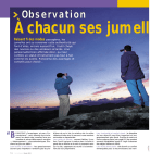
2. Finding the tip-tilt guide star
Find your object with the science instrument. Start Movie in Full FOV mode and look for
a “good” guide star. Move the guide star into the default subarray box by clicking on the
guide star with the right mouse button (this works only when using draw as the default
image display program, so don’t check Use saoimage in the Options menu). The default
subarray is in the upper left corner. This is the optimal position for minimizing the readout
time of the subarray.
If the star cannot be moved into that box, define a new subarray by clicking on the star
with the left mouse button. Now, typing q inside the image window automatically invokes
the Custom subarray mode in astroCam.tcl. The Custom subarray width can be
adjusted by moving the slider. Using Movie again reads out exactly the newly defined
subarray.
If the default subarray is fine clock on Subarray to define this part of the chip for the next
imaging action.
3. Checking the readout parameters
To achieve a high loop frequency, the shutter of the CCD camera has to stay open and the
camera is operated in a kind of frame transfer mode (see section Imaging modes in chapter
Glossary). As the exposure is slightly different in the shutter modes like Movie and in the
'frame transfer modes' one has to take images with Store Corrected before starting the
final Tip-tilt ON for unlimited correction.
The minimum shutter open time is about 25ms even though a smaller Exposure time was
chosen.
Store Corrected (store a given number of images with tip-tilt correction on) or Store
Focus Corrected (same as Store Corrected plus focus correction) reads out a limited
number of frames that has to be specified in Frames to store. The >> indicates that by
clicking on the text Frames to store a popup menu gives a selection of numbers that can
be chosen. Once Store Corrected is started it cannot be stopped.
Be careful not to choose 1 second exposure time and 4096 frames: that
keeps the system busy for more than an hour. Then, the only cure is
resetting the VxWorks system.
8
The MPIA-UKIRT-Project Software User’s Guide
Document Revision: 1
Chapter 2: Tip-tilt correction
Tip-tilt ON and Tip-tilt + Focus ON
One should aim at using a Loop frequency of at least 50 Hz, and to have an exposure time
of at least the readout time. This can be checked by roughly estimating the cycle time as
the reciprocal of the Loop frequency, and compare it to the Exposure time. At 50-70Hz,
the exposure time is usually larger than the readout time.
As all images are stored when using Store Corrected the images are displayed at the end
of the sequence. The display style is defined by AstroCam. They call it tile image because
the images are displayed like tiles on the wall. Use the mouse to check whether the
number of counts is all right and the stars look nice, i.e. round. As the tip-tilt correction is
on in this mode the star should be spread out equally over the four central pixels. If you
have counts between 2000 and 50000, with the background being set to 1000, things are
fine. If the counts are too high, choosing a lower binning factor reduces the flux per pixel.
At the end of the Store Corrected sequence, two graphs with two curves each pop up. The
first shows the center positions (in CCD pixel units) that should all be around zero, the
second shows the Piezo commanded positions that have to be between -0.0001 and
0.0001. If the latter curve is a straight line at -0.0001 or 0.0001 that means that the
corresponding Piezo has reached the limit of its throw. The star has to be repositioned in
its subarray, by using the middle mouse button in Movie mode. One exits from this display
by moving the mouse into the xterm window that was opened with the graphs and hitting
the return key.
4. Tip-tilt ON and Tip-tilt + Focus ON
One can now guide on that star by clicking on Tip-tilt ON. To select tip-tilt and focus
correction click Tip-tilt + Focus ON. The real-time image center coordinates are
displayed in another salmon colored GUI (auigui.dl) that can be activated either by typing
aui or by clicking on aui in one of the other *.dl windows.
In the Tip-tilt ON mode, the gain can be adjusted on-line, simply by moving the Gain
slider in astroCam.tcl. The effect is quite obvious. A gain of 100 should be fine when the
PZT drives are operated in closed loop mode. Overcritical (gain > 100) and undercritical
(gain < 100) operational modes can improve tip-tilt correction.
5. Tip-tilt correction and chopping
Click on the Enabled/on button below the Chop modes label in the mcugui.dl window.
To select a chop angle and a chop throw move/change the sliders below the Chopping
label. Find and select a star as described above.
You have to (re)select a star as described above after modifying any of the
chop parameters.
Press Tip-tilt ON or Tip-tilt + Focus ON.
Please note that whenever you change the Chopping Angle the Camera angle (check the
becgui.dl window) changes so that a chop throw remains aligned with the orientation of a
CCD (tip-tilt sensor) line.
MPIA Release: 1.0
The MPIA-UKIRT-Project Software User’s Guide
9
Chapter 2: Tip-tilt correction
Snapshots of becgui.dl and mcugui.dl
6. Snapshots of becgui.dl and mcugui.dl
10
The MPIA-UKIRT-Project Software User’s Guide
Document Revision: 1
Chapter 3: Glossary
1. CCD parameters
The region of the CCD that is read out can be defined by Full Frame, Full FOV,
Subarray and Custom subarray. The numbers on the left (X-origin, Y-origin, X-width,
Y-width, Custom subarray width and Binning) give the detailed information. In Full
Frame, Full FOV and Subarray mode, only Binning can be adjusted. In Custom
subarray all parameters can be adjusted manually.
•
•
•
•
Full Frame is the total visible area of the CCD.
Full FOV is the part of the CCD where CHARM produces an image.
Subarray is the default subarray for fastest readout.
Custom subarray can be defined by the user either by typing the coordinates in the
GUI or by using the left mouse button in Acquisition mode.
2. Gain
Gain is the factor (in %) of the measured image center position that is applied to the
Piezos. 100% means that the Piezos attempt to put the measured center position to the
center of the subarray. 80% means that the image center after correction is 20% of the
measured value. Reducing the gain to values smaller than 100% provides some sort of
damping and increasing the gain to values greater than 100% provides overcritical
operation.
MPIA Release: 1.0
The MPIA-UKIRT-Project Software User’s Guide
11
Chapter 3: Glossary
System status and Command status
3. System status and Command status
Both provide information on these statii. Messages are idle and busy, and sending
command, ok, acceptTimeout and commandTimeout.
4. Setup
Refresh CCD starts blinking after 60 minutes. Clicking on that button reinitializes the
CCD. This takes about 20 seconds and removes all the charge that has accumulated in
open shutter modes. It's a good idea to do it from time to time, but by no means vital.
5. Imaging modes
There are Acquisition, Dark, Movie, Tip-tilt ON, Tip-tilt + Focus ON, Store
Corrected, Store Uncorrected, Store Focus Corrected and Store Focus Uncorrected.
• Acquisition takes one image and displays it. In this mode as well as in Movie mode
the shutter is opened and closed, and the middle and the right mouse button can be
used to move the star on the CCD. In addition to these features, one can define a
custom subarray in Acquisition mode by clicking with the left mouse button on the
desired center position of the subarray. Then, the Custom subarry is invoked
automatically after exiting from the Acquisition mode by typing q inside the
image.
• Movie is essentially the same as Acquisition except that it refreshes the image as
fast as it can until typing q with the cursor in the image.
• Dark takes an 'image', but the shutter remains closed. This allows you to check the
background.
• Tip-tilt ON (or Tip-tilt + Focus ON) starts the tip-tilt correction (and Focus
correction) until clicking on
• Stop LOOP. At the end, the last subarray is displayed to make sure that guiding
was done on a star and not on the sky background. If the system starts oscillating
the Gain can be set to smaller values. In the auigui.dl window the centroids are
displayed on-line.
• Store (Focus) Corrected takes a number of images specified in Frames to store
and displays the centroid position as a graph (gnuplot) and, after hitting the return
key with the cursor in the underlying window, the voltages sent to the Piezo as a
graph. Hitting the return key again exits from this graph mode and the image
displaying all the subarrays as a tile image. Here one can check the intensity in the
single images.
• Store (Focus) Uncorrected does the same as above, except it doesn't correct and it
doesn't display the voltages. Here, one can check in the tile image e.g. whether the
star leaves the subarray.
12
The MPIA-UKIRT-Project Software User’s Guide
Document Revision: 1
Chapter 3: Glossary
Other business
6. Other business
The exposure time is set with exposure time. The loop frequency (the reciprocal of the
sum of exposure time and readout time and overhead) is calculated automatically
according to the position and the size of the subarray. Vice versa, one can choose the loop
frequency and the exposure time will be set accordingly. One should always make sure
that the read out time is at least 4-5 times shorter than the exposure time. Changing the
binning changes the readout time and, thus, the loop frequency is adjusted accordingly.
7. Data files
Each Imaging (except Movie, Tip-tilt (+ Focus) ON) command creates a FITS data file
with a filename defined in the Options -> Save ... menu. Each data file consists of a prefix
and a 4 digit number, e.g. /work/tracker/data/Aug96/test0000.
In your working directory ($WROOT) a symbolic link LAST.fits points to the last image
taken.
Movie creates a FITS data file movie.fits in $WROOT.
Tip-tilt (+ Focus) ON creates a FITS data file doTipTilt.fits in $WROOT.
All Store ... (Un)corrected commands create an additional table file ready to plot with
gnuplot, e.g.
gnuplot storeAllCorr.gpl or gnuplot storeAllUncorr.gpl.
The table file name is created by adding .centroid4 to the FITS data file name.
MPIA Release: 1.0
The MPIA-UKIRT-Project Software User’s Guide
13
Chapter 3: Glossary
Snapshot of auigui.dl
8. Snapshot of auigui.dl
14
The MPIA-UKIRT-Project Software User’s Guide
Document Revision: 1
Chapter 4: What to do when ...
1. Questions and answers about using the MPIA-UKIRT-Project
software
How can I reboot the AstroCam camera?
Open the VME/VxWorks console or window and give:
cd "/ASTROMED/42gci" then type
vx42gci("new") and finally type
aui("b016link","setor","2")
How can I log (save to a file) all these Info (verbose mode 1) or Debug (verbose mode 2)
messages when I activate Verbose mode 3 (Info and Debug messages) in one of the *.dl
windows?
Open an xterm window on your workstation. From this xterm window open a telnet
session to the VME/VxWorks system. Hold down the <Ctrl>-key and the left mouse
button and select Log to File from the Main Options menu that pops up.
The AstroCam system does not boot. How can I check the transputer communication?
Type the command inmosCheck on the VME/VxWorks console. If the output doesn’t
look like the one below you probably have a hardware or cabling problem.
Using /bxvi00 inmosCheck 3.0
# Part rate Mb Bt [ Link0 Link1 Link2 Link3 ]
0 T16 -20 1.75 1 [
1:0 HOST
...
... ]
1 T2
-20 1.20 0
[
0:0
...
...
...
]
How can I log (save to a file mcu.log) status information of the mcu subsystem?
Open the VME/VxWorks console and give: mcuSysStatusAll(1) > mcu.log
How can I log (save to a file bec.log) status information of the bec subsystem?
Open the VME/VxWorks console and give: becSysStatusAll(0,1) > bec.log
MPIA Release: 1.0
The MPIA-UKIRT-Project Software User’s Guide
15
Chapter 4: What to do when ...
Questions and answers about using the MPIA-UKIRT-Project software
Is there an easy way to move a star on the Tip-tilt sensor via the crosshead?
Select Full FOV and start Movie in astroCam.tcl. When the image display pops up click
with the middle mouse button on a star, move the pointer to the "new" position inside the
image display and click the middle mouse button again. The star will move the last
"clicked" position.
16
The MPIA-UKIRT-Project Software User’s Guide
Document Revision: 1