1
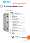
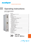
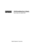
Professional Headend Solutions Operating instructions ASI Transmodulator ASI MPEG RADIO → FM-RADIO Contents 1. Safety and operating instructions.................................................................. 2 2. Device variants .............................................................................................. 2 3. General ........................................................................................................... 2 4. Front view ....................................................................................................... 3 5. Functional description..................................................................................... 3 6. Adjustments ................................................................................................... 3 6.1 Adjustment with the Headend Controller................................................... 3 6.2 Adjustment with the PC/ laptop . ............................................................... 3 7. Meaning of the status LED`s ......................................................................... 4 7.1 LED`s for the ASI ports ............................................................................. 4 7.2 LED`s on front panel ................................................................................. 4 8. Programming by web server . ......................................................................... 5 8.1 Main menu ................................................................................................. 5 8.2 Loading the programme list ...................................................................... 6 8.3 Extended settings . .................................................................................... 7 8.4 Factory settings.......................................................................................... 7 8.5 Configuration of ASI channel 2................................................................... 7 8.6 Configuration of static RDS ....................................................................... 8 8.7 Status of the device ................................................................................... 8 8.8 Software overview ..................................................................................... 9 9. Manual menu control at the Headend Controller ........................................ 10 10. Trap messages ............................................................................................. 11 11. Block diagram .............................................................................................. 11 12. Head end bus structure................................................................................ 12 13. Application example...................................................................................... 12 14. Technical data .............................................................................................. 13 15. Bibliography ................................................................................................. 13 16. Glossary ....................................................................................................... 14 17. Document history ......................................................................................... 14 ATR 221 Part No: 9860.01 ATR 221 Part N : 9860.01 o ASI Transmodulator ASI MPEG RADIO → FM-RADIO B LINE 1. Safety and operating instructions When assembling, starting-up and adjusting the modules, it is necessary to consider the system specific references in the manual instruction! The modules may only be installed and started up by authorized technical personnel! When assembling the modules into the receiving points, the adherence of the EMC regulations is to be secured! The assembly and wiring have to be done without voltage! All active modules may only be operated with the Headend Controller HCB x00 or Bus Extender BEB x00! The main voltage and the operating voltage of the modules working by DC have to be in complience to the operating parameters described in the technical data. With all work the defaults of the DIN EN 50083 have to be considered! Especially the safetyrelevant execution of the DIN EN 60728-11 [3] is necessary! 2. Device variants ATR 221 9860.01 2 x ASI (TS) → 6 x FM [87,5 ... 108 MHz] Minimum software requirements for HCB x00: 9650.03: version 2.34* 9650.04/.05: version 3.18* 9652.01: version 3.23* * ) updates: www.blankom.de 3. General The ASI transmodulator ATR 221 is a module of the head end system B-LINE, which is conceived as a complete system for middle sized networks. The ATR 221 makes it possible to produce up to 6 radio programmes coded as MPEG2 from two ASI transport streams in the FM range. All the components are programmed via a central control unit and will function independently thereafter. The status of the modules are displayed via LED’s (see chapter 7.2 „LED`s on front panel “). 2 ATR 221 Part N : 9860.01 ASI Transmodulator ASI MPEG RADIO → FM-RADIO o B LINE 4. Front view B LINE managed by SNMP DCS ASI TS input 1 LED input 1 ASI TS input 2/ output LED input 2/ output ASI IN ASI TRANSMODULATOR ASI MPEG RADIO FM RADIO Type: ATR 221 Part No.: 9860.01 ASI/ TS-MODE ASI/ TS-RATE INPUT LEVEL FM OUT OUTPUT LEVEL SUPPLY CURRENT ASI IN/OUT burst,continuous/ 188, 204 270/ 0.65...210Mbps 200...880 mVpp 87.5...108 MHz max. 6 x 110 dBµV 0.75 A ASI TRANSMODULATOR ASI MPEG RADIO FM RADIO Type: ATR 221 Part No.:9860.01 ASI/ TS-MODE burst, continuous/ 188,204 ASI/ TS-RATE 270 /0.65...210 Mbps INPUT LEVEL 200...880 mVpp FM OUT 87.5...108 MHz OUTPUT LEVEL max. 6 x 110 dBµV SUPPLY CURRENT 0.75 A Operating voltage/ control bus X2 X1 STANDBY READY 1 READY 2 ADDR. LED ”STANDBY” (red) LED ”READY1” (green) LED ”READY2” (green) LED ”ADDR.” (yellow) Address selector FM Output coupler ”input” IN OUTPUT LOOP Output coupler ”output” OUT gile 5. Functional description The transport streams (TS) passed on by the input section are processed on entering the system. The SI data are extracted and sent on to the control system so that the services to be decoded can be displayed and selected. At the same time, the audio streams to be decoded are filtered out of the transport streams, as are the RDS data, and these are passed to the DSP. The DSP decodes the MPEG data streams which it receives. The RDS data received from the TS processing stage and are sent on, together with the decoded MPEG data streams, to the FPGA of the modulator. 6 complete FM modulators for VHF are implemented in the FPGA. The audio signals are subjected to 19-kHz filtering in these. Next comes the stereo processing: the audio signals are added or subtracted and are modulated to match the 38-kHz carrier; to the audio signal a 19-kHz pilot tone and the RDS data are added. The MPX signal produced in this way is then modulated by FM. The FM signals are combined and passed through a D/A converter. They are then available either via a directional coupler or, simply, direct at the component output port. Each FM channel produced can be configured individually and independently of the others. 6. Adjustments 6.1 Adjustment with the Headend Controller · · · · Adjustment of the addresses at the Bus Extender BEB x00 and at the modules Activation of the programming mode on each module by selecting the line (BEB x00) and the module position (01... 15) at the Headend Controller(HCB x00) → yellow LED illuminates until the beginning of the parameter adjustment Adjustment of the ATR 221 parameters (see chapter 9) → green LED is switched on After the programming the ATR 221 will be automatically switched into the operating mode → yellow LED flashes shortly/ green LED is switched on 6.2 Adjustment with the PC/ laptop · Prerequisite for the remote programming is an “online-connection” according the IP standard and an ethernet connection at the PC/ laptop · Adjustment of the line/ position addresses at the Bus Extender BEB x00 as well as at the modules · At the Headend Controller HCB x00 input IP address (e.g. 192.168.001.001) · For “direct connection” between a PC and HCB x00 use crossover cable (RJ 45) · For connection over a HUB use a normal straight throught patch cable · Start-up HTML browser and put in IP address as target address · If connected correctly the web interface will be opened on the pc and a blue LED (LINK) at the HCB x00 will be lit up. · All adjustments of the modules are specified on the web interface. The manual instructions of the Headend Controller HCB x00 and the Bus Extender BEB x00 have to be considered! 3 ATR 221 Part N : 9860.01 ASI Transmodulator ASI MPEG RADIO → FM-RADIO o 7. Meaning of the status LED`s 7.1 LED`s for the ASI ports Colour Status Meaning of display green permanently on ASI channel has been configured as input flashing no ASI signal permanently on ASI channel has been configured as output flashing no ASI signal yellow 7.2 LED`s on front panel Designation (Colour) Status Meaning of display STANDBY (red) permanently on Module is in standby flashing Module faulty (hardware) permanently on Module working (ASI input 1), everything ok flashing Error warnings depending on signal: - ASI without sync (e.g. when there is no input signal) - at least one of the adjusted Audio-PID`s can not be decoded permanently on Module working (ASI input 2), everything ok flashing Error warnings depending on signal: - ASI without sync (e.g. when there is no input signal) - at least one of the adjusted Audio-PID`s can not be decoded off ASI channel 2 is configured as output illuminated/ flashing remote control connection/ data being exchanged READY 1 (green) READY 2 (green) ADDR (yellow) 4 B LINE ATR 221 Part N : 9860.01 ASI Transmodulator ASI MPEG RADIO → FM-RADIO o 8. Programming by web server* B LINE 8.1 Main menu Description Module name, editable (max. 30 characters) ASI-Channel Status ASI-Channel 2 displays the ASI channel (1 or 2) currently in use If there is a channel input (there will always be channel 1, and after configuration channel 2), this shows whether there is SYNChronisation or noSYNChronisation at input port. If channel 2 has been configured as output, the message will be “Configures as output”. configuration button for the ASI channel 2 (see menu 5) FM-Channel Channel name displays the settings for the FM output channel(s) (1 to 6) name of programme of the respective FM channel, editable (max. 25 characteres) Program settings Program listing ASI-channel Audio PID loading of the list with available programmes with pre-selection: all programmes or only radio- programmes (see menu 2) selection: 1/ 2 Audio PID of the programme, adjustment range: 0 … 16383 FM-Output RF-Signal Output frequency RF-Level correction Output attenuation RF-Output mode selection: On/ Off adjustment range: 87500 ... 108000 kHz adjustment range: +3 …-3 dB in 0.5-dB steps (per channel) adjustment range: 0 … 31 dB in 1-dB steps (module) selection: loop/ only output * For further details see the HCB manual 5 ATR 221 Part N : 9860.01 o Audio settings Audio mode Audio gain ASI Transmodulator ASI MPEG RADIO → FM-RADIO B LINE selection: Mono/ Mono1/ Mono2/ Stereo/ Auto adjustment range: +6 ... -10 dB in 0.5-dB steps RDS-Settings Data source/ mode selection: RDS-PID/ Audio-PID/ Static/ Off RDS-PID adjustment range: 0 … 16383 Routing to the adjustment menu: configuration static RDS (see menu 6) Operating status SNMP-Trap messages Factory settings selection: On/ Off/ reset selection: On/ Off, if SNMP option in HCB x00 enabled, otherwise „locked“ displays setting the default values (see menu 4) Routing to the respective adjustment menus: Extended settings Status Software versions see menu 3 see menu 7 see menu 8 8.2 Load programme list (menu 2) In this menu, all of the input stream contained services are listed. Depending on the preselection only radio-services or all services appear. For every of the 6 FM channels a service can be choosen. The assumption/settings of the services occurs by pressing the “Transmit” button. 6 ATR 221 Part N : 9860.01 o ASI Transmodulator ASI MPEG RADIO → FM-RADIO B LINE 8.3 Extended settings (menu 3) FM-Channel Preemphasis displays the adjustments of the FM-channels (1...6) selection: 50 µs/ 75 µs/ Off Modulation settings Pilot Signal Pilot deviation correction RDS-Signal RDS-Deviation correction selection: On/ Off adjustment range: +2 ... -2 kHz in 0.1-kHz-steps selection: On/ Off adjustment range: +2 ... -2 kHz in 0.1-kHz-steps 8.4 Factory settings (menu 4) When this menu item is requested, at first a security query whether it really set all parameters to the factory default settings pops up. Affirming the query, all settings stored in the EEPROM will be deleted and re- placed by the default settings. The module will go back to these default values. Once the setting process is over, there will be an automatic return to the main menu. It takes about one minute. 8.5 Configuration of ASI channel 2 (menu 5) In this menu, the ASI channel 2 can be separately configured as an input or as an output to loop throught the ASI input stream. 7 ATR 221 Part N : 9860.01 ASI Transmodulator ASI MPEG RADIO → FM-RADIO o 8.6 Configuration of static RDS (menu 6) FM-Channel Output frequency Audio PID PI-Code PS-Name Radio text PTY-Code EON M/S-Code DI-Code TP-Signal TA-Signal CT-Signal UTC-Time Local Time offset CEST-Correction * displays the settings for the FM output channel(s) (1 to 6) displays the frequencies set for the FM channel (in kHz) shows the audio PID of the selected service adjustment range: 0000 … FFFF (hexadecimally)* 8 characters of the name of the transmitted programme or service max. 64 characters, which can be transmitted statically selection of the programme type selection: On/ Off selection: music/ language decoder identification control code, entered decimally. Default setting: 1 (stereo) selection: On/ Off selection: On/ Off selection: On/ Off displays the UTC time transmitted in the RDS relection + 12 ... - 12 h input of the offset between local and UTC time enable/ disable automatic CEST correction The current list of PI codes for German radio broadcasters can be found on the following website: www.irt.de./de/themengebiete/digitaler-hoerfunk/radio-daten-system-rds.html 8.7 Device status (menu 7) 8 B LINE ATR 221 Part N : 9860.01 o ASI Transmodulator ASI MPEG RADIO → FM-RADIO ASI-Channel Status Data rate Workload TS-ID displays the ASI channel (1 or 2) currently in use synchronization status data rate of ASI channel …payload of this data rate in % displays TS-ID FM-Channel Output frequency Audio status displays the details for the FM output channel(s) (1 to 6) displays in kHz audio status informations dynamically RDS data PI-Code PS-Name Radio text displays the sender‘s PI code as contained in the data stream displays the service name as contained in the data stream displays the radio text as contained in the data stream Information Error memory Temperature Device number Device index displays the errors arising in internal communication between the controllers temperature of the front circuit board displays the device number displays the device index 8.8 Software overview (menu 8) Name of device, item number, address in head end Software versions displays the software versions for the controllers as follows: Controller of the front circuit board Transport stream manager Boot controller of the FM modulator FPGA FM modulator FPGA RDS encoder MPEG decoder Boot controller of the ASI input FPGA ASI input FPGA 9 B LINE ATR 221 Part N : 9860.01 o ASI Transmodulator ASI MPEG RADIO → FM-RADIO 9. Manual menu control at the Headend Controller (HCB x00) ATR 221-start Edit or end Power Status On/ Reset/ Off Description ASI-Channel 2 input/ output RF output RF operation mode Attenuation only output/ loop through 0...31 dB Time settings Time offset CEST correction +12 ... -12 h On/ Off Channel 1...6 or end Programme settings Channel name ASI TS source Audio PID max. 25 characters 1/ 2 0...16383 FM output RF output Output frequency RF level correction On/ Off 87500...108000 kHz +3...-3 dB Audio settings Audio mode mono/ mono1/ mono2/ stereo/ auto Audio amplification +6...-10 dB RDS settings RDS mode/ source RDS PID RDS PI Code RDS PS Name RDS PTY Code RDS TP Signal RDS TA Signal RDS M/S Signal RDS DI Code RDS EON RDS CT Signal RDS PID/ Audio PID/ Static/ Off 0...16383 0x0000...0xFFFF (8 characters) (selection) On/ Off On/ Off music/ speech On/ Off On/ Off Settings Preemphasis/ Modulation Preemphasis Pilot signal Pilot deviation correction RDS signal RDS deviation correction 50 µs/ 75 µs/ Off On/ Off +2...-2 kHz On/ Off +2...-2 kHz ATR 221-end 10 B LINE ATR 221 Part N : 9860.01 ASI Transmodulator B ASI MPEG RADIO → FM-RADIO o 10. Trap messages Item Message Type Explanation 01 Signal OK INFORMATION Module works correctly. 02 Input not sync WARNING Input is not synchronized. 03 MPEG: Open Error CRITICAL Access error MPEG decoder 04 System reset WARNING Reset after internal error 05 MPEG-Decoder not sync WARNING MPEG decoder is not synchronized. 06 Power fail CRITICAL Error on supply voltage 07 MPEG-Decoder sync INFORMATION MPEG decoder is synchronized. 08 ATMEGA: Open Error CRITICAL Access error FM boot controller 09 NIOS: Open Error CRITICAL Access error RDS encoder 11. Block diagram ASI-Frontend ASI IN ASI IN oder OUT TS1 TS2 Processing Supply Control SI-Processing Control DSP 6 x MPEG Decoder 6 x FM Modulator RDS Controller FPGA RF RF IN D RF OUT A 11 LINE ATR 221 Part N : 9860.01 ASI Transmodulator ASI MPEG RADIO → FM-RADIO o Module ADDR. 15 Module ADDR. 15 Module ADDR. 15 Module ADDR. 01 Module ADDR. 01 BEB x00 ADDR. 01 Module ADDR. 01 Modul signal processing unit BEB x00 ADDR. 02 BEB x00 Bus Extender BEB x00 ADDR. 15 HCB x00 Headend Controller HCB x00 12. Head end bus structure The number of the possible module connections (00 ... 15) to a BEB x00 depends on the total power consumption of this line! 13. Application example 12 B LINE ATR 221 Part N : 9860.01 o ASI Transmodulator B ASI MPEG RADIO → FM-RADIO LINE 14. Technical data ASI input Level range Data rate Connector Impedance ASI polarity 200 … 880 mVpp 270 Mbps BNC socket 75 Ω regular/ inverted ASI output Level Data rate Connector Impedance ASI polarity 800 mVpp (± 10 %) 270 Mbps BNC socket 75 Ω normal ASI signal processing Data rate ASI transfer format Input Output TS transfer format Input Output Signal processing 0.625…78 Mbps continuous, burst burst 188, 204 Byte 188, 204 Byte EN 50083-9 [1] FM modulator/ FM output Max. FM deviation 75 kHz LF level range (deviation correction) -10 … +6 dB Frequency range 87.5 … 108 MHz Frequency step 50 kHz Output impendance 75 Ω Output return loss > 16 dB Amplitude response 40 Hz...15 kHz, reference 400 Hz, preemph. 50 µs < ± 0.5 dB Rejection of modulation frequencies between 18.9…19.1 kHz and 23…100 kHz > 40 dB Total harmonic distortion between 40 Hz…15 kHz bei 40 kHz Hub > 66 dB at 400 Hz 40 Hz…15 kHz bei 75 kHz Hub > 60 dB at 400 Hz Difference-tone-attenuation D2 between 40 Hz…15 kHz > 70 dB SNR weighted (pre- and deemphase 50 μs, R, L) > 66 dB (Quasi-Peak- Detector, CCIR weighted) SNR unweighted (pre- and deemphase 50 μs, R, L) > 72 dB (Quasi-Peak- Detector, CCIR unweighted) Cross-talk attenuation in range 40 Hz…100 Hz > 38 dB (- 26 dBFS) 100 Hz…15 kHz > 40 dB (- 26 dBFS) Output frequency inaccuracy after 24 hours on 25 °C Temperature depended frequency inaccuracy Spurios between 47…87.5 MHz and 111…862 MHz 87.5…111 MHz Frequency error Output level (switchable) direct output (w/o direct. coupler) with directional coupler Total level Individual level Connector Stereo coder Processing Deviation pilot RDS coder Processing Deviation Supported services Operating parameters Current/ voltage Residual ripple of supply voltage Enviromental conditions Temperature range Temperature range for data keeping Relative humidity Method of mounting Location of mounting < ± 2 kHz < ± 2 kHz ≥ 64 dB ≥ 60 dB ≤ 3 kHz max. 6 x 110 dBµV max. 6 x 100 dBµV 1 dB (0 … 31 dB) 0.5 dB (± 3 dB) F socket Multiplex, CCIR 6.7 kHz EN 62106:2001 [2] 2.4 kHz PS, PTY, TP, TA, EON, PI, RT, MS, CT, DI 12 V (± 0.2 V)/ 750 mA ≤ 10 mVpp -10 ... +55 °C 5 ... 45 °C ≤ 80 % (non condensing) vertical splash-proof and drip-proof Miscellaneous Dimensions (l x w x h) without 19” adapter 50 x 276 x 148 mm with 19” adapter 50 x 301 x 148 mm Weight 1,200 g Delivery content 1 x Bus connector 1 x F connecting cable 140 mm 15. Bibliography [1] EN 50083-9: Cabled distribution systems for television, sound and interactive multimedia signals, part 9: Interfaces for CATV/ SMATV head ends and similar professional equipment for DVB/MPEG-2 transport streams [2] EN 62106:2001 : Specification of the radio data system (RDS) for VHF/ FM sound broadcasting in the frequency range from 87.5 to 108.0 MHz (IEC 62106:2000); German version [3] EN 60728-11: Cable network for television signals, sound signals and interactive services Part 11: safety (IEC 607278-11: 2005). German version EN 60728-11: 2005 [4] RFC 1157 Request for Comments (RFC): RFC Database; url: http://www.rfc-editor.org/rfc.html 13 ATR 221 Part N : 9860.01 ASI Transmodulator B ASI MPEG RADIO → FM-RADIO o LINE 16. Glossary AM AP ASI ATV AV CCIR CEST CT C/N D/A DI DSP DVB EON ETSI FIFO FM FPGA HTTP ID IF IIC IP LED MC MIB MPEG MS NIM PCR PI PID PLL PMT PS PTY RDS RF RT SNMP SPI SPTS TA TP TS UTC Amplitude modulation Anschlussplatte (front circuit board) Asynchronus Serial Interface Analog Television Audio/ Video Comité Consultatif International Radiocommunication Central European Summer Time Clock Time Carrier to Noise ratio Digital/ Analog Decoder-Identification-Control code Digital Signal Prozessor Digital Video Broadcasting (-C Cable, -S Satellite, -S2 Satellite 2, -T Terrestial) Enhanced Other Network European Telecommunications Standards Institute First In–First Out Frequency modulation Field Programmable Gate Array Hypertext Transfer Protocol Identifier Intermediate Frequency Inter-Integrated Circuit (I²C bus, data bus within device) Internet Protocol Light Emitting Diode Microcontroller Management Information Base Moving Picture Experts Group Music/ Speech Network Interface Module Program Clock Reference Programm Identification Program Identifier Phase Locked Loop Program Map Table Program Service Name Program Type Radio Data System Radio Frequency Radio Text Single Network Management Protocol Serial Peripheral Interface Single Program Transport Stream Traffic Announcement Traffic Program Transport Stream Universal Time Coordinated 17. History Version Date Modification Author 1.00 28.10.2008 Basic document Häußer, Poch 1.01 24.11.2009 Revision Häußer Options available upon request! Subjects to changes due to technical progress. BLANKOM Antennentechnik GmbH Hermann-Petersilge-Straße 1 • 07422 Bad Blankenburg • Germany • Telefon +49 (0) 3 67 41 / 60-0 • Fax +49 (0) 3 67 41 / 60-100 14 Declaration of Conformity The Manufacturer BLANKOM Antennentechnik GmbH ∙ Hermann-Petersilge-Str. 1 ∙ 07422 Bad Blankenburg ∙ Germany herewith declares the conformity of the product Product name: ASI Transmodulator Type: ATR 221 Product number: 9860.01 according to the following regulations EN 50083-2 EN 60728-11 (as far as relevant) and additional device-specific regulations, enclosed above, which this product is subjected to. Date: 03.11.2009 Signature: (Managing Director) 15