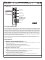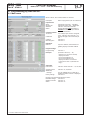
1
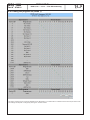
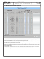
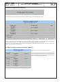
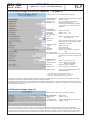
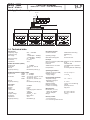
Professional Headend Solutions Operating instructions TWIN SAT-Streamer DVB-S/-S2 → 2 x CI → IP & ASI monitoring Contents 1. Safety and operating instructions.................................................................... 2 2. Device variants ................................................................................................. 2 3. General ............................................................................................................. 2 4. Front view ......................................................................................................... 3 5. Functional description....................................................................................... 3 6. Adjustments ..................................................................................................... 3 6.1 Adjustment with the Headend Controller................................................... 3 6.2 Adjustment with the PC/ laptop.................................................................. 3 6.3 Adjustment with SNMP............................................................................... 4 7. Meaning of the LED‘s ....................................................................................... 4 7.1 LED‘s at the stream port . .......................................................................... 4 7.2 Status LED‘s .............................................................................................. 4 8. Programming by web server . .......................................................................... 5 8.1 Main menu . ............................................................................................. 5 8.2 Loading the program list ........................................................................... 6 8.3 CA menu ........................................................................................................ 7 8.4 Multi-decryption menu................................................................................ 7 8.5 Multi-decryption selection.......................................................................... 8 8.6 Multi-decryption test................................................................................... 9 8.7 Multi-decryption test information................................................................ 9 8.8 Extended settings of the stream channels 1...16 .................................... 10 8.9 Extended settings . .................................................................................. 10 8.10 Factory settings...................................................................................... 11 8.11 Status of the device ............................................................................... 11 8.12 Software overview ................................................................................. 12 9. Manual menu control at the Headend Controller .......................................... 13 10. Trap messages ............................................................................................. 13 11. Block diagram . ........................................................................................... 14 12. Head end bus structure................................................................................ 14 13. Application example...................................................................................... 15 14. Technical data .............................................................................................. 15 15. Glossary ....................................................................................................... 16 16. Bibliography ................................................................................................. 17 17. Document history ......................................................................................... 17 SSI 108 Part No: 9740.01 SSI 108 Part N : 9740.01 TWIN SAT-Streamer B DVB-S/-S2 → 2 x CI → IP & ASI monitoring o LINE 1. Safety and operating instructions When assembling, starting-up and adjusting the modules, it is necessary to consider the system specific references in the manual instruction! The modules may only be installed and started up by authorized technical personnel! When assembling the modules into the receiving points, the adherence of the EMC regulations is to be secured! The assembly and wiring have to be done without voltage! All active modules may only be operated with the Headend Controller HCB x00 or Bus Extender BEB x00! The main voltage and the operating voltage of the modules working by DC have to be in complience to the operating parameters described in the technical data. With all work the defaults of the DIN EN 50083 have to be considered! Especially the safetyrelevant execution of the DIN EN 60728-11 [6] is necessary! WEEE reg. no: DE 50389067 2. Device variants SSI 108 9740.01 DVB-S/-S2 → 2 x CI → IP & ASI monitoring Minimum software requirements for HCB x00: 9650.03: version 2.34* 9650.04/.05: version 3.25* 9652.01: version 3.25* 9653.01: version 3.27* *) Updates: www.blankom.de 3. General The TWIN SAT Streamer SSI 108 is a module of the head end system B-LINE, which is conceived as a complete system for middle sized networks. The SSI 108 demodulates DVB-S/-S2 signals (8PSK, QPSK) into 2 transport streams, which are sended out over IP. A Common Interface slot enables the use of CA-Modules for the reception of scrambled SAT signals/ programs. Additionally the processed transport streams with the descrambled services are available on the ASI output, and the max. 16 IP transport streams too. All the components are programmed via a central control unit and will function independently thereafter. The status of the modules are displayed via LED’s (see chapter 7.2 “Status LED‘s “). 2 SSI 108 Part N : 9740.01 TWIN SAT-Streamer DVB-S/-S2 → 2 x CI → IP & ASI monitoring o B LINE 4. Front view SAT-IF input coupler “Input“ TWIN SAT-STREAMER DVB-S/-S2 (QPSK/8PSK) CI IP & ASI Type: SSI 108 Part No.: 9740.01 SAT-IF IN 950...2150 MHz INPUT LEVEL 53...93 dBµV STREAM PORT 100/1000 Base-T STREAM PROTOCOL UDP, RTP ASI/TS-MODE burst/188 SUPPLY CURRENT 1.0 A TWIN SAT - STREAMER DVB-S/-S2 (QPSK/8PSK) CI IP & ASI Type: SSI 108 Part No.: 9740.01 SAT-IF IN INPUT LEVEL STREAM PORT STREAM PROTOCOL ASI/ TS-MODE SUPPLY CURRENT SAT-IF input coupler “Output“ 950...2150 MHz 53...93 dBµV 100/ 1000 Base-T UDP, RTP burst/ 188 A 1.0 Operating voltage/ control bus COMMON INTERFACE LED “STANDBY“ (red) LED “READY 1“ (green) LED “READY 2“ (green) LED “ADDR.“ (yellow) Address selector PIN 1 ASI OUT STREAM PORT ASI-TS output Stream port LAN/WAN 5. Functional description The SAT-IF input signal is fed to the DVB-S/ -S2 front end, where the selection of a transponder and its QPSK or 8PSK demodulation are done. The data stream is routed by a switching matrix either to the Common Interface or directly to the IP module. A respective CA module with smart card, which is supported by the device, has to be used for descrambling.* Multi service decryption is possible if there are not any restrictions by the CAM itself or by the service provider. The decryption of MPEG-4 services is supported. With this module its possible to choose elementary streams of a service for decryption. So the ressources of the respective CAM/ smart card combination can be used optimally. The SI and PSI tables affected (i.e. the PAT, PMT, SDT, EIT) are automatically corrected. 16 of all programs contained in both transport streams can be selected and transmitted via IP. This is supported by different protocols. Address and port selection are not restricted, but should be orientated itselfs according recommendations of IANA. The module alows the output of one single program transport stream (SPTS) per IP connection, but also the output of one of both multi program transport streams (MPTS), that can be decrypted. For monitoring there is an ASI output to check one of the 16 stream channels. A permanent 12 V voltage for LNC supply is available at the SAT inputs. * The design of the Common interface of this module is done according to DVB standards. Because of the dependencies in interaction of the DVB signals, CA modules and smart cards we can not assure a general functional capability for all application possibilities. Please contact our service department for further assistance! 6. Adjustments 6.1 Adjustment with the Headend Controller · Adjustment of the addresses at the Bus Extender BEB x00 and at the modules ·Activation of the programming mode on each module by selecting the line (BEB x00) and the module position (01... 15) at the Headend Controller (HCB x00) → yellow LED illuminates until the beginning of the parameter adjustment ·Adjustment of the SSI 108 parameters (see chapter 9) → green LED is switched on ·After the programming the SSI 108 will be automatically switched into the operating mode → yellow LED flashes shortly/ green LED is switched on 6.2 Adjustment with the PC/ laptop ·Prerequisite for the remote programming is an “online-connection” according the IP standard and an ethernet connection at the PC/ laptop ·Adjustment of the line/ position addresses at the Bus Extender BEB x00 as well as at the modules ·At the Headend Controller HCB x00 input IP address (default: 192.168.2.80) ·For “direct connection” between a PC and HCB x00 use crossover cable (RJ 45) ·For connection over a HUB use a normal straight throught patch cable ·Start-up HTML browser and put in IP address as target address ·If connected correctly the web interface will be opened on the pc and a blue LED (LINK) at the HCB x00 will be lit up. ·All adjustments of the modules are specified on the web interface. The manual instructions of the Headend Controller HCB x00 and the Bus Extender BEB x00 have to be considered! 3 SSI 108 Part N : 9740.01 TWIN SAT-Streamer DVB-S/-S2 → 2 x CI → IP & ASI monitoring o B 6.3 Adjustment with SNMP · · · · · Prerequisite for the SNMP functionality is the use of HCB x00 with enabled SNMP software option CKB 100. Supported is SNMP version 1.0 [7]. Automatic creation of the MIB based on the current head end configuration by the HCB x00. Software is required for setting and reading out the parameters and to receive traps from an SNMP management. Further Notes on the SNMP functionality of BLANKOM modules are listed in the SNMP manual. 7. Meaning of the LED‘s 7.1 LED‘s at the stream port Meaning (Colour) Status Meaning of display GbE connect LED (green) permanently on cable connection with GbE off no cable connection with GbE Data LED (yellow) permanently on port active flashing data being exchanged Designation (Colour) Status Meaning of display STANDBY (red) permanently on module is in standby flashing module faulty (hardware error) permanently on module working properly flashing error warnings, depending on signal: - tuner 1/ 2 not synchronized (e.g. there is no input signal) - error of decryption - stream channel to the receiver is broken illuminated/ flashing remote control connection/ data being exchanged 7.2 Status LED‘s READY 1/ 2 (green) ADDR. (yellow) 4 LINE SSI 108 Part N : 9740.01 o TWIN SAT-Streamer DVB-S/-S2 → 2 x CI → IP & ASI monitoring B LINE 8. Programming by web server* 8.1 Main menu Name of device, item number, address in head end Description Input channel SAT-IF Symbol rate Standard Status Common Interface TS-Source CA-Module CA-Menu Multidecryption IP-Network Ethernet Name of programme (max. 30 characters) adjustment range: 950 ... 2150 MHz adjustment range: 1000 ... 45000 kSps selection: Auto, DVB-S, DVB-S2 displays whether SYNChronization or noSYNChronization with input and the format of transmission slot 1 always input channel 1 assigned, slot 2 - selection: input channel 1 or 2 displays the type of the CA module per slot see menu 2 see menu 3 input of IP address, subnet mask and gateway, display of the MAC address Program settings Program listing see menu 1 IP-Output per stream channel (1 ... 16) : - selection: On/ Off (of the channel) - displays the name - input of the destination IP - input of the destination port - displays the status of connection - routing to the menu 7 (extended set- tings) ASI-Output Data source selection: stream channel 1... 16, TS1,TS2 Operating status SNMP-Trap message Factory settings selection: On, Off, Reset On/ Off, if SNMP option in HCB x00 is enabled, otherwise “locked“ is displayed see menu 9 Routing to the appropriate adjustment menu: Extended settings see menu 8 Software overview see menu 11 Status see menu 10 * For further details see the HCB manual 5 SSI 108 Part N : 9740.01 o TWIN SAT-Streamer DVB-S/-S2 → 2 x CI → IP & ASI monitoring B LINE 8.2 Loading the program list (menu 1) This menu contains a list of all services available in the data stream. In the matrix there is a selection of the services per stream channel. Settings are adopted or changed by clicking the “Transmit” button. 6 SSI 108 Part N : 9740.01 o TWIN SAT-Streamer DVB-S/-S2 → 2 x CI → IP & ASI monitoring B LINE 8.3 CA menu (menu 2) Name of device, item number, address in head end On these pages all menus implemented in the CA module are offered. The available menus are selected individually or are invoked one-by-one to do necessary settings or to get all informations about the CA module. 8.4 Multi-decryption menu (menu 3) When calling this menu the selection of the services of the adjusted transponder, which were selected for decryption and whose decryption was successfully, appears. Indicated are the program name with the number of the decoded PID‘s, the decryption settings and the status of the program. “Stored“ means, that the service was successfull decrypted and saved in the CA-service-list. Using the check box “Clear entries“ and the ”Transmit/ Back“ button the entire selection will be deleted and no services are decrypted afterwards. By using the “Selection“ button and the appropriate selection of the services in the multi-decryption selection menu (menu 4) the list of the services to decrypt can be changed. Using the “Testing selection“ button calls the test menu (menu 5), in which the decryption state of all programs in the CA-service-list will be tested again and possible occurring errors will be listed. 7 SSI 108 Part N : 9740.01 o TWIN SAT-Streamer DVB-S/-S2 → 2 x CI → IP & ASI monitoring B LINE 8.5 Multi-decryption selection (menu 4) In this menu all services of the adjusted transponder and their CA status are listed. The services are selectable for decryption. For each of this selected services one can determine, what streams or PID‘s are to be decrypted. That‘s important because the maximum number of the decryptable PID‘s is limited and this limit has a different size per CA module. In the selection boxes “MPEG 1/ 2 Audio Streams“ respective “Subtitling Streams“ all, no or individual streams are selectable. If one wants to select more than one stream, but not all , the selection field ”all“ in the box is to be selected and in the column “PID-Drop list“ all PID‘s have to be entered, that shall not be decrypted.* In the column “PID-Drop list“ all PID‘s are listed, that shall not be decrypted. The PID‘s can be given in decimal or hexadecimal format and have to be separated by a semicolon. The maximum number of PID‘s is 10.** Individual CA modules have to be initialized once again before the CA services will be sent to the module. To do so the option “Reset CA-Modul“ can be activated. “Other Audio Streams“ includes all AC3-, DTS- and AAC-Streams. „Private Streams“ selects all streams which are not captured by the other selection fields. ** Particularly Pid‘s can be given here, which are active only at times and no authorisation for decryption is available for them. * 8 SSI 108 Part N : 9740.01 o TWIN SAT-Streamer DVB-S/-S2 → 2 x CI → IP & ASI monitoring B LINE 8.6 Multi-decryption test (menu 5) First all services, which are saved in the CA-service-list, will be tested for the current decryption status. After the end of the test the multi-decryption menu (menu 3) appears, where in the “Status“-column the test result of the respective service is stated by using the “Info“ button, the relevant information page of the test (menu 6) is displayed. By clicking of the “Transmit/ Back“ button all settings are transmitted. The “Selection“ button routes back to menu 4 to correct input values, e.g. too much PID‘s were selected. 8.7 Multi-decryption test information (menu 6) Name of device, item number, address in head end On this page informations about the test result of the selected service are displayed. First the final result of the test with service ID and CA information is listed, than for each requested PID the type, the CA information and the test result. 9 SSI 108 Part N : 9740.01 o TWIN SAT-Streamer DVB-S/-S2 → 2 x CI → IP & ASI monitoring B LINE 8.8 Extended settings of the stream channels 1 ... 16 (menu 7) Name of device, item number, address in head end Stream channel x Operating status Destination IP Destination Port displays the channel, that will be adjusted selection: On/ Off input of the destination IP number input of the destination port In selecting the destination port please note a distance of 5, if FEC modes were activated. configuration Transmit protocol selection: RTP, UDP FEC-Mode L selection: Off, 1 ... 20 FEC-Mode D selection: Off, 4 ... 20 Set stream data rate to selection: User defined, TS-Data rate, Service data rate User defined data rate input of the data rate in kbps (only if “Set stream data rate to user defined“, adjust- ment range: 0..65535) Change TS-Identification selection: On/ Off TS-ID input of the TS-ID** Network-ID input of the network ID** EIT-Mode selection: EIT completly*, present/ follo- wing Use configuration for all stream channels if box is clicked, all configuration settings are adopted for the other 15 stream chan- nels Service settings TS-Source selection: input channel 1 or 2 Streaming Mode selection: SPTS (one program), MPTS (all programs) Service ID adjustment range: 0..65535*** Program name service name (max. 30 characters) Stream channel * ** *** routing to the next stream channel, that should be adjusted only selectable if “Change TS-Identification Off“ input only if “Change TS-Identfication On“ is selected input only if “Streaming mode SPTS“ is selected The manual configuration of service settings is necessary only if the requested service is not available in the program list. Normally all settings of the service are adopted when the service is selected in the list. The selection “Service data rate“ of the stream data rate is creating a VBR data stream. This mode should be selected only for appropriate target devices, because it will affect PCR accuracy. If there are doubts about it, selection of “TS data rate“ or “User defined“ data rate is strongly recommended. 8.9 Extended settings (menu 8) Name of device, item number, address in head end CA-Configuration SDT/PMT-Proc. Mode CA-PMT-Update Use of Date & Time datas per slot selection: On/ Off selection: CA-PMT-Entry, CA-PMT-Listing selection: On/ Off Some CA modules request ressource “Date & Time“ while being initialised. Otherwise this setting should remain deactivated. The smart card activation mode should only be turned on when a new smart card will be enabled or an expired smart card will be reactivated. Thus, the monitoring functions, necessary for the proper operation of the device, will be disabled in order to ensure troublefree data exchange to enable the card. Depending on the provider, this process may take some time. It should be noted that in this 10 SSI 108 Part N : 9740.01 o TWIN SAT-Streamer DVB-S/-S2 → 2 x CI → IP & ASI monitoring B LINE mode only one service per module is decrypted, the multi-decryption functionality is thus suspended. It is to select this service for decrypting, which includes the activation data (determined by the provider). After successful activation of the card the mode is to disable it in order to ensure the readiness for operating of the device in its entirety (especially the multi-decryption functionality). 8.10 Factory settings (menu 9) When this menu item is requested, at first a security query whether it really set all parameters to the factory default settings pops up. Affirming the query, all settings stored in the EEPROM will be deleted and replaced by the default settings. The module will go back to these default values. In particular all network settings (IP address, subnet mask, gateway and destination IP per channel) are set on address 0.0.0.0 . Once the setting process is over, there will be an automatic return to the main menu. It takes about one minute. 8.11 Status of the device (menu 10) Name of device, item number, address in head end Input channel Status Set values RF-Input level BER/ PER displays datas for channel 1 and 2 displays whether SYNChronization or noSYNChronization with input and the format of transmission displays adjusted SAT IF and symbol rate displays in dBµV bit error rate (DVB-S)/ packet error rate (DVB-S2) Common Interface displays per slot Decoder status displays available messages IP-Output displays status and data rate per stream channel An error indicator in the “Status“ column has generally indicate a too low data rate choosen. Data rate Stream-Port (receive) The value indicates the network load on the IP port that the CPU has to process. Lie permanently on more than 64 Kbps, a review of the network is recommended. Data rate Stream-Port (sent) displays output data rate Information System status Temperature Temperature internally Device number Device index 11 displays available messages displays external temperature of the device displays internal temperature of the de- vice display of the device number display of the device index (hardware) SSI 108 Part N : 9740.01 o TWIN SAT-Streamer DVB-S/-S2 → 2 x CI → IP & ASI monitoring B LINE 8.12 Software overview (menu 11) Name of device, item number, address in head end Software versions Displays the software versions for the controllers as follows: - Controller of terminals board - Controller DVB-S/ S2 frontend 1 - Controller DVB-S/ S2 frontend 2 - CA-Bootcontroller - FPGA CA-Controller - TS-CA-Manager - IP-Bootcontroller - FPGA IP-Controller - IP-CPU - TS-CPU 12 SSI 108 Part N : 9740.01 B TWIN SAT-Streamer DVB-S/-S2 → 2 x CI → IP & ASI monitoring o LINE 9. Manual menu control at the Headend Controller (HCB x00) The values in the blocks settings are the default values. After pushing the button “default“ settings on the main page, all settings stored in the EEPROM are erased and reset to default values. The device is set to these values again (see also chapter 8.10). SSI 108 start Edit or end Power Status On Channel name xxxx Ethernet settings Ethernet IP address Ethernet subnet mask Ethernet gateway 0.0.0.0 0.0.0.0 0.0.0.0 ASI output Data source ASI TS1 CA2 settings TS source CA2 input channel 2 SAT IF input Tuner/ CA settings skip channel 1 or channel 2 Frequency QPSK symbol rate Standard 1236 MHz 27500 kSps auto Table settings SDT/ PMT processing CA PMT update Channel settings Stream port configuration back On CA PMT entry channel 1 ... channel 16 Operating status Destination IP Destination Port Off 0.0.0.0 0 Configuration/ service settings Transmit protocol FEC-Mode L FEC-Mode D Stream data rate User defined data rate TS source Streaming mode Service ID Service name EIT mode Change TS identifikation TS ID Network ID UDP Off Off TS data rate 0 kbps input channel 1 MPTS (all programmes) 0 empty EIT completly Off 0 0 SSI 108 end 10. Trap messages Item Message Message Type Explanation 01 Input sync INFORMATION input synchronized 02 Input not sync WARNING input not synchronized 03 IIC error CRITICAL IIC bus or hardware error 13 SSI 108 Part N : 9740.01 TWIN SAT-Streamer o Item B DVB-S/-S2 → 2 x CI → IP & ASI monitoring Message Message Type Explanation 04 System reset WARNING reset by internal error 05 Internal controller reset WARNING error when accessing internal controller 06 Power fail CRITICAL power supply error 07 Communication CA-Controller lost WARNING error when accessing CA controller 08 Communication IP-Controller lost WARNING error when accessing IP controller 09 IP-Streamer fail WARNING error in IP streamer 10 IP-Streamer ok INFORMATION IP streamer working properly 11 Decoding of service ... fail WARNING error on descrambling of service... 12 Decoding of service ... ok INFORMATION descrambling of service ... ok LINE 11. Block diagram SAT IF 950... 2150 MHz DVB-S/ -S2 front end 1 IP control CI 1 DVB-S/ -S2 front end 2 TS controller with table processing CI 2 TS 1 16 channels IP-TS transmitter IP (RJ 45) ASI ASI (BNC) TS 2 Power supply & control selection CAM Module ADDR. 15 Module ADDR. 15 Module ADDR. 15 Module ADDR. 01 Module ADDR. 01 Module ADDR. 01 . BEB x00 ADDR. 02 Module signal processing unit BEB x00 ADDR. 15 BEB x00 Bus Extender HCB x00 HCB x00 Headend Controller BEB x00 ADDR. 01 12. Head end bus structure The number of the possible module connections (00 ... 15) to a BEB x00 depends on the total power consumption of this line! 14 SSI 108 Part N : 9740.01 B TWIN SAT-Streamer DVB-S/-S2 → 2 x CI → IP & ASI monitoring o LINE 13. Application example SAT IF IN HCB 200 1 2 1 2 1 2 1 2 DVB-S/S2 DVB-S/S2 DVB-S/S2 DVB-S/S2 DVB-S/S2 DVB-S/S2 DVB-S/S2 DVB-S/S2 IP IP IP IP SSI 108 SSI 108 SSI 108 SSI 108 ..... Application server IPSWITCH IP1 IP2 IP3 IP4 IP5 IP6 IP7 IP8 IP9 IP10 IP11 IP12 IP13 IP14 IP15 IP16 IP17 IP18 IP19 IP20 IP21 IP22 IP23 IP24 SFP SFP SFP SFP Layer3/ IGMP Switch IPSWITCH SFP Layer3/ IGMP Switch IPSWITCH IPSWITCH SFP SFP Layer3/ IGMP Switch Layer3/ IGMP Switch SFP Layer3/ IGMP Switch 14. Technical data SAT IF input Frequency range Frequency step AFC range AGC level range Connector Impedance 950 … 2150 MHz 1 MHz ± 3 MHz (SR < 10 MSps) ± 5 MHz (SR ≥ 10 MSps) 53 … 93 dBμV F socket 75 Ω DVB-S demodulator (QPSK) Symbol rate Code rate Roll-off Signal processing 1 … 45 MSps 1/2, 2/3, 3/4, 5/6, 7/8 35 % EN 300 421 (DVB-S) [1] DVB-S2 demodulator (QPSK, 8PSK) Symbol rate QPSK 5 … 36 MSps 8PSK 5 ... 30 MSps Code rate QPSK 1/4, 1/3, 2/5, 1/2, 3/5, 2/3, 3/4, 4/5, 5/6, 8/9, 9/10 8PSK 3/5, 2/3, 3/4, 5/6, 8/9, 9/10 Roll-off 35 % Signal processing EN 302 307 (DVB-S2) [2] ASI output Data rate Polarity Mode TS data rate TS mode Output voltage Connector Impedance Signal processing 270 Mbps normal burst according symbol rate and coding 188 Bytes 800 mVpp ± 10 % BNC socket 75 Ω EN 50083-9 [3] Decryption interface Common Interface Operating voltage Multi-Service decryption PCMCIA-Slot according EN 50221 [4] 5V 24 services max. IP output Network connection (LAN/ WAN) Ethernet, 10/ 100/ 1000 Base-T Plug connection RJ 45 Protocols UDP, RTP, ARP Additional error correction pro-MPEG Code of practise 3 rev. 2 [8] Encapsulation according ETSI TS 102034 [5] Operating parameters Voltage/ current (w/o CAM) Residual ripple of supply voltage Environmental conditions Temperature range Temperature range for data keeping Relative humidity Method of mounting Location of mounting Miscellaneous Dimensions (l x w x h) without 19”-adapter with 19”-adapter Weight Delivery content 1 x bus connector 2 x F connecting cable 140 mm 15 12 V (± 0.2 V)/ 1 A ≤ 10 mVpp -10 ... +55 °C 5 ... 45 °C ≤ 80 % (non condensing) vertical splash-proof and drip-proof 50 x 276 x 148 mm 50 x 301 x 148 mm 1,350 g SSI 108 Part N : 9740.01 o TWIN SAT-Streamer DVB-S/-S2 → 2 x CI → IP & ASI monitoring B LINE 15. Glossary 8PSK AAC AC3 AP ARP ASI BER CA CAM CATV CI CCIR DTS DVB EIT FEC FPGA GbE HTML HTTP IANA ID IF IIC IP LED MC MIB MPEG MPTS QAM QPSK PAT PCR PER PID PMT PLL RTP SDT SMATV SNMP SPI SPTS TS TV UDP VBR 8 Phase Shift Keying Advanced Audio Coding Adaptive Transform Coder 3 (multi channel audio system of company Dolby) Anschlussplatte (front terminal board) Address Resolution Protocol Asynchronous Serial Interface Bit Error Rate Conditional Access Conditional Access Module Cable Television Common Interface Comité Consultatif International des Radiocommunications Digital Theater Systems (multi channel audio system of company with the same name) Digital Video Broadcasting (-C Cable, -S Satellite, -S2 Satellite 2, -T Terrestrial) Event Information Table Forward Error Correction Field Programmable Gate Array Gigabit-Ethernet Hypertext Markup Language Hypertext Transfer Protocol Internet Assigned Numbers Authority Identifier Intermediate Frequency Inter-Integrated Circuit (I²C-Bus, data bus within device) Internet Protocol Light Emitting Diode Microcontroller Management Information Base Moving Picture Experts Group Multi Program Transport Stream Quadrature Amplitude Modulation Quadrature Phase Shift Keying Program Association Table Program Clock Reference Packet Error Rate Packet Identifier Program Map Table Phase-locked loop Realtime Transport Protocol Service Description Table Satellite Master Antenna Television Simple Network Management Protocol Serial Peripheral Interface Single Program Transport Stream Transport Stream Television User Datagram Protocol variable bit rate 16 SSI 108 Part N : 9740.01 B TWIN SAT-Streamer DVB-S/-S2 → 2 x CI → IP & ASI monitoring o LINE 16. Bibliography [1] EN 300 421: Digital Video Broadcasting (DVB): Framing structure, channel coding and modulation for 11/12 GHz satellite services [2]EN 302 307: Digital Video Broadcasting (DVB): Second generation framing structure, channel coding and modulation systems for Broadcasting, Interactive Services, News Gathering and other broadband satellite applications [3]EN 50083-9: Cabled distribution systems for television, sound and interactive multimedia signals, part 9: Interfaces for CATV/SMATV head ends and similar professional equipment for DVB/MPEG-2 transport streams [4]EN 50221: Common interface specification for conditional access and other digital video broadcasting decoder applicati- ons; German version EN 50221:1997 + Corrigendum:2000 [5]ETSI TS 102034: Digital Video Broadcasting (DVB); Transport of MPEG-2 TS Based DVB Services over IP Based Networks, Ver. 1.4.1, 2009-08-04 [6]EN 60728-11: Cable networks for television signals, sound signals and interactive services Part 11: Safety (IEC 60728-11:2005); German version EN 60728-11:2005 [7]RFC 1157 Request for Comments (RFC): RFC Database URL: http://www.rfc-editor.org/rfc.html [8]ETSI TS 102034: Digital Video Broadcasting (DVB); Transport of MPEG-2 TS Based DVB Services over IP Based Networks, Ver. 1.4.1, 2009-08-04 17. Document history Version Date Modification Author 1.00 03.11.2009 Basic document Häußer 1.01 01.02.2010 Revision Häußer 1.02 30.04.2010 Revision/adaptation Häußer 1.03 08.10.2010 Revision chapter 8.8 & 8.9 Häußer 1.04 30.09.2001 Revision chapter 8.11 Häußer 1.05 29.06.2012 Revision chapter 8.9 Häußer Options available upon request! Subjects to changes due to technical progress. BLANKOM Antennentechnik GmbH Hermann-Petersilge-Straße 1 • 07422 Bad Blankenburg • Germany • Phone +49 (0) 3 67 41 / 60-0 • Fax +49 (0) 3 67 41 / 60-100 17 Declaration of Conformity The Manufacturer BLANKOM Antennentechnik GmbH ∙ Hermann-Petersilge-Str. 1 ∙ 07422 Bad Blankenburg ∙ Germany herewith declares the conformity of the product Product name: TWIN SAT-Streamer Type: SSI 108 Product number: 9740.01 according to the following regulations EN 50083-2 EN 60728-11 (as far as relevant) and additional device-specific regulations, enclosed above, which this product is subjected to. Date: 03.11.2009 Signature: (Managing Director) 18