1
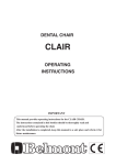
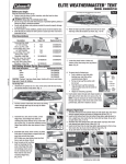
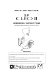
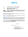
DENTAL UNIT AND CHAIR
OPERATING INSTRUCTIONS
IMPORTANT
This manual provides operating instruction for BELMONT RAPPORT.
The instructions contained in this booklet should be thoroughly read and
understood before operating of the system.
File this manual and refer back to it for future maintenance.
R
0197
TABLE OF CONTENTS
Page
1. OVERALL VIEW AND MAJOR PARTS----------------------------------------------------------- 1
1-1. TABLE UNIT AND DOCTOR UNIT SECTION------------------------------------------------ 1
1-2. ASSISTANT UNIT AND DENTAL LIGHT SECTION---------------------------------------- 2
1-3. CHAIR SECTION----------------------------------------------------------------------------------- 3
2. DIMENSIONS
2-1. CHAIR DIMENSIONS------------------------------------------------------------------------------ 4
2-2. TABLE UNIT DIMENSIONS---------------------------------------------------------------------- 4
2-4. POLE MOUNT LIGHT DIMENSIONS --------------------------------------------------------- 5
2-3. ASSISTANT UNIT DIMENSIONS--------------------------------------------------------------- 5
3. LAYOUT AND SPECIFICATIONS
3-1. LAYOUT---------------------------------------------------------------------------------------------- 6
3-2. SPECIFICATIONS----------------------------------------------------------------------------------- 6
4. OPERATION INSTRUCTIONS
4-1. MASTER SWITCH AND CHAIR MAIN SWITCH-------------------------------------------- 7
4-2. CONTROL PANELS-------------------------------------------------------------------------------- 7
4-3. CHAIR POSITIONS AND CHAIR OPERATING INSTRUCTIONS------------------------ 8
4-4. UNIT OPERATING INSTRUCTIONS---------------------------------------------------------- 11
4-5. SUPPORT FUNCTIONS--------------------------------------------------------------------------- 14
4-6. CEILING LIGHT OPERATING INSTRUCTIONS-------------------------------------------- 17
5. ADJUSTMENTS
5-1. CHAIR AUTO MODE POSITION ADJUSTMENTS----------------------------------------- 18
5-2. HANDPIECE HOLDER FUNCTION CANCELLATION AND RESET------------------- 18
6. CARE AND MAINTENANCE
6-1. CARE AND MAINTENANCE FOR CHAIR--------------------------------------------------- 19
6-2. CARE AND MAINTENANCE FOR UNIT----------------------------------------------------- 19
6-3. CARE AND MAINTENANCE FOR POLE MOUNT LIGHT ------------------------------ 21
7. ELECTROMAGNETIC COMPATIBILITY(EMC) -------------------------------------------- 22
8. LIST OF COMPATIBLE HANDPIECES --------------------------------------------------------- 25 Intended Use of the Product
This product is an active therapeutic device intended for the exclusive use for diagnoses,
treatments and relative procedures of dentistry.
The product must be operated or handled by the qualified dentists or by dental staffs under
the supervision of the dentist.
Such dentists or dental staffs should instruct and/or assist the patients to approach to and
leave from the product.
Patients should not be allowed to operate or handle the product unless he/she is so instructed.
The product is supplied together with the handpieces like electric micromotor, air turbine
and/or motor, scaler and so on.
Environmental Requirements
Ambient Temperature
Operating +5℃ - +40℃
Humidity 10 % - 80%
Storage -10℃ - +50℃
Atmospherical Pressure 600 hPa - 1060 hPa
Compatibility of Handpieces
Use the compatible handpieces as shown on the attached list for this unit. (List of compatible
handpieces).
Important Notes
In case of the troubles, please contat Takara Belmont offices or your dealers.
Do not disassemble or attempt to repair.
Disassembly, repair or modifications shoud only be done by a qualified repair technician.
Attempts at disassembly, repair or modifications may lead to abnormal operation and accidents.
In case of disposal of equipment
In case of disposal of equipment or of components dismounted from the unit, take full infection preventing measures, and carry out appropriate steps in accordance with the legal regulations
at that time.
SYMBOLS
)2
㹌
Chair preset1
Chair
auto control
Chair
auto control
To raise the chair
To lower the chair
To Recline
the backrest
To raise
the backrest
Treatment position
Consultation position
Toothbrushing
position
Handpiece Setting
Fiber optic
handpiece light
on//off
Micro motor
otation mode
select
Micro motor
Forward/Reverse
select
Handpiece water
flow control
Handpiece memory
Fiber optic
handpiece light
on//off
Handpiece coolant
water on/off
Handpiece coolant
air on/off
Micro motor
speed control
Dental light on/off
Flush out
Syringe
Function
Store
Bowl flush
Cupfiller
Dental light
ON/OFF
Stand by
Timer
Alarm
Chair lock indicator
Water heater
Air
Non-ionizing
radiation
Type B
Applied Parts
Date of manufacture
Caution
It means “caution,
warnings, or
possibility to
danger”.
Separate
collection for
electrical and
electronic
equipment
Chair last position
Chair auto return
Chair
manual control
Water
Manufacturer
㻨㻦
㻵㻨㻳
Authorized
representative in
the European
community
㸶
㹅㸦
1. OVERALL VIEW AND MAJOR COMPONENTS
1-1. TABLE UNIT AND DOCTOR UNIT SECTION
1
13
14
17
2
4
3
15
18
16
19
27
20
21
12
11
22
5
10
23
9
26
8
24
6
7
25
Table Unit Section
Doctor Unit Section
Fig.1-1 Table Unit and Doctor Unit Section Overall View
TABLE UNIT AND DOCTOR UNIT SECTION MAJOR COMPONENTS
17. Doctor Unit Control Panel
1. Partition Panel
18. Handle
2. Panorama Viewer
19. Doctor Unit Front Cover
3. Master Switch
20. Handpiece Tubing
4. Table unit Top
21. Doctor’s Syringe
5. Doctor Unit
22. Oil Mist Separator
6. Printer Case
23. Doctor Unit Frame
7. Side Cover
24. Table Arm
8. Cuspidor Cover
25. Table Flange
9. Cuspidor Bowl
26. Waste Receptacle
10. Cupfiller Sensor
27. Handpieces
11. Bowl Flush Nozzle
12. Cupfiller Nozzle
(Micromotor, Air Turbine/Motor,
13. Doctor Unit Table Top
Scaler and etc.) Manufacturers recommend
14. Table Housing
to use the handpieces with CE markings
15. Handpiece Pressure Gauge
16. Doctor Unit Handpiece Holder
-1-
1-2. ASSISTANT UNIT AND DENTAL LIGHT SECTION
10
8
7
1
9
13
12
2
3
11
4
6
14
15
5
16
17
Assistant Unit Section
Pole Mount Light (IO 5000)
Fig.1-2 Assistant Unit and Dental Light Section Overall View
ASSISTANT UNIT AND DENTAL LIGHT SECTION MAJOR PARTS
1. Assistant Unit Table Top
2. Cuspidor Unit Control Panel 3. Solid Collector
4. Side Panel
5. Foot Controller (SP Type)
6. Assistant Side Instrument Holder
7. Vacuum Handpiece
8. Saliva Ejector
9. Assistant’s Syringe
10. Assistant Unit Control Panel
-2-
11. Light Head 12. Balance Arm
13. Light Pole
14. Light Post
15. Light Bracket 16. Light Base Cover
17. Light Base
1-3. CHAIR SECTION
1
12
2
3
3
13
14
15
4
11
5
16
6
10
10
7
8
8
17
18
9
Fig.1-3 Chair Section Overall View
CHAIR SECTION MAJOR PARTS
1. Headrest
2. Backrest
3. Armrest
4. Side Frame
5. Side Cover
6. Bellows
7. Pump Cover
8. Chair Main Switch
9. Base Plate
10. Legrest
11. Seat
12. Headrest Angle Lock Lever
13. Headrest Cover
14. Chair Rotation Lock Release Button
15. Backrest Cover
16. P.C.B. Cover
17. Chair Manual Control Stick Switch
18. Ceiling Light Control Stick Switch
-3-
2. DIMENSIONS
2-1. CHAIR DIMENSIONS
9
0°
155°
500
600
65 °
°
75
-mm-
1360
650
°
55°
475∼735
-4°
20°
1155∼1415
78
540
Fig.2-1 Chair Dimensions
2-2. TABLE UNIT DIMENSIONS
-mm0
340
1100
95
°
750
500
28
410
1480
1720
1420
720
Fig.2-2 Table Unit Dimensions
-4-
785
745
1300
735
2-3. ASSISTANT UNIT DIMENSIONS
-mm490∼630
630
1050∼1195
310
145
50°
°
960
880
75
Fig.2-3 Assistant Unit Dimensions
2-4. POLE MOUNT LIGHT (IO 5000)
DIMENSIONS (OPTIONAL)
650
-mm-
1900
1045
Fig.2-4 Pole Mount Light (IO 5000) Dimensions
-5-
3. LAYOUT AND SPECIFICATIONS
3-1. LAYOUT
Completed Rapport setting position layout is shown in Fig.3-1.
2500
1125
1335
0
32°
2150
1000
28
30
0
525
625
1000
Fig.3-1 Setting Position Latout
3-2. SPECIFICATIONS
Seat Initial Height........................................ 475mm
Chair Section
Seat lifting Stroke......................................... 260mm
Backrest Angle............................................. 0 ~ 82˚
Chair Rotation.............................................. 138˚ (Right 90˚, Left 48˚)
Control Voltage............................................ DC12V
Power Consumption..................................... AC230V, 50Hz, 510W
Maximum Load............................................ 135 kg
Net Weight.................................................... 122kg
Unit Section
Power Requirement...................................... AC230V, 50Hz 3.4A
Compressed Air Pressure Requirement........ 0.54 - 0.59 Mpa(5.5 - 6.0 kg/m2)
Compressed Air Supply Capacity................ 60 l/min
Water Pressure Requirement........................ 0.14 - 0.19 Mpa(1.5 - 2.0 kg/m2)
Saliva Ejector............................................... Central Type
Vacuum......................................................... Central Type
Table Unit Net Weight.................................. 95kg
Doctor Unit Net Weight............................... 25kg
Assistant Unit Net Weight............................ 20kg
Pole
Mount Light
5000) Section
(IO
Power Requirement...................................... AC230V, 50Hz
Light Intensity.............................................. 28000/22000/15000Lx
Colour Temperature...................................... 5000K
Net Weight.................................................... 12kg
Service Life.................................................. 10 Years -6-
4. OPERATING INSTRUCTIONS
4-1. MASTER SWITCH AND CHAIR MAIN SWITCH
Note : Before operation, confirm that air compressor is fully charged.
The chair can be operated only when both the master switch and the chair main switch are ON.
(1) Master Switch (Fig.4-1)
Turn on the master switch located on side of
the film viewer, master switch illuminates in
Master Switch
green.
CAUTION
Turn off the master switch after daily operation.
I
ON
O
OFF
(2) Chair Main Switch (Fig.4-2)
Fig.4-1 Master Switch
CAUTION
Operate the chair main switch only by hand.
I (ON)
Turn on the chair main switch located on the
left side of the pump cover, chair main switch
illuminates in green.
Main Switch
O (OFF)
Fig.4-1 Chair Main Switch
4-2. CONTROL PANELS (Fig.4-3 & Fig.4-4)
Control panels and switch locations and functions are shown in Fig.4-3 and Fig.4-4.
Doctor Unit
Control Panel
Chair Rotation
Lock Release Button
Assistant Unit
Control Panel
Cuspidor Unit
Control Panel
Chair Manual Control
Stick Switch
Chair Auto Mode
Stick Switch
Fig.4-3 Control Panels and Switch Positions
-7-
Function
Indicator
Unit Control
Switches
F.O
1
Bowl Flush
Switch
2
0
3
P1
4
Chair Auto
Mode Switches
0
P1
F.O
LP
Chair Auto
Mode Switches
Assistant Unit
Control Panel
LP
Doctor Unit Control Panel
Fig.4-4 Control Panel Functions
4-3. CHAIR POSITIONS AND CHAIR OPERATING INSTRUCTIONS
CAUTION
Before operating the chair, confirm safety for the patient and the operator.
0
P1
F.O
Chair auto mode movements are controlled by chair auto
mode switches. (Fig.4-5)
(1) Initial Position (Fig.4-6)
This position is for patient’s entry to and descent from
the chair.
Chair rotation angle is 0˚ with lowest seat position and
Fig.4-5 Chair Auto Mode Switches upright backrest position.
Momentarily depress the auto return switch ( 0 ) on the
control panel, chair will return to the initial position
Table Unit
automatically from any position.
LP
0
0
Chair
Fig.4-6 Initial Position and
Auto Return Switch
Table Unit
90
Chair
Note : Each chair rotation angle described here is lotated
clockwise from initial position (0˚).
(2) Consultation Position (Fig.4-7)
This position is for consultation.
Chair rotation is 90˚with lowest seat position and upright
backrest position.
Momentarily depress the consultation position switch ( )
on the control panel, chair will rotate to the consultation
position automatically.
Note : Any chair manual control switch can not be operated
Fig.4-7 Consultation Position and at this position for safety.
Consultation Position Switch
-8-
18
0
Fig.4-8 6 O’clock Position and
6 O’clock Position Switch
(3) 6 o'clock Position (Fig.4-8)
This position is for 6 o'clock treatment or examination
(face to face treatment position).
Chair rotation is 180˚with lowest seat position and
upright backrest position.
Momentarily depress the 6 o’clock position switch ( )
on the control panel, chair will move to the 6 o'clock
treatment position automatically.
Chair seat height can be adjusted at this position, by
depressing ( ) or ( ) switch on the control panel.
(4) Toothbrushing Position (Fig.4-9)
This position is for toothbrushing training.
Chair rotation is 90˚ with lowest seat position and up
right backrest position. Cuspidor bowl comes out from
the table unit automatically.
Momentarily depress the toothbrushing position switch
( ) on the control panel, chair will move to the
Table Unit
90
Chair
toothbrushing position and cuspidor bowl will come out
Fig.4-9 Toothbrushing Position and to the left side of chair from the table unit automatically.
Toothbrushing Position Switch
Note : Any chair manual control switch can not be operated
at this position for safety.
Table Uint
0
Chair
P1
(5) Treatment Position (Preset Position) (Fig.4-10)
This position is for treatment.
Chair rotation angle is 0˚ with memorized seat height
and memorized backrest angle.
Treatment position seat height and backrest angle can be
memorized independently.
Momentarily depress the Preset Switch ( ) on control
panel, the chair will move to the treatment position
automatically.
Seat height and backrest angle can be adjusted by the
stick switch at this position.
P1
Fig.4-10 Treatment Position and
Preset Switch
(6) Chair Rotation Manual Adjustment (Fig.4-11)
Chair Rotation
Lock Button
CAUTION
Do not press the rotation lock button during
automatic procedure.
Chair rotation can be adjusted by manual control.
Keep pressing the chair rotation lock button,to rotate the
chair.
Adjust chair rotation angle to the desired position and
release the rotation lock button.
Fig.4-11 Rotation Lock Button In case rotated over the rotation limit, an alarm buzzer
sounds. Rotate the chair between rotation limits.
-9-
(7) Last Position Memory (Fig.4-12)
Momentarily depress the last position memory switch ( LP )
Table Unit
on the control panel at the treatment position, the backrest
0
will raise to upright position and the seat lowered to mouth
rinsing and the cuspidor bowl will come out to the right side
Chair
of chair from the table unit automatically.
Momentarily depress the last position memory switch ( LP )
again, the backrest and seat will return to the previous
Fig.4-12 Last Memory Position and
treatment position and the cuspidor bowl will be retracted
Last Position Memory into the table unit.
Switch
LP
Note : Last position memory is effective only at the treatment
position.
(8) Emergency Stop
During automatic procedure, depressing any button or stick switch will cancel the automatic
movement immediately.
Note : After emergency stop, confirm the safety and return the chair to the initial position by
depressing the auto return switch ( 0 ) button, then reset the chair position.
(9) Manual Control by Stick Switch (Fig.4-13)
Manual mode chair control stick switch is located on the right side of pump cover rear.
A. Seat Lifting--------------Keep pressing the stick switch to upward until the seat is lifted up to the
desired position.
B. Seat Lowering-----------Keep pressing the stick switch to downward until the seat is lowered to
the desired position.
C. Backrest Reclining------Keep pressing the stick switch to left side until the backrest is reclined
to the desired position.
D. Backrest Raising--------Keep pressing the stick switch to right side until the backrest is raised
up to the desired position.
(10) Headrest Operation (Fig.4-14)
A. Height Adjustment----- Press or pull up the headrest to the desired height.
B. Angle Adjustment ----- Push the headrest angle lock lever to rotate backward and release the
headrest angle lock lever at the desired position.
Seat Lifting
Backrest
Reclining
Chair Auto Mode
Control Stick Switch
Angle
Adjustment
Chair Manual
Control Stick
Switch
Backrest Raising
Seat Lowering
Fig.4-13 Manual Control Stick Switch
Headrest Angle
Lock Lever
Height
Adjustment
Fig.4-14 Headrest Operations
-10-
4-4. UNIT OPERATING INSTRUCTIONS
Paper Cup
(1) Sensor Cupfiller (Fig.4-15 & Fig.4-16)
Cupfiller Nozzle
Place a cup (paper cup) on the cuffiller base, water comes
Sensor Cupfiller
out from the cupfiller nozzle to fill the cup, and stops
Bowl Flush Nozzle automatically.
During filling the cup , momentarily pressing the cupfiller
switch ( ) will stop filling.
Note : Use suitable disposable paper cup only.
Empty the cup before placing it on the base to prevent
water from overflowing.
Fig.4-15 Sensor Cupfiller
Fig.4-16 Cupfiller Switch
(2) Cupfiller Switch (Fig.4-16)
Momentarily press the cupfiller switch ( ), cupfiller water
comes out from the cupfiller nozzle for about 4 seconds and
stops automatically.
During the cupfilling, pressing the cupfiller switch
(
) stops filling.
The indicator illuminates during the cupfiller is working.
Note : Do not press the cupfiller switch when a cup is not on
the cupfiller base.
Fig.4-17 Bowl Flush Switch
Fig.4-18 Extra Switch
Handpiece
Spray Switch
1
Light Pack
Switch
2
(3) Bowl Flush Switch (Fig.4-17)
Momentarily press the bowl flush switch ( ), bowl flush
water flushes for about 6 seconds from the bowl flush nozzle
and stops automatically.
During the bowl flushing, pressing the bowl flush switch
(
) stops bowl flushing.
(4) Extra Switch (Fig.4-18)
The extra switch ( ) can be used for the dental light
ON/OFF switch.
(5) Handpiece Control Switches (Fig.4-19)
A. Handpiece Spray Switch
When this switch is illuminated, spray water comes out of
the handpiece if it is taken from holder and foot controller
pedal is depressed.
3
4
Momentarily pressing the handpiece spray switch ( ) will
Electric Motor
Electric Motor
stop spray water.
Maximum Speed Rotational Direction
When the master switch is turned on, the handpiece spray
Setting Switch
Control Switch
switch ( ) turns on and the indicator illuminates
automatically.
Fig.4-19 Handpiece Control
Switches
-11-
B. Light Pack Switch (Optional)
Momentarily press the light pack switch ( ), the indicator illuminates and the fiber optic power
turns on until the light pack switch is pressed again.
Fiber optic handpiece lighting mode : Refer to 4-5 (4)
C. Electric Motor Rotational Direction Control Switch (Optional)
Rotational direction of the electric motor can be changed by momentarily pressing the direction
control switch ( ), and rotational direction is indicated by the indicator.
Note : Do not change rotational direction during electric motor is running.
D. Electric Motor Maximum Speed Setting Switch (Optional)
The maximum speed of electric motor can be set. The maximum speed is indicated on the
indicator. The maximum speed can be select 3 steps and 5 steps. (It depends on electric motor
type.)
3 Steps Speed Selection : 10000rpm, 20000rpm, 40000rpm
5 Steps Speed Selection : 5000rpm, 10000rpm, 20000rpm, 30000rpm, 50000rpm
(6) Foot Controller (Fig.4-20)
Pick up a handpiece from handpiece holder and depress Pedal
the foot controller pedal, the handpiece starts running
and spray water and air comes out from the handpiece.
Handpiece rotation speed can be controlled by the pressure
of depressing the foot controller pedal.
During air handpiece is runing, the drive air pressure is
indicated in the handpiece pressure gauge.
Note : Spray water and air ON/OFF can be controlled by
the handpiece spray switch. Refer to 4-4, (5) A.
Pedal
Fig.4-20 Foot Controller
A. Safety Lock System
During a handpiece is running, the lock indicator illuminates on the doctor unit control panel and
all movements of chair are locked for safety.
B. First Priority System
If a handpiece is taken from the handpiece holder, any other handpiece will not operate for safety.
(7) Assistant Side Instrument Holder
Pick up a instrument (Saliva Ejector or Vacuum Handpiece) from the assistant holder, and it
starts working automatically.
Note ; In central vacuum system, the vacuum handpiece (HVE) will keep working for about
8 seconds after it is returned to its holder to clean the inside of vacuum hose.
-12-
(8) Doctor Unit Section Control Knobs (Fig.4-21)
A. Handpiece Spray Water Control Knob
The handpiece spray water control knobs are located
at the front side of doctor table bottom.
Each handpiece spray water control knob is lined
up from the facing left side HP1, HP2, HP3, HP4.
The handpiece spray water can be controlled
independently.
B. Handpiece Spray Air Control Knob
The handpiece spray air control knob is located at
the front side of doctor table bottom.
The handpiece spray air for all handpieces is
controlled by an air control knob.
C. Doctor’s Syringe Flow Control Knobs.
Doctor’s syringe flow control knobs are located
at the right side of doctor unit bottom.
The doctor’s syringe flow control knobs adjust
doctor’s syringe air and water flow.
The yellow capped knob is the air flow control knob,
the blue capped knob is the water flow control knob.
D. Flush Out water Control Knob
The flush out water control knob stops flush out water.
This knob is provided to stop flush out for emergency.
Keep the knob open under normal condition.
W
Flush Out Water
Control Knob
1
3
2
Handpiece Spray Air
Control Knobs
Doctor's Syringe
Flow Control Knobs
4
Handpiece Spray Water
Control Knobs
Fig.4-21 Doctor Unit Control Knobs
Increase
Decrease
(Stop)
Fig.4-22 Control Knob
Note : Turning a control knob counterclockwise
increases flow volume and turning clockwise
decreases. (Fig.4-22)
Handpiece
Refer to handpiece manufacturers operating
instructions.
(9) Table Unit Section Control Knobs (Fig.4-23)
A. Cupfiller Flow Control Knob
The cupfiller flow control knob is located under
the cuspidor bowl.
The flow control knob adjusts the cupfiller to
suitable flow volume.
B. Bowl Flush Flow Control Knob
The bowl flush flow control knob is located
under the caspidor bowl.
The flow control knob adjusts the bowl flush
flow to optimum rinse action.
Note : Turning a control knob counterclockwise
increases flow volume and turning clockwise
decreases. (Fig.4-22)
-13-
A
Cupfiller Flow
Control Knob
Bowl Flush
Control Knob
Fig.4-23 Table Unit Section
Control Knobs
(10) Cuspidor Unit Control Panel (Fig.4-24)
Assistant’s syringe air and water flow control
knobs, service air and water outlet and service
water control knob are located on the cuspidor
unit control panel.
A. Assistant’s Syringe Flow Control Knob
The assistant’s syringe flow control knobs adjust
assistant’s syringe air and water flow.
The yellow capped knob is the air flow control
knob, the blue capped knob is the water flow
control knob.
B. Service Water Outlet
The service water outlet provides quick-connect
water.
C. Service Water Outlet Control Knob
The water volume of service outlet can be
adjusted by the service water outlet control knob.
D. Service Air Outlet
The service air outlet provides quick-connect air.
Assistant's Syringe
Flow Control Knobs
SENS.
W
A
MANU.
Service Water Outlet
Service Air Outlet
Control Knob
Service Water Outlet
Fig.4-24 Cuspidor Unit Control Panel
Note : Turning a control knob counterclockwise increases flow volume and turning clockwise
decreases. (Fig.4-22)
4-5. UNIT SUPPLEMENT FUNCTIONS
Rapport unit provides supplement functions (Count down timer, Control panel switching sound
ON/OFF, Fiber optic handpiece illumination timing and Flush out system).
Supplement functions are selected by the function switch.
F.O
Fig.4-25 Function Switch
Function Indicator
F.O
1
2
3
4
0
P1
F.O
LP
Doctor Unit Control Panel
(1) Count Down Timer
The RAPPORT unit provides 2 kinds of count down timer
(Non-memory mode and Memory mode).
Count down timer can be set maximum 9 mins. 90 secs. in
10 secs. segment.
A. Non-Memory Mode Count Down Timer (Fig.4-25 & Fig.4-26)
Momentarily press the function switch ( ), and
the function indicator to displays(
).
Set count down time by pressing ( ) or ( ) switch.
Pressing ( ) switch increases and pressing ( )
decreases time. (Minimum setting time is 10 secs..)
The setting time is indicated on the function indicator.
Example : Setting time 3 mins. 20 secs. is indicated as(
)
in the function indicator.
Momentarily pressing the cupfiller switch ( ) starts count
down timer.
The end of setting time is informed by electronic sounds.
Fig.4-26 Count Down Timer Setting
Switches (Non-Memory Mode)
-14-
Function Indicator
F.O
1
2
3
4
0
P1
F.O
LP
(2) Control Panel Switching Sound ON/OFF. (Fig.4-28)
Pressing a switch on the control panel makes an electric sound.
This sound can be eliminated as follows;.
Momentarily press the function switch ( ), and the function
indicator displays (
).
A single pressing of the extra switch ( ) can select
switching sound ON or OFF alternately. Switching sound
is ON,when the extra switch indicator illuminates.
After selection of switching sound ON/OFF, keep pressing
the function switch ( ) until the indicator changes to (
).
(3) Flush Out System (Fig.4-29)
The RAPPORT is equipped with 2 type of flush out systems.
Doctor Unit Control Panel
Short time flush out is for cleaning handpiece water lines.
Long time flush out is for cleaning handpiece water lines,
Fig.4-28 Control Panel Switching
bowl flush water line and cupfiller water line.
Sound ON/SFF Control
Function Indicator
F.O
1
2
3
4
0
F.O
A. Short Time Flush Out (Flush Out for Handpiece Water Line)
Momentarily press the function switch ( ), and the
function indicator displays (
).
Pick up the handpieces from holder and set them in bowl.
Keep pressing the auto return switch ( 0 ) until the
indicator changes to (
).
Releaseing the auto return switch ( 0 ) starts short time flush
out. Water comes out from the handpieces and stops automati cally in about 40 secs.
Note : During flush out, momentarily pressing the function
switch will cancel flush out immediatly.
B. Long Time Flush Out (Flush Out for Unit Water Line)
Momentarily press the function switch ( ), and the function
indicator displays (
).
Doctor Unit Control Panel
Pick up the handpieces from holder, set them in bowl and
remove the cup from the cupfiller base.
Fig.4-29 Flush Out System Control
Keep pressing the auto return switch ( 0 ) until the indicator
changes to (
).
Releasing the auto return switch ( 0 ) starts long time flush
out.
Flush out starts from handpiece and cupfiller and spittoon bowl
one after another and stops automatically.
P1
LP
Note : In case the handpieces are not picked up, flush out only
cupfiller and spittoon bowl one by one with (
) indi cation.
During flush out, momentarily pressing the function
switch ( ) will cancel flush out immediatly.
-15-
Function Indicator
(4) Fiber Optic Handpiece Lighting Mode (Fig.4-30)
Fiber optic handpiece is optional.
The RAPPORT is equipped with 2 type of fiber optic hand piece lighting modes.
Mode 1 : The fiber optic light illuminates during the fiber
optic handpiece is running.
F.O
1
2
3
4
Mode 2 : The fiber optic light illuminates when the fiber
optic handpiece is picked up from the holder,
and turns out automatically in about 4 seconds
after the handpiece is returned to the holder.
0
F.O
Setting Fiber Optic Handpiece Lighting Mode
Momentarily press the function switch ( ) and change the function indicator displays(
).
A single press of the consultation position switch ( )
Doctor Unit Control Panel
selects Mode 1 or Mode 2 alternately.
After setting fiber optic handpiece lighting mode, keep
Fig.4-30 Fiber Optic Handpiece
pressing the function switch ( ) until the indicatior
Lighting Mode Selection
changes to (
).
P1
LP
-16-
4-6. POLE MOUNT LIGHT (IO 5000) OPERATING INSTRUCTIONS
(1) Mode Selection Switch (Fig.4-31)
The mode selection switch is located on the cuspidor unit
panel control panel.
Switching mode can be changed by the mode selection
switch.
SENS.
SENS.
W
MANU.
A
Sensor Mode----- The dental light ON/OFF is controlled
by the touchless switch.
Manual Mode---- The dental light ON/OFF is controlled
by the manual switch.
Mode Selection
Switch
MANU.
Cuspidor Unit Control Panel
(2) Touchless Switch (Fig.4-32)
The touchless sensor switch is located on lower parts of
Fig.4-31 Mode Selection Switch the light head.
In sensor mode, the dental light ON/OFF can be controlled
by approaching a palm to the touchless sensor switch
about 60mm.
Note : Keep clean the surface of touchless sensor switch.
60
m
m
Touchless Switch
Fig.4-32 Touchless Switch
Yoke
Intensity Control
Switch
(3) Intensity Control Switch (Fig.4-33)
The intensity switch is located on the lower parts of light
yoke.
The dental light intensity of illumination can be controlled
by the intensity switch.
High-----------Turn the intensity switch to H position
Medium-------Turn the intensity switch to M position
Low------------Turn the intensity switch to L position
Note : Dental light ON/OFF can be operated by the extra
switch on the doctor unit control panel.
Refer to 4-4, (4).
Fig.4-33 Intensity Control Switch
-17-
5. ADJUSTMENTS
Function Indicator
F.O
1
2
3
4
5-1. CHAIR AUTO MODE POSITION ADJUSTMENTS
(1) Preset Position Adjustment (Fig.5-1)
The seat height and the backrest angle can be memorized
at the preset position (treatment position).
A. Set the seat and backrest to the desired preset position
by manual control switches.
B. Momentarily press the store switch ( ) and press the
preset switch ( ). This position is memorized.
P1
(2) Mouth Rinsing Position Adjustment (Fig.5-1)
The backrest angle for mouth rinsing can be memorized at
LP
the last position memory.
A. Set the backrest angle to the desired mouth rinsing position
by manual control switches.
Doctor Unit Control Panel
B. Momentarily press the store switch ( ) and press the last
position memory switch ( LP ). This position is memorized.
Fig.5-1 Chair Auto Mode Adjustment
0
F.O
P1
Function Indicator
F.O
1
2
3
4
0
P1
F.O
LP
5-2. HANDPIECE HOLDER FUNCTION CANCELLATIONAND RESET (Fig.5-2)
(1) Handpiece Holder Function Cancellation
Handpiece holder function can be cancelled. (The hand piececorresponding to the cancelled handpiece holder can
not operate.)
How to cancel handpiece holder function.
A. Pick up the handpiece to cancel.
B. Press the function switch ( ) and change the function
indicator to (
).
C. Momentarily press the toothbrushing position switch
( ).
The picked up handpiece holder function is cancelled
with buzzer sound and the function indicator (
).
Note : In case that the master switch is turned off with the
handpiece is not setting into the holder completely,
the handpiece holder function is cancelled automatiFig.5-2 Handpiece Holder Function
cally.
Cancellation and Reset Before turning off the master switch, confirm all
handpieces are setting into the holders completely.
Doctor Unit Control Panel
(2) Handpiece Holder Function Reset
Cancelled handpiece holder function can be reset.
How to reset handpiece holder function.
A. Set all handpieces into holders completely.
B.Turn off the master switch and turn on the master
switch again.
All handpiece holder functions are reset automatically.
-18-
6. CARE AND MAINTENANCE
CAUTION
Turn off the master switch and the main switch at the initial position after daily operation
or in long term interval.
6-1. CARE AND MAINTENANCE FOR CHAIR
Other than cleaning, no scheduled maintenance of chair is required.
CAUTION
Do not drench the chair for cleaning.
Do not use polishing powder, solvents, strong disinfectant and hot water for cleaning.
After cleaning, wipe with a dry soft cloth and keep dry.
Upholstery can be cleaned with a neutral detergent.
Paint parts, metal parts and plastic parts can be cleaned with DURR FD333 cleaner
( or equivalent). Do not drench the chair and unit. Wipe all surfaces dry after cleaning.
6-2. CARE AND MAINTENANCE FOR UNIT
(1) Cleaning Unit
CAUTION
Do not drench the unit for cleaning.
Do not use polishing powder, solvents, strong disinfectant and hot water for cleaning
After cleaning, wipe with a dry soft cloth and keep dry.
All surfaces can be cleaned with DURR FD333 cleaner ( or equivalent).
Spray the cleaner (DURR FD333) on cloth and wipe the surfaces with the cloth.
Do not drench the chair and unit. Wipe all surfaces dry after cleaning.
Drain Cap
Basket Strainer
(2) Cuspidor Bowl (Fig.6-1)
Take out the drain cap and the basket strainer
in the centre of spittoon bowl and clean them.
Fig.6-1 Spittoon Bowl
Solid Collector Filter
(3) Solid Collector (Fig.6-2)
Pull out the solid collector with filter and clean it.
Fig.6-2 Solid Collector
-19-
(4) Handpiece
1. Vacuum Handpiece and Saliva Ejector (Fig.6-3)
A. Pull and remove the top parts of each handpiece and
clean strainer.
B. After daily operation, run two cup of clean water through
Vacuum Tip
Saliva Ejector
Tip
Vacuum Cap
Vacuum
Handpiece
Body
Slide Knob
Vacuum
Hose
Saliva Ejector
Handpiece
Body
Slide Knob
Saliva Ejector
Hose
Fig.6-3 Vacuum Handpiece and
Saliva Ejector
handpieces to clean inside.
Sterilization
Vacuum Tip/Saliva Ejector Tip/Vacuum Cap/Vacuum Handpice
Body/Saliva Ejector Handpiece Body can be sterilized with
autoclave. Vacuum handpiece body and saliva ejector body
must be assembled before autoclaving.
A. Wash off dirt of the handpiece with natural detergent.
B. Rinse the handpiece with tap water
C. Insert the handpiece in a sterilization pouch and seal it.
D. Autoclave for 20 min. at 121℃
Note: The slide knob can be autoclaved 100 times and is an
expendable supply. CAUTION
• Skip dry cycle.
Note : After cleaning the handpieces, apply a white vaseline
lightly on the rubber parts (O-Ring) and screws parts
for long life.
Keep the handpieces in a clean place
2. Syringe / Micro Motor / Air Motor / Turbine / Scaler
Sterilize the handpiece according to manufacturer’s
operating manual.
Nozzle
3. Belmont 77 Syringe (Fig.6-4)
A. Remove the nozzle from syringe and clean it
Sterilization The nozzle can be sterilized with autoclave.
A. Wash off dirt of the nozzle with natural detergent.
B. Rinse the nozzle with tap water.
C. Insert the nozzle in a sterilization pouch and seal it.
D. Autoclave for 20 min. at 121℃
Fig.6-4 Belmont 77 Syringe
CAUTION
• Skip dry cycle.
Note: Keep the syringes in a clean place
4. Tubing and Hose
It is recommended that Durr FD333 be used to clean
the exterior parts of tubing and hose.
-20-
Doctor Unit Table Top
Stopper
Hole
Chassis
Fig.6-5 Doctor Unit Table Top
Oil Mist
Saparator Body
Oil Mist Filter
Packing
Cover
Fig.6-6 Oil Mist Separator
Open
Main Water
Valve
Close
(5) Doctor Unit Table Top (Fig.6-5) Doctor unit table top is detachable for cleaning.
A. Detaching doctor unit table top
Keep pulling the both side of stoppers and slide the
table top to rear side.
B. Attaching doctor unit table top
Line up the front side of table top to the front side of
chassis. Put the hooks located rear side of table top
on the holes on chassis and slide it to front side.
Note : Detach and attach the table top with nothing on
the tabletop.
(6) Oil Mist Separator (Fig.6-6)
Handpiece oil mist separator is located on the rear side
of the doctor unit table.
Once a week open the oil mist separator and clean the oil
mist filter.
(7) Drain Valve for Air Filter in Utility Section
Once a week open the drain valve in the utility section
and drain off water from the air filter.
(8) Main Water Valve (Fig.6-7)
Main water valve is located on the table unit base.
Turn off the main water valve after daily operation or
in long term interval.
Fig.6-7 Main Water Valve
6-3. CARE AND MAINTENANCE FOR POLE MOUNT LIGHT (IO 5000)
(1) Cleaning Light
Wipe the light parts with a dry soft cloth.
In case heavy dirt, it can be cleaned with a neutral detergent.
After cleaning, wipe it with a dry soft cloth and keep dry.
Bulb Cover
Screw
(2) How to Change Light Bulb
CAUTION
Before changing light bulb, turn the light power off.
Wait until the light parts are cool down and change
the light bulb.
Do not touch the glass part of light bulb directly.
A. Turn the bulb cover screw 90˚ counterclockwise and
remove the bulb cover with the front cover (Fig.6-8)
B. Reconnect the light bulb connector and remove
the light bulb spring.
Change the light bulb and reattach the light parts.
(Fig.6-9)
-21-
Bulb Cover
Front Cover
Fig.6-8 Removing Light Cover and
Bulb Cover (IO 5000)
Connector
Bulb Spring
Bulb Holder
Fig.6-9 Changing Light Bulb
7. ELECTROMAGNETIC COMPATIBILITY(EMC)
Medical electrical equipment needs special precautions regarding EMC and needs to be installed and put into service according to the EMC information provided in this manual.
Portable and mobile RF communications equipment can affect medical electrical equipment.
The equipment or system should not be used adjacent to or stacked with other equipment. If adjacent or stacked use is necessary, the equipment or system should be observed to verify normal operation in the configuration in which it will
be used.
Guidance and manufacture���������������
’��������������
s declaration ��–��������������������������
�������������������������
electromagnetic emissions
The RAPPORT is intended for use in the electromagnetic environment specified below. The customer or the user
of the RAPPORT should assure that it is used in such an environment.
Emissions test
Compliance
Electromagnetic environment - guidance
The RAPPORT uses RF energy only for its internal function.
RF emissions
Therefore, its RF emissions are very low and are not likely to
CISPR 11
Group 1
cause any interference in nearby electronic equipment.
RF emissions
CISPR 11
Harmonic emissions
IEC 61000-3-2
Voltage fluctuations/
Flicker emissions
IEC 61000-3-3
Class B
Class A
The RAPPORT is suitable for use in all establishments,
including domestic establishments and those directly
connected to the public low-voltage power supply network
that supplies buildings used for domestic purposes.
Complies
Guidance and manufacture���������������
’��������������
s declaration ��–�������������������������
������������������������
electromagnetic immunity
The RAPPORT is intended for use in the electromagnetic environment specified below. The customer or the user
of the RAPPORT should assure that it is used in such an environment.
IEC 60601
Electromagnetic environment Immunity test
Compliance level
test level
guidance
Electrostatic
±6 kV contact
±6 kV contact
Floors should be wood, concrete or
discharge (ESD)
±8 kV air
±8 kV air
ceramic file. If floors are covered
IEC 61000-4-2
with synthetic material, the relative
humidity should be at least 30%.
Electrical fast
±2 kV for power
±2 kV for power
Mains power quality should be that
transient/burst
supply lines
supply lines
of a typical commercial or hospital
IEC 61000-4-4
±1 kV for input/output
±1 kV for input/output
environment.
lines
lines
Surge
±1 kV differential mode ±1 kV differential mode Mains power quality should be that
IEC 61000-4-5
±2 kV common mode
±2 kV common mode
of a typical commercial or hospital
environment.
Voltage dips, short <5% UT
<5% UT
Mains power quality should be that
interruptions and
(>95% dip in UT)
(>95% dip in UT)
of a typical commercial or hospital
voltage variations for 0.5 cycle
for 0.5 cycle
environment. If the user of the
on power supply
40% UT
40% UT
RAPPORT requires continued
input lines
(60% dip in UT)
(60% dip in UT)
operation during power mains
IEC 61000-4-11
for 5 cycle
for 5 cycle
interruptions, it is recommended that
70% UT
70% UT
the RAPPORT be powered from an
(30% dip in UT)
(30% dip in UT)
uninterruptible power supply or a
for 25cycle
for 25cycle
battery�.
<5% UT
<5% UT
(>95% dip in UT)
(>95% dip in UT)
for 5 s
for 5 s
Power frequency
3 A/m
3 A/m
Power frequency magnetic fields
(50/60 Hz)
should be at levels characteristic of a
magnetic field
typical location in a typical commercial
IEC 61000-4-8
or hospital environment.
NOTE UT is the a.c. mains voltage prior to applications of the test level.
-22
Guidance and manufacture�����������������������������������������
’����������������������������������������
s declaration - electromagnetic immunity
The RAPPORT is intended for use in the electromagnetic environment specified below. The customer or the user of
the RAPPORT should assure that it is used in such an environment.
Compliance
Immunity test
IEC 60601 test level
Electromagnetic environment - guidance
level
Portable and mobile RF communications equipment should be used no closer to any part of the
RAPPORT, including cables, than the recommended separation distance calculated from the equation
applications to the Frequency of the transmitter.
Recommended separation distance
Conducted RF
IEC 61000-4-6
3 Vrms
150 kHz to 80 MHz
outside ISM bandsa
3 Vrms
d = 1.2√P
Radiated RF
IEC 61000-4-3
3V/m
80 MHz to 2.5 GHz
3 V/m
d = 1.2√P 80 MHz to 800 MHz
d = 2.3√P 800 MHz to 2.5 GHz
Where P is the maximum output power rating
of the transmitter in watts (W) according to the
transmitter manufacturer and d is the recommended
separation distance in metres (m).
Field strengths from fixed RF transmitters, as
determined by an electromagnetic site survey,a
should be less than the compliance level in each
frequency range.b
Interference may occur in the vicinity of equipment marked with the following symbol:
NOTE 1 At 80 MHz and 800MHz, the higher frequency range applies.
NOTE 2 These guidelines may not apply in all situations. Electromagnetic propagation is affected by adsorption and
reflection from structures, objects and people.
a Field strengths from fixed transmitters, such as base stations for radio (cellular/cordless) telephones����������
��������������������
and land
mobile radios, amateur radio, AM and FM radio broadcast and TV broadcast cannot be predicted theoretically
with accuracy. To assess the electromagnetic environment due to fixed RF transmitters, an electromagnetic
site survey should be considered. If the measured field strength in the location in which the RAPPORT is used
exceeds the applicable RF compliance level above, the RAPPORT should be observed to verify normal operation.
If abnormal performance is observed, additional measures may be necessary, such as reorienting or relocating the
RAPPORT.
b Over the frequency range 150 kHz to 80 MHz, field strengths should be less than 3V/m.
Essential performance (purpose of IMMUNITY testing)
Unless operated by the switches for chair control, the chair section of the RAPPORT does not make any
movements, except for sounding a buzzer and switching on/off the indicator.
-23-
Recommended separation distances��������
�����������������
between
Portable and mobile RF communications equipment and the RAPPORT
The RAPPORT is �������������������������������������������������������������������������������������
intended�����������������������������������������������������������������������������
for use in an electromagnetic environment in which radiated RF disturbances
are controlled. The customer or the user of the RAPPORT can help prevent electromagnetic interference by
maintaining a minimum distance between portable and mobile RF communications equipment (transmitters)
and the RAPPORT as recommended below, according to the maximum output power of the communications
equipment.
Separation distance according to frequency of transmitter
Rated maximum output
m
power of transmitter
150 kHz to 80 MHz
80 MHz to 800 MHz
800 MHz to 2.5 GHz
W
d = 1.2√P
d = 1.2√P
d = 2.3√P
0.01
0.12
0.12
0.23
0.1
0.38
0.38
0.73
1
1.2
1.2
2.3
10
3.8
3.8
7.3
100
12
12
23
For transmitters rated at a maximum output power not listed above, the recommended separation distance d in
metres (m) can be estimated using the equation applicable to the frequency of the transmitter, where P is the
maximum output power rating of the transmitter in watts (W) according to the transmitter manufacturer.
NOTE 1 At 80 MHz and 800MHz, the separation distance for the higher frequency range applies.
NOTE 2 These guidelines may not apply in all situations. Electromagnetic propagation is affected by adsorption and reflection from structures, objects and people.
-24-
8. LIST OF COMPATIBLE HANDPIECES
DESCRIPTION
Syringe
LUZZANI(3-way ) Minilight w/Light
LUZZANI(6-way ) Minilight w/Light
DCI (3-way)
Turbine
BIEN AIR BORA S36L / UNIFIX with LIGHT
NSK Ti-Max X
Air motor
BIEN AIR Aquilon 830 / UNIFIX with LIGHT /PM1132
NSK EX-203 / EX-6
Micromotor
BIEN AIR MC3LK / PLMP021PCB. / PM1132
BIEN AIR MC3LK / PL970 PCB. / PM1132
BIEN AIR ISOLITE(LK 40 IR E) / PLMP021PCB. / PM1132
BIEN AIR ISOLITE(LK 40 IR E) / PL970. / PM1132
NSK TIM-40J / DA-290N PCB. / EX-6
Scaler
SATELEC SP4055 w/Light
EMS Scaler
NSK VARIOS VA 150 LUX(w/light)
-25-
NOTE
R
Takara Belmont (UK) Ltd.
Belmont House
One St.Andrews Way,Bow,
London E3 3PA U.K.
Tel: (44)20 7515 0333
Fax:(44)20 7987 3596
TAKARA BELMONT CORPORATION
2-1-1, Higashishinsaibashi,Chuo-ku,Osaka, 542-0083, Japan
TEL : 81-6-6213-5945
FAX : 81-6-6212-3680
BOOK NO. AEFT19E0
Printed in Japan 0911