1
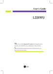
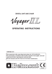
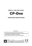
DENTAL UNIT
INSTALLATION
and
OPERATING INSTRUCTIONS
IMPORTANT
This manual provides operating instructions for the CLESTA.
The instructions contained in this booklet should be thoroughly read and
understood before operating the unit. After the installation has been
completed, keep this manual in a safe place and refer to it for future
maintenance.
If you have any questions about this Manual or this product, please contact us.
If manual becomes unreadable or is lost, please request a new manual
by contacting your dealer.
Installation should be conducted by authorized personnel only.
Follow instructions on installation manual.
0197
TABLE OF CONTENTS
Page
SAFETY PRECAUTIONS-------------------------------------------------- 1
1. GENERAL INTRODUCTIONS---------------------------------------- 5
2. INSTALLATION INSTRUCTIONS------------------------------------ 8
3. OPERATING INSTRUCTIONS ---------------------------------------- 19
4. DAILY MAINTANANCE------------------------------------------------ 23
5. MAINTANANCE AND INSPECTION
5-1. GUIDE FOR DAILY MAINTENANCE AND INSPECTION ----- 27
(Maintenance and inspection by user)
5-2. DUIDE FOR PERIODICAL CHECK-UP------------------------- 29
6. ELECTROMAGNETIC COMPATIBILITY (EMC)----------------- 30
7. LIST OF COMPATIBLE HANDPIECES------------------------------ 33
Intended Use of the Product
This product is an active therapeutic device intended for the exclusive use for diagnoses,
treatments and relative procedures of dentistry.
The product must be operated or handled by the qualified dentists or by dental staffs under
the supervision of the dentist.
Such dentists or dental staffs should instruct and/or assist the patients to approach to and leave
from the product.
Patients should not be allowed to operate or handle the product unless he/she is so instructed.
The product is supplied together with the handpieces like electric micromotor, air turbine
and/or motor, scaler and so on.
Compatibility of Handpieces
Use the compatible handpieces as shown on the attached list for this unit. (List of compatible
handpieces).
Important Notes
In case of the troubles, please contact Takara Belmont offices or your dealers.
Do not disassemble or attempt to repair.
Disassembly, repair or modifications should only be done by a qualified repair technician.
Attempts at disassembly, repair or modifications may lead to abnormal operation and accidents.
Disposal of residue material
Please request a special contractor when you dispose amalgam.
In case of disposal of equipment
When disposing the unit, appropriately dispose complying with all current applicable
regulations and local codes.
In EU area, EU directive 2002/96/EC on waste electrical and electronic equipment (WEEE) is
applied on this product. In this directive, environment conscious recycling/abandonment is
obligated.
SYMBOLS
In this manual, on the labels or on the control panel of CLESTA, following symbols are used.
Confirm the meaning of each symbol.
alternating current
Protective earth
(ground)
ON (power)
OFF (power)
Chair last position
Chair auto return
Chair preset 1
Chair preset 2
To raise the chair
To recline the
backrest
To lower the chair
To raise the
bacrest
Chair
manual control
Fiber optic
handpiece light
on/off
Micro motor
rotation speed
Scaler power
control
Micro Motor
Forward/Reverse
select
Syringe
Saliva ejector
Bowl flush
Cupfiller
Service outlet
(water)
Water heater
EC
REP
SN
Serial number
Authorized
representative in
the European
community
Caution
It means “caution,
warnings, or
possibility to
danger”.
Type B
applied parts
Refer to instruction
manual/booklet
W
Water
A
Air
Manufacturer
Date of
manufacture
Non-ionizing
radiaion
Separate
collection for
electrical and
electronic
equipment
SAFETY PRECAUTIONS
■ Before use, read the “Safety precautions” carefully to ensure proper use.
■ The following information is designed to ensure safe use of this product and to prevent injury and damage
to you and others. The precautions contained here are classified depending on the severity and degree of
imminence of possible injury or damage resulting from improper use. Be sure to follow all the
information, which is important for safety.
Severity and degree of imminence of possible injury or damage
Classification of precautions
WARNING
This symbol indicates that “ignorance of these precautions may lead to severe
injury or even death as a result of improper use.”
CAUTION
This symbol indicates that “ignorance of these precautions may lead to mild
or moderate physical injury or damage to property as a result of improper use.”
NOTICE
This symbol indicates that “it is recommended to follow these precautions
for safety.”
WARNING
1. Be sure to turn off breakers for equipment in the clinic when this product will not be used for a long
period of time
Be sure to turn off breakers for equipment in the clinic when this product will not be used for a long period of
time (following the completion of work, during the suspension of business, etc.). Insulation degradation may
cause electrical fire.
2. Be sure to turn off the main switch upon completion of work or during work breaks
Be sure to turn off the main switch upon completion of work or during work breaks. This prevents incorrect
operation due to accidental contact and associated hazards.
3. Do not sit on other than seat
When the backrest is at the forward position. do not sit on or place an undue load on the headrest or legreat of
dental chair. This could cause the unit to topple or could damage the unit.
4. Do not place an undue load on the arm
Do not get on or place an undue load on the arm of this unit or dental chair armrest. This could cause the unit
to topple or other accidents.
5. Be sure to establish a grounding connection
Be sure to establish a proper grounding connection. (Refer to a vendor for grounding connection.) Failure or
electric leakage may lead to electric shock.
6. Never disassemble, repair or modify this product
Individuals other than certified repair technicians should not disassemble or attempt to repair and modify this
product. This could lead to an accident, failure, electric shock or fire.
7. Use with caution in the presence of electromagnetic interference waves
Do not place this product around equipment generating electromagnetic waves (including communications
equipment, elevators, etc.) as incorrect operation of this product may occur in the presence of electromagnetic
interference waves. Do not use equipment generating electromagnetic waves, such as mobile phones, around this
product.
-1-
SAFETY PRECAUTIONS
WARNING
8. Be sure to turn off the main switch when electrocautery is in use
Be sure to turn off the main switch when electrocautery is in use, because noise may cause incorrect operation of
this product.
9. Ensure the maintenance of this product
• Failure to maintain this product may lead to physical injury or property damage.
• Refer to the section of maintenance.
10. Do not place objects weighing 3 kg or more on the Doctor's table
Do not place objects weighing three kilograms or more on the Doctor's table. This could cause damage to the
Doctor's table, defective function or accidents.
11. Be sure to use the mirror cover
• Be sure to use the mirror cover of the dental light when the light is turned on. Direct contact with lamps may cause burns.
• See the Instruction Manual of the dental light for further information.
12. Be sure to turn off the power when replacing lamps
• Be sure to turn off the power when replacing the dental light. This could result in electric shock.
• Use only dedicated halogen lamps.
• Immediately after a halogen lamp has burnt out, the lamp and the lamp holder are still hot. Replace the lamp after they cool down.
• Do not touch halogen lamps with bare hands.
• See the Instruction Manual of the dental light for further information.
13. Immediately wipe off any water spills or leakage on the floor
Immediately wipe off any water spills or leakage on the floor. Decreased strength of the floor may lead
to physical injury including fall, or property damage.
14. Use with caution on patients with a cardiac pacemaker
Use this product with extreme caution on patients with a cardiac pacemaker. In the case of any abnormalities in
patients during use, immediately turn off this product and discontinue use.
CAUTION
1. Only experienced personnel should use this product
Only dentists or other dental professionals should use this product.
2. Confirm safety before use.
Before use, confirm that the parts are correctly and safely operating and that there are no obstacles around this
product.
3. Pay attention to patients and children
Keep your eyes on patients (especially, children) so that mischief or inadvertent operation of equipment will
not lead to unexpected accidents.
4. Discontinue use if you feel that “something is wrong”
Always be careful to inspect this product for looseness, rattling, tilting, wobbling, sounds, temperature, odors,
etc. Immediately discontinue use at the first feeling that “something is wrong.”
-2-
SAFETY PRECAUTIONS
CAUTION
5. keep your eyes on the patient during operation.
• Confirm that the patient is seated in the proper position. Keep your eyes on the patient during the operation.
• Pay special attention to surroundings at automatic operation of the dental treatment table. Damage to the
backrest, stool or Doctor's table may occur.
6. Pay attention during movement of the Doctor's table
• Pay attention to surroundings when you move the Doctor's table. Injury by the tips of handpieces, etc.,
may occur.
• Be sure to move the Doctor's table by holding the handle of the unit.
• Be sure to move up & down the Doctor's table by releasing the balance arm brake of the unit.
7. Do not place anything hot on the Doctor's table
Do not place anything hot on the Doctor's table. This could cause deformation or discoloration.
8. Cautions when adjusting the height of the cart-type instrument table (Cart type only)
After adjusting the height, be sure to fasten the loosened lock screw. Failure to heed this warning may cause the
table to drop, resulting in an accident.
9. Observe the cart hose (Cart type only)
Do not tread on the cart hose. Failure to heed this warning may result in damage to the hose, as well as people
tripping over.
10. Do not smack or rub this product
Do not smack or rub this product forcefully. This could cause damage to covers or defective function.
11. Precautions for cleaning a spittoon bowl
The spittoon bowl is made of glass. Handle with care. Do not wash it with hot water. Otherwise, it may break.
12. Precautions for cleaning the resin cover
For cleaning, do not use cleaning agents containing solvent or abrasives, thinners or oil-based alcohol (butanol
and isopropyl alcohol), which may cause cracks.
13. Immediately wipe off drug solution when it comes into contact with this unit
Should drug solution or water comes into contact with this unit, immediately wipe it off with a dry soft towel,
etc. This could result in defective function or electric leakage as well as spotting or rusting.
14. Close the water main valve and turn off the main switch upon completion of work
Be sure to close the water main valve and the main switch at the end of each work day to prevent water leakage
from occurring.
15. Be sure to operate switches with your hands
Be sure to operate switches with your hands, except the foot controller, which is operated with your foot.
Operation with body parts other than hands may cause damage or incorrect operation.
16. Pay attention during the headrest operation
Do not allow hands, fingers, or hair to become entangled in the moving parts of the headrest during operationg
17. Be careful not to heat an empty water heater
Exercise caution as heating of an empty water heater may result in burning of the heater, leading to fire.
-3-
SAFETY PRECAUTIONS
CAUTION
18. Precautions for cleaning the operation panel (membrane switches)
Penetration of droplets of sanitizing spray into the back of the operation panel may be associated with switch failure.
Use a paper towel soaked with sanitizing solution to clean the surface of the operation panel.
19. Precautions for cleaning
• Never use sandpaper, metal scrub brushes and abrasive cleaning agents to clean the unit.
• Do not use strongly acidic cleaning agents or alkaline pipe cleaning agents to avoid corrosion of metals, etc.
20. Set the pressure of the water tank at 200 kPa or less
Adjust the air supply pressure for the water tank to 200 kPa or less. An excessively high pressure may cause
damage to the water tank.
21. Do not use water other than purified water, distilled water or pure water for the water tank
The water tank is intended only for use with purified water, distilled water and pure water. Do not use mouthwash
or electrolyzed water, such as ConCool or povidone iodine, as they may cause clogged tubing or affect internal
valves and equipment.
22. Precaautions for insert the bowlflush nozzle and the cupfiller nozzle to the spittoon bowl
After cleaning of the spottoon section, be sure to insert the nozzles straightly to spittoon bowl. If not, it may be
damage the o-ring and it may leak the water.
23. Read the documents accompanying the various pieces of equipment
Before use, be sure to carefully read the package inserts and Instruction Manuals accompanying the various
pieces of equipment (including optional articles) to ensure proper use.
NOTICE
1. Troubleshooting and contact information
In the case of any problems, discontinue use, turn off the main switch and contact the dealer or our company.
2. Check operation of the compressor
With no air supplied, this product does not operate even after turning on the main switch. Turn on the power of
the compressor before operating this product.
3. Precautions when using water other than tap water
The water unit is intended for use with tap water. Caution should be exercised as the use of water other than
tap water (water through a sterilizer of water systems, etc.) may result in failure of equipment.
4. Use the turbine with a water check valve
Use the turbine with a water check valve. Contact the dealer or our company when a turbine without a water
check valve will be used.
5. Handling of equipment in the case of a power failure
Put the handpiece in the holder and turn off the main switch if equipment stops working during use due to a power
failure or other reasons.
-4-
[1] GENERAL INTRODUCTIONS
(1) UNIT TYPE VARIATIONS & MAJOR PARTS IDENTIFICATIONS
1. UNIT MOUNT TYPE
Light Pole
Cupfiller Nozzle
Bowl Flush Nozzle
Cuspidor Top
Assistant Holder Bar
Saliva Ejector
Dental Light
Horizontal Arm
Dental Size Film
Viewer
Syringe
Control Panel
High Volume
Evacuator
Assistant Holder
Balance Arm
Light Post
Cuspidor Unit
Doctor Table Tray
Waste Receptacle
Handle
Umbilical Hose
Syringe
Handpiece Holder
Handpiece Tubing
Foot Control
Junction Box
Fig.1-1 Overview
-5-
Handpieces
(Air Turbine, Air Motor, Scaler and etc.)
Manufacturers recommend to
use the handpieces with CE markings.
2. SPLIT CART HOLDER TYPE WITH CUSPIDOR
Dental Size
Film Viewer
Doctor Table Tray
Handle
Umbilical Hose
Cart Hose
Junction Box
Cart Base
Foot Control
Caster
Fig.1-2 Overview
-6-
(2) DIMENSIONS
-mm-
610
330
330
650
90
783
52
188
423
180
90
860
562
14°
171
364
76
98
287
529
521
905
38°
98
250
Fig.1-3 Dimensions
294
493
(3) SPECIFICATIONS
Rated power supply ------------------------------------------------- AC230V 50/60HZ 0.7A
Air main pressure --------------------------------------------------- 0.45 to 0.5MPa
Water main pressure ------------------------------------------------ 0.1 to 0.2MPa
Net weight ----------------------------------------------------------- 80.5kg (without dental light)
Dental light ---------------------------------------------------------- AL-501
Working environment ----------------------------------------------- Temperature : (Operating) +5℃ ~ +40 ℃
(Storage) -10℃ ~ +50℃
Humidity : 10 ~ 80%
Atmospheric pressure : 600hPa ~ 1060hPa
Service Life ----------------------------------------------------------- 10 Years
Classification of foot controller ------------------------------------ IPX1 (applicable standard IEC60529)
Protection class against electric shock ---------------------------- Class I equipment
Applied parts --------------------------------------------------------- Type B applied parts : Handpiece for unit
(List of compatible handpieces)
Equipment that is not suitable for use in air, flammable anesthetic gas, oxygen or nitrous oxide
-7-
[2] INSTALLATION INSTRUCTIONS
(1) PREPARING FOR INSTALLATION
The recommended location, plumbing and layout of junction box are shown in Fug.2-1, 2-2 and
MIN.600
130
2-3 respectively.
1. LOCATION AND PLUMBNG LAYOUT OF JUNCTION BOX Standard Type
220
MIN.800
CM/OP MIN.1000
SC MIN.1200
CENTER OF CLESTA CHAIR
VACUUM WATER
DRAIN
POWER
SOURCE
85
121
527
Fig.2-1 Location and Plumbing Layout
-8-
VACUUM
OPERATING
311
70
55
70
243
110
175
135
AIR
MIN.600
130
Belmont Type
220
MIN.800
CM/OP MIN.1000
SC MIN.1200
VACUUM
70
DRAIN
70
243
110
VACUUM
OPERATING
POWER
SOURCE
AIR
121
80
527
Fig.2-2 Location and Plumbing Layout
NOTE: CM/OP ..... CHAIR MOUNT OVER THE PATIENT TYPE
SC ............ SPLIT CART TYPE -9-
311
140
WATER
175
CENTER OF CLESTA CHAIR
2. PLUMBING HEIGHT OF JUNCTUON BOX
VACUUM
C
20
40
F
E
G
D
DRAIN
AIR & WATER
30
B
80
A
POWER SOURCE &
VACUUM OPERATING
Fig.2-3 Plumbing Height
A : NIPPLE
B : SOCKET JOINT
C : AIR
WATER
D : DRAIN
E : POWER SOURCE
SUPPLY CABLE
EARTH WIRE
F : VACUUM
; PT 1/2 - 1/2 (Brass)
; Unplasticizied Polyvinyl Chloride Pipe Fitting
; Unplasticizied Polyvinyl Chloride Pipe (Shock Resisting Type)
'HI13' 18mm O.D. - 13mm I.D.
; Unplasticizied Polyvinyl Chloride Pipe for Water Works Service
'VP 13' 18mm O.D. -1 3mm I.D.
; Unplasticizied Polyvinyl Chloride Pipe 'VP 40'
48mm O.D. - 40mm I.D.
; Unplasticizied Polyvinyl Chloride Conduit 'VE 16'
22mm O.D. - 16mm I.D.
; Polyvinyl Chloride Insulated and Sheathed Cable 'VVF 2.0-2C'
; Polyvinyl Chloride Insulated Wire 'VE 1.6'
; Unplasticizied Polyvinyl Chloride Pipe 'VP 20'
26mm O.D. - 20mm I.D.
G : VACUUM OPERATING ; Unplasticizied Polyvinyl Chloride Conduit 'VE 16'
22mm O.D. - 16mm I.D.
-10-
[2] INSTALLATION PROCEDURES
1. CHECK THE PACKING
Check each quantity of the parts for installation as listed below.
*Standard Specification
1) SHUT OFF VALVES FOR AIR & WATER 2) WOOD SCREW
3) FLEXIBLE PIPE
4) DRAIN ELBOW 5) VACUUM ELBOW 6) DRAIN CAP
7) BASKET STRAINER
8) CUPFILLER NOZZLE
9) BOWL FLUSH NOZZLE 1SET
4PCS.
2PCS.
1PCE.
1PCE.
10) SALIVA EJECTOR TIP 11) VACUUM TIPS (BENT & STRAIGHT) 12) SILICON TIP
13) LEVEL ADJUSTMENT SCREW 14) WASTE RECEPTACLE 15) LIGHT POLE
16) SILICON MAT FOR DR.TABLE 17) WIRE CONNECTOR
18) SEAL
19) PATIENT CUP
20) VIALS WITH STAND
21) COTTON CONTAINER WITH STAND 21) MOUNTING BRACKET COVER 1PCE.
1PCE.
1PCE.
1PCE.
1PCE.
1SET
10PCS.
4PCS.
1PCE.
1SET
1PCE.
3PCS.
4PCS.
1PCE.
1SET
1SET
1PCE.
Flat Head Screw
Seal
Cuspidor Unit
Stopper
Screw
Mounting Bracket
2. ATTACH UNIT TO CHAIR
2-1. Mounting bracket A Type (Fig.2-4)
1) Raise the upper structure of dental chair to
Spring Washer
Nut
Mounting
Bracket A
the highest position.
2) Install the cuspidor unit on Mounting
Bracket A Type with 4pcs.of M10-50 Flat
Head Screws, Spring Washer and Nuts.
Level Adjustment Screw
Stopper
Screw
3) Adjust the level of cuspidor unit with 4pcs.
of M10-25 Level Adjustment Screws.
4) Stick the Seals over the Flat Head Screws.
5) Remove the stopper screw from the
mounting bracket.
Mounting Bracket
Cover
6) Attach the mounting bracket cover on the
mounting bracket, and fix with the stopper
screw.
Fig.2-4 Attach Unit to Chair
-11-
2-2. Mounting Bracket B Type (Option) (Fig.2-5)
1) Raise the upper structure of the dental chair
to the highest position.
2) Attach the Adaptor to Mounting Bracket B
Type with 4pcs. of the M10-40 Socket Head
Cap Screws and Spring Washers.
3) Install the cuspidor unit on Mounting
Bracket B Type with 4pcs. of M10-50 Flat
Head Screws, Spring Washer and Nuts.
4) Adjust the level of cuspidor unit with 4pcs.
of M10-25 Level Adjustment Screws.
5) Stick the Seals over the Flat Head Screws.
6) Remove the stopper screw from the
Flat Head Screw
Cuspidor Unit
Seal
Stopper
Adaptor
Socket Head
Screw
Mounting Bracket
Spring
Washer
Spring Washer
Nut
Level Adjustment Screw
Mounting Bracket B
Stopper
Mounting Bracket
Cover
mounting bracket.
7) Attach the mounting bracket cover on the
mounting bracket, and fix with the stopper
screw.
Fig.2-5 Attach Unit to Chair
3. INSTALL DENTAL LIGHT (Fig.2-6)
1) Remove Cover from the bottom of the unit
2) Put Plastic Washer on the Light Pole.
3) Run the Cable through Light Pole and attach
the Dental Light to the Light Pole.
4) Run the Cable through Light Post and install
the Pole, then tighten 2pcs. of the Set Screws.
Dental Light
Plastic Wahser
Light Pole
Set Screw
5) Connect the wires from the Dental Light
and Cuspidor Unit in accordance with the
identification color.
6) Re-attach the Cover.
Cover
Cable from
Dental Light
Cable from
Cuspidor Unit
Fig.2-6 Install Dental Light
-12-
4. CONNECT UMBILICAL HOSE WITH
JUNCTION BOX (Fig.2-7, 2-8 & 2-9)
Umbilical Hose
This section is only for SPLIT CART TYPE.
For other type of unit, proceed to 5.
1) Open the cover of Junction Box by
loosening two screws.
2) Loosen the screw of Umbilical Hose Clamp.
3) Insert all hoses, tubings and wirings of
Umbilical Hose Clamp
Umbilical Hose from Cuspidor unit into
Junction Box through the Umbilical Hose
Clamp.
Fig.2-7 Connect Umbilical Hose
Blue 5/16”
Brown 1/8”
4) Correct the twist of the Umbilical Hose
as the Junction Box is placed at the planned
location.
5) Set the end of Umbilical Hose at the
Umbilical Hose Clamp then re-tighten the
screw for the Umbilical Hose Clamp.
6) Connect tubings with nylon sleeves to the
Yellow 1/4”
Wirings for
Water Heater
& Dental Light
Light Green 1/4”
fittings as shown in Fig.2-8 or 2-9.
7) Connect wirings to Electric Terminal as shown in Fig.2-8 or 2-9.
1 2 3
4
4
White
4
1 2 3
White
5
5 6 7 8
4
4
5
5
5
4
Black
5 6 7 8
Black
Fig.2-8 Standard Specification
* How to connect wiring to the Electric Terminal
(Fig.2-10)
During pressing the slot of the Electric Terminal
by the Small Thin Screw Driver, insert the wiring
Blue 1/16”
Brown 1/8”
to the Electric Terminal.
Yellow 1/4”
Wirings for
Dental Light
Light Green 1/4”
Wirings for
Water Heater
Small thin Screw Driver
Electric Terminal
Blue
Wiring
L
Brown
Line Voltage
24V
Brown
Fig.2-10 How to Connect Wiring
L
C
C
Blue
Fig.2-9 Low Voltage Specification
-13-
5. CONNECT UTILITY SECTION
(Fig.2-11& 2-12)
1) Attach Shut Off Valves to the air and water
supply lines, pointing to proper directions
for further connections.
2) Attach Electrical Receptacle to Main Power
Supply Cable.
(The Electrical Receptacle must be prepared
locally.)
Standard Type
Belmont Type
Center of Clesta Chair
Center of Clesta Chair
Air Shut
Off Valve
Water Shut
Off Valve
Water Shut
Off Valve
Electrical
Receptacle
Air Shut
Off Valve
Shut Off Valve
3) Open each Shut Off Valve to remove any
chips or dirt in the air and water supply
line, then close the Valves.
4) Open the cover of Junction Box by
Electrical
Receptacle
Nipple
loosening two screws, and place Junction Box at the planned location, then fix it on
the floor with 4pcs. of Wood Screws.
5) Cut the Drain Hose and the Vacuum Drain
Hose at the proper length, and connect and
glue them to each elbow.
6) Connect the Vacuum Elbow to the Suction
Fig.2-11 Connect Supply Lines
Vacuum Drain Hose
Wood Screw
Drain Hose
Pipe.
7) Insert the Drain Elbow into the Drain Pipe.
Drain Elbow
Vacuum Elbow
Fig.2-12 Connect Drain Lines (1)
Vacuum Drain Hose
* Attaching Drain Bushing (Option) to the
Drain Pipe is desirable, and Drain Elbow
should be bonded firmly into the Drain Pipe.
Vacuum Elbow
Drain Elbow
Drain Hose
* For Air Vacuum specification, prepare Drain
Joint(Option) as shown in Fig.2-13, so that
the drain line and the vacuum drain line may
be inserted together into the Drain Pipe.
Vacuum Pipe
Drain Pipe
Drain Bush
(Option)
Drain Joint (Option)
Drain Bush (Option)
Fig.2-13 Connect Drain Lines (2)
-14-
See Fig.2-14 & 2-15.
8) Connect Water Shut Off Valve and Water
Filter
Filter with Stainless Flexible Pipe and
Packing. Connect Air Shut Off Valve and
Filter
Air Filter in the same way.
Packing
Shut Off Valve
Fig.2-14 Connect Filters (1)
Standard Type
Air Filter
Water Filter
Belmont Type
Water Filter
Air Filter
Fig.2-15 Connect Filters (2)
See Fig.2-16 or 2-17.
9) Prepare the Electrical Plug, and connect it to
Main Power Supply Cable.
(Electrical Plug must be prepared locally.)
10) Connect Vacuum Operating Cable to the
Electric Terminal as shown in Fig.2-16 or
2- 17.
(For Central Vacuum Specification only)
11) Run the three cables from chair (Power
Supply Cable with plug, Cable with 9P
connector and Cable with 4P connector),
through the hole of the Junction Box wall
above the Umbilical Hose into the Junction
Box.
Cable for Chair Control (9P)
Plug
Cable from
Chair
Vacuum
Operating
Cable (9P)
Main Power
Supply Cable
1 2 3
1 2 3
4
4
4
5
4
5 6 7 8
5
Cable for Chair
Safety Device
(4P)
Vacuum
Operating Cable
5 6 7 8
Fig.2-16 Connect Electrical cable (1)
Cable for Chair Control (9P)
12) Connect the Power Supply Cable of the
chair to the receptacle, and connect other
two cables to the corresponding connectors.
Plug
Cable from
Chair
Main Power
Supply Cable
Vacuum
Operating
Cable (9P)
Cable for Chair
Safety Device
(4P)
Vacuum
Operating Cable
Fig.2-17 Connect Electrical cable (2)
-15-
6. ATTACH FILM VIEWER (Fig.2-18 &2-19)
1) Remove the Doctor Table Tray by loosening
eight Flat Head Screws.
Flat Head Screw
2) Run the cable from Film Viewer into Doctor
Table.
3) Attach Film Viewer to the bracket for Doctor
Table with two Philips Screws.
4) Connect the cable from Film Viewer to the
Doctor
Table
Tary
Electrical Terminal.
Film
Viewer
Philips Screw
Electrical
Terminal
Fig.2-18 Attach Film Viewer
Electrical Terminal
Fig.2-19 Connect Wirings for Film Viewer
7) SET UP CUSIPDOR TOP (Fig.2-20)
1) Insert Cupfiller Nozzle and Bowl Flush
Nozzle, and tighten each nut.
Cupfiller Nozzle
2) Put Basket Strainer and Drain Cap into the
cuspidor bowl.
Bowl Flush Nozzle
Drain Cap
Basket Strainer
Fig.2-20 Cuspidor Top
-16-
(3) ADJUSTMENT BEFORE USE
1. AIR & WATER SUPPLY LINE
Pull Up
(Fig.2-21 & 2- 22)
1) Check the Air Pressure Gauge on the side
of Junction Box.
Knob
Push Down
decrease
Increase
The Pressure should be approximately
0.45Mpa to 0.5Mpa for air.
For adjustment the pressure, pull up and
turn the knob of Air Regulator while the air
Air Regulator
is flowing (use 3-way Syringe for example).
To increase the pressure, turn clockwise.
To decrease, turn counter-clockwise.
After adjustment, push down the knob to fix it.
Increase
2) Check if the Water Pressure Gauge indicates
the pressure at around 0.1Mpa to 0.2Mpa.
Adjustment can be done by Water Regulator.
To adjust the pressure, lift and turn the water
regulator knob until the water starts flowing.
(use 3-way Syringe for example).
To increase the pressure, turn clockwise.
To decrease, turn counter-clockwise.
After adjustment, lower the knob back in place.
3) As the unit is ready to run, turn on the Master
Switch located underneath the doctor table
(see Fig.2-23.), then run the saliva ejector for
a while to flow the water through the unit and
make sure no leakage takes place at the utility
section.
Water Regulator
Knob
Push Down
decrease
Pull Up
Fig.2-21 Inside of Junction Box
Air Pressure Gauge
Water
Air
Water Pressure Gauge
Fig.2-22 Side View of Junction Box
Master Switch
ON
See Fig.2-23 & 26.
4) Turn all Coolant Water Control Knobs counter-
OFF
clockwise fully and pick up all handpiece tubing
from the holder, then depress Drive Pedal of the
foot control (Spray Switch -ON) for a moment
to flush out the water from the tubing into the
cuspidor bowl.
Coolant Water
Control Knob
Increase
decrease
Fig.2-23 Bottom View of Doctor Table
-17-
2. Drive Air & Spray for Handpieces
(Fig.2-24, 2-25 & 2-26)
1) Connect handpieces to each tubing, and
Flat Head Screw
make adjustment one by one.
2) To adjust the drive air pressure for each
handpiece, turn the appropriate Adjust
Screw for Drive Air one the Auto-Select
Valve in the doctor table.
Turn the screw clockwise to close the line
fully. Then during depressing Drive Pedal
Auto-Select
Valve
Doctor
Table
Tray
of Foot Control fully, gradually increase
the sir flow by turning the screw counter clockwise up to Handpiece Pressure Gauge
reads the full recommended pressure.
3) To adjust spray of handpiece, use Adjust
Pressure
Gauge
Screw for Coolant Air on the Auto-Select
Valve and Coolant Water Control Knob.
Fig.2-24 Inside of Doctor Table
Adjust Screw
for Drive Air
Adjust Screw
for Coolant Air
Fig.2-25 Auto-Select Valve
Drive Pedal
Fig.2-26 Foot Control
-18-
[3] OPERATION INSTRUCTIONS
(1) DOCTOR UNIT SECTION
Film Viewer
Power Indicator
1. MASTER SWITCH (Fig.3-1 & 3-2)
1) Turn on the Master Switch and the Power
Indicator is lit in green.
2) After the operation, turn off the Master
Membrane Switch A
Switch, then the supplies of air, water and
electricity are all shut down at the utility
section.
Brake Release Button
Membrane Switch B
2. TABLE POSITION (Fig.3-1)
Handpiece Holder
For standard model of the chair mount over
patient type, the height of the doctor table is
always fixed by Air Brake. The height can
be easily changed by pressing Brake Release
Button.
3. CHAIR CONTROL (Fig.3-3)
The chair movement can be controlled by
pressing Chair Control on Membrane Switch A.
Please refer to operating instructions for chair.
Fig.3-1 Doctor Unit
Master Switch
Air
Water
ON
OFF
Coolant Water
Control Knob
Flow Control Knob
for 3-Way Syringe
Fig.3-2 Bottom View
Cupfiller Switch
4. CUPLILLER & BOWL FLUSH CONTROL
(By AIR TIMER SYSTEM) (Fig.3-3)
By pressing each membrane switch, water is
Chair Automatic Control
1
2
0
LP
supplied for a certain time.
For cupfiller, filling time is set for 4 seconds at
Bowl Flush Switch
factory.
Chair Manual Control
For bowl flush flushing time is set for 6 seconds
Fig.3-3 Membrane Switch A
at factory.
5. 3-WAY SYRINGE (Fig. 3-2 & 3-4)
1) By pressing either or both buttons, Syringe
offers air, water and spray.
2) Syringe Tip can be rotated freely.
3) To adjust air/water/spray, use Flow Control
Knobs located underneath the doctor table.
Air Button
Water Button
wA
Syringe Nozzle
Fig.3-4 3-Way Syringe
-19-
6. OPERATING HANDPIECE (Fig.3-5)
1) Pick up a handpiece from the pandpiece
holder, and depress Drive Pedal of Foot
Coolant Water Switch
Control.
2) For the dry-cutting, turn off Spray Switch
of Foot Control.
3) While depressing Chip Pedal, only the chip
ON
OFF
Drive Air Pedal
blow comes out from the handpiece.
Chip Blower Button
Fig. 3-5 Foot Control
7. FILM VIEWER (Fig.3-6)
Film Viewer Switch is located on the right
side of film viewer. Press the switch once to
illuminate the viewer, press it again to turn it off.
8. FIBER OPTIC HANDPIECE (OPTION)
( Fig.3-7)
Fiber Optic Handpiece Switch is located on
the Membrane Switch B.
Pick up a optic handpiece from the handpiece
holder and the handpice is lit. Return the
handpiece to the holder and it is put out.
9. ELECTRIC SCALER (OPTION) (Fig.3-7)
Power Control for Electric Scaler is located
under the Membrane Switch B.
Film Viewer Switch
Fig. 3-6 Film Viewer
Fiber Optic
Handpiece
Switch
2
3
1
4
0
5
Power Control for
Electric Scaler
CAUTION
Handpieces
Refer to handpiece manufacturers operating instructions.
-20-
Fig. 3-7 Membrane Switch B
(2) ASSISTANT UNIT SECTION
1. CUPFILLER & BOWL FLUSH CONTROL
(By AIR TIMER SYSTEM) (Fig.3-8)
By pressing each membrane switch, water is
Bowl Flush Switch
supplied for a certain time.
For cupfiller, filling time is set for 4 seconds a
factory.
For bowl flush. Flushing time is set for 5 seconds
at factory.
Cupfiller Switch
Fig.3-8 Membrane Switch for Assistant
2. 3-WAY SYRINGE (Fig.3-4 & 3-9)
1) By pressing either or both buttons, Syringe
offers air, water and spray.
Increase
2) Syringe Tip can be rotated freely.
3) To adjust air/water/spray, use Flow Control
Knobs located in the cuspidor body.
decrease
Cupfiller Flow
Control Knob
3. MASTER VALVE BLOCK (Fig.3-9)
Open the side panel of the cuspidor body.
Flow Control knobs for Cupfiller and
Bowl Flush are accessible.
Bowl Flush Flow
Control Knob
Water Flow Control
Knob for 3-Way
Syringe
Air Vacuum Flow
Control Knob
Air Flow Control
Knob for 3-Way
Syringe
Fig.3-9 Master Valve Block
4. CUSPIDOR BODY ROTATION &
TELESCOPIC ASSISTANT HOLDER BAR
(Fig.3-10)
1) Cuspidor Body can rotate by 90 degrees for
assistant’s convenience.
2) For two-hands treatment, Assistant Holder
Bar can be extended by 50cm.
Telescopic
Assistant
Holder bar
5. ASSISTANT INSTRUMENT HOLDER
(Fig.3-10)
Pick up the instrument (Saliva Ejector or High
Volume Evacuator) from the holder, and it starts
working.
-21-
Assistant
Holder
Fig.3-10 Cuspidor Unit
6. WATER HEATER SWITCH (Fig.3-11)
Turn on the Water Heater Switch when the warm
water for the patient cup is required.
Water Heater Switch
7. SERVICE WATER OUTLET WITH FLOW
CONTROL (Fig.3-11)
Bowl Flush Switch
Water Outlet with Flow Control is located on the
panel which adapts to the quick connector.
8. BOWL FLUSH SWITCH (OPTION) (Fig.3-11)
Turn on the Bowl Flush Switch and the water is
flushed to the bowl continuously.
9. AUTOMATIC CUPFILLER &
BOWL FLUSH (OPTION) (Fig.3-12)
1) Place the patient cup weighting 45 to 80g
on Cup Base and water is supplied for a
certain quantity to the patient cup and flushed
for a certain time to the bowl.
2) Quantity of water in patient cup can be
adjusted by turning Cup Base.
Service Water Outlet
Flow Control Knob for
Service Water Outlet
Fig.3-11 Cuspidor Control Panel
-
+
Cup Base
Fig.3-12 Automatic Cupfiller
(3) LIGHT SECTION (MODEL IO 5000)
1. MODE SELETION SWITCH (Fig. 3-13)
Turn the switch to SENSOR side, and ON/OFF
of the light can be made by approaching hand of
the sensor. (Touchless Switch).
MANUAL
SENSOR
Fig.3-13 Mode Selection Switch
2. INTENSITY SWITCH (Fig. 3-14)
Then intensity of light can be selected L (Low),
M (Medium) or H (High).
Refer to the manual of IO 5000.
H
H
Touchless Switch
M
Fig.3-14 Intensity Switch
-22-
L
[4] DAILY MAINTENANCE AND CARE
(1) DRAIN & SUCTION LINE OF UNIT
(Fig.4-1)
Drain Cap
1. Basket Strainer.
Remove the Basket Strainer Cap, and clean
Solid Collector
Basket
Strainer
the Basket Strainer.
2. Solid Collector Filter
Open the side panel of the cuspidor body and
take out Solid Collector Filter and clean it.
Pulling on the Solid Collector Cap will bring
the Solid Collector Filter with it.
Solid Collector Filter
Fig.4-1 Basket Strainer & Solid Collector
(2) AIR SUPPLY LINE (Fig.4-2)
1. Air Filter Drain Valve
1) Release the water in the air filter by opening
Drain Valve of Junction Box.
2) Turn off the main switch of the compressor.
Release compressed air and drain according
to the instructions of the compressor.
Confirm the air Pressure Gauge indicates
0Mpa.
(3) HANDPIECE
1-1.Vacuum Handpiece and Saliva Ejector Handpiece
For effective sterilization, washing for removing
contamination and immersion by a cleaning agent
are required. Then, rinse by water in order to
remove residual cleaning agent on medical device.
Take following procedures from cleaning to
sterilization.
* Use the disposable saliva ejector tip.
Drain Valve
Air Pressure
Gauge
Fig.4-2 Junction Box
Vacuum Tip
Vacuum Cap
Saliva
Ejector
Cap
Filter
Slide Knob
Vacuum
Handpiece
Body
Disassembly (Fig.4-3)
Disassemble the handpiece for the preparation of
cleaning as the following figures show.
Pull the hose connector to disconnect the
vacuum hose.
-23-
Vacuum
Hose
Slide Knob
Saliva Ejector
Handpiece
Body
Hose Connector
Saliva Ejector
Hose
Fig.4-3 Vacuum Hndpiece &
Saliva Ejector Handpiece
Cleaning by hand
A. Wipe off the surface contamination by a cloth while rinsing
the surface by running clean warm water at 40±5 degrees.
(Fig.4-4)
Scrub the intubation or hole, slide groove and filter by a
Cloth
Fig.4-4 Surface cleaning
cleaning brush or by a tooth brush with running clean warm
water at 40±5 degrees. (Fig.4-5) Wipe off by a cloth for the
area which brush is unable to reach. (Fig.4-6)
B. Rinse thoroughly by distilled water at ordinary
temperature or by clean water for more than 1 minute.
Fitting cleaning brush
or Tooth brush
C. Check whether contamination is removed or not after cleaning.
Continue the cleaning if contamination is remained.
D. Immersed with an alkaline detergent for 5 minutes.
Slide groove
Fig.4-5 Cleaning of hole and sliding part
(We recommend to use ID212 made by DURR)
E. Rinse thoroughly by distilled water at ordinary
Cloth
temperature or by clean water for more than 1 minute.
CAUTION
Fig.4-6 Cleaning the area
(brush is unable to reach)
Cleaning must be done within 1 hour after use.
Throw out and do not take autoclave handpiece for
following cases.
• Any waste material can not be removed by clogged hole.
• Contamination and solid material attached to handpiece
can not be removed.
Sterilization (Fig.4-7)
Vacuum Tip/Vacuum Cap/ Vacuum Handpiece Body/Saliva Ejector
Handpiece Body can be autoclave. Vacuum handpiece body and
saliva ejector body have to assemble before autoclave.
A. Insert the handpiece in a sterilization pouch and seal it.
B. Autoclave for 20 min. at 121℃ or 4 min. at 135℃.
Sterilization with autoclave is permitted up to 250 times.
Sterilization pouch
Fig.4-7 Vacuum Handpiece and Saliva
Ejector Handpiece
CAUTION
• Sterilization by class B cycles.
• Sterilization temperature is 135 degrees or less.
• The cap, filter and body are made of resin. They may become deteriorated if they are
sterilized in an autoclave many times.
• After autoclave sterilization, the cap, filter, body and valve are subject to discoloration,
which does not have a negative effect on performance.
• The slide knob can be autoclave 100 times and is expendable supplies.
• Skip the drying process if the temperature is to exceed 135℃.
• If damage occurs to the sterilization pouch, discard and sterilize again using a new pouch.
Storage
After cleaning the vacuum tip, keep it in the clean place.
-24-
1-2. Cleaning vacuum and saliva ejector lines (Fig.4-8)
The sucking unit comes into contact with secretions, spit and blood that contain bacteria every day. Be sure to clean and sterilize
it at the end of each work day.
Recommended cleaner : Orotol Plus made by DURR.
CAUTION
Fig.4-8 Cleaning Vacuum /
Saliva Elector Lines
Do not use strongly acidic cleaning agents or alkaline pipe
cleaning agents, which may cause corrosion of metals, etc/
2. Vacuum Hose / Saliva Ejector Hose (Fig.4-9)
It is practical to remove the hoses in order to clean them.
Note: At the end of the day, clean the vacuum and
saliva ejector handpieces by sucking in two
cups’ worth of water.
3. AIR MOTOR / TURBINE / 3-WAY SYRINGE
Sterilize the handpiece according to manufacturer’s
operating manual.
4. Belmont 77 Syringe (Fig.4-10)
Disassembly
Remove the nozzle from syringe by turning it in direction A.
Cleaning by hand
A. Wipe off the surface contamination by a cloth while rinsing
the surface by running clean warm water at 40±5 degrees.
Scrub the tip and joint part of nozzle by a cleaning brush or
by a tooth brush with running clean warm water at 40±5
degrees. (Fig.4-11)
B. Rinse thoroughly by distilled water at ordinary temperature
or by clean water for more than 1 minute.
C. Check whether contamination is removed or not after cleaning.
Continue the cleaning if contamination is remained.
D. Immersed with an alkaline detergent for 5 minutes.
(We recommend to use ID212 made by DURR)
E. Rinse thoroughly by distilled water at ordinary temperature
or by clean water for more than 1 minute.
CAUTION
Fig.4-9 Vacuum Hose &
Saliva Ejector Hose
wA
Syringe body
A
Nut
B
Nozzle
Cleaning must be done within 1 hour after use.
Throw out and do not take autoclave handpiece for following cases.
• Contamination and solid material attached to handpiece can not
be removed.
-25-
Saliva
Ejector
Hose
Vacuum
Hose
Fig.4-10 Belmont 77 Syringe
Cleaning brush
or Tooth brush
Fig.4-11 Cleaning Belmont
77 Syringe Nozzle
Sterilization (Fig.4-12)
The nozzle can be sterilized with autoclave. A. Insert the handpiece in a sterilization pouch and seal it.
B. Autoclave for 20 min. at 121℃ or 4 min. at 135℃.
Sterilization with autoclave is permitted up to 250 times.
Apply Vaseline thinly and evenly to the two O-rings
after sterilization.
Tighten the nut firmly in direction B to undo the nozzle.
Sterilization pouch
Fig.4-12 Sterilization Belmont 77 Syringe Nozzle
CAUTION
•
•
•
•
Sterilization by class B cycles.
Sterilization temperature is 135 degrees or less.
Skip the drying process if the temperature is to exceed 135℃.
If damage occurs to the sterilization pouch, discard and
sterilize again using a new pouch.
• Before use, make sure that the nut is firmly tightened.
Storage
After cleaning the nozzle, keep it in the clean place.
(4) HOSES AND TUBING
Clean hoses and tubing using DURR FD333.
(5) CLEANING UNIT
All surfaces can be cleaned with DURR FD333 cleaner.
Spray the cleaner (FD333) on cloth and wipe the surfaces with the cloth.
CAUTION
Do not drench the unit. Wipe all surfaces dry after cleaning.
(6) LUBRICATING HANDPIECES
Refer to the manual of the handpieces.
(7) MASTER SWITCH
After the daily operation and maintenance, turn off the Master Switch.
Air Filter
(8) FILTER REPLACEMENT (Fig.4-13)
The water filter in the junction box needs to
be replaced at least once a year.
The air filter in the junction box needs to be
replaced at least once every three years.
Contact your local service representative for
replacement.
Water Filter
Fig.4-13 Filter
-26-
[5] MAINTANANCE AND INSPECTION
5-1. Guide for daily maintenance and inspection (Maintenance and inspection by user)
•Management of maintenance and inspection of medical equipment should be implemented by the
user (medical institution). In case the user does not implement such management, it is permitted
that such management is outsourced to a qualified entity such as a medical equipment repair
company.
• For safe use of this product, it is necessary that inspection should be conducted in the specified
frequency on the tems described below.
No.
Item
Frequency
Influence if inspection
not conducted
Inspection method
and diagnosis
Maintenance required in case
of nonconformity
㸦 Check
of safety
functions
Before
start
Make sure the chair
movement stops by any of
the following actions.
ձwhen foot controller pedal
is depressed.
ղDuring chair auto
movement, depress of any
operation switch.
ճWhile setup is in progress
with function switch on the
doctor membrane switch panel.
մWhen the spittoon bowl is
turned to patient side
(Pedestal type)
Contact your dealer or our
Unexpected personal
injury and troubles may office if any abnormality arises.
arise due to motion of
the chair during medical
treatment and due to
pinching between
doctor section and
chair.
㸧 Check for
leakage of
water and
air
Before
start
Leakage of water and air
shall not be observed
around the product.
The product will not
normally work, and
troubles may arise.
Contact your dealer or our office
if any abnormality arises.
㸨
Cupfiller
Before
start
When a paper cup is placed Cupfilling may not be
on the cupfiller, the cup
executed.
shall be detected and
cupfilling shall be executed.
* Malfunction may arise if
the cup is of another
material grade (such as
stainless steel and plastics)
or if the paper cup is of dark
color or pattern.
Execute re-inspection in accordance with "Method for operation"
described in the instruction
manual.
Contact your dealer or our office if
recovery is not achieved as a
result of re-inspection.
㸩
Check of
motions of
equipment
Before
start
ձAir turbine revolution,
water flow, air flow and so
forth shall be free of
abnormality.
ղMicromotor revolution,
water flow and so forth shall
be free of abnormality.
ճScaler vibration, water
flow and so forth shall be
free of abnormality.
Troubles such as injury
in patient's oral cavity
and equipment failure
may arise.
Control the water flow in accordance with "Control of components" described in the instruction
manual. If any other abnormality
arises, refer to the instruction
manual attached to individual
equipment.
Contact your dealer or our office if
recovery is not achieved.
㸪
Check of
air turbine
bar
For each
patient
Appropriate bar shall be
positively mounted.
Make sure to refer to the
instruction manual attached
to individual equipment.
The bar will not normally If abnormality such as flaw and
deformation is found on the bar,
work and troubles may
replace the bar in accordance with
arise.
the instruction manual attached to
individual equipment.
㸫
Check of
scaler tip
For each
patient
Appropriate tip shall be
The tip will not normally
positively mounted and be
work and troubles may
correctly used.
arise.
Make sure to refer to the
instruction manual attached
to the scaler.
If the tip was worn or deformed,
replace the tip in accordance with
the instruction manual attached to
the scaler.
Contact your dealer or our office if
any other trouble arises.
㸬
Check of
For each
tightness of patient
syringe nut
The nut for fixing the nut of
Troubles may arise if
Type 77, 3-way syringe shall the nut comes off.
be positively tightened.
Turn and positively retighten the
nut that fixes the nozzle.
㸭
Matters
After
attached to closing
micromotor
Excessive handpiece oil or The motor section will
the like shall not be attached not work normally and
to the motor section.
troubles may arise.
-27-
Execute care in accordance with
the instruction manual attached to
individual micromotor.
ಕᏬⅤ᳠
No.
Item
Frequency
Influence if inspection
not conducted
Inspection method
and diagnosis
Maintenance required in case
of nonconformity
9 Care
After
closing
Flush the suction line, and
then clean the filter of the
vacuum or saliva ejector
handpiece.
Faulty suction may
arise.
Clean the suction line and filter in
accordance with "Method for
care" described in the instruction
manual.
10 Care
After
closing
Clean the cuspidor and
dust filter.
Faulty water drainage
may arise.
Execute dust removal and
cleaning in accordance with
"Method for care" described in
the instruction manual.
11 Care
After
closing
Clean the filter of the solid
collector.
Vacuum suction will
become weak.
Clean the filter in accordance with
"Method for care" described in the
instruction manual.
12 Care
After
closing
Chemical, filthy water and
so forth shall not be found
(attached or remaining) on
the product exterior.
Discoloration and
deterioration to the
exterior, and corrosion
and rusting to metallic
components may arise.
Execute wiping in accordance
with "Method for care" described
in the instruction manual.
The product main switch
shall be off, and water/air
main valves shall be
closed.
Product failure and
troubles may arise.
Contact your dealer or our office
if the main switch cannot be
turned off or if the main valve
cannot be closed.
Vacuum
and saliva
ejector
handpiece
Cuspidor
section
Solid
collector
Exterior
13 Check of
After
main switch closing
and main
valves
14 Product's
Once
every
week
No abnormal noise or the
like shall be produced from
product's moving parts
when the product is
operated.
The product will not
normally work and
troubles may arise.
Contact your dealer or our office if
any abnormality arises.
15 Care
Once
every
week
Water may enter the air
line, and equipment failure
may arise.
Drain the water from
the air filter drain valve.
Drain the water from the air filter
in accordance with "Method for
care" described in the instruction
manual.
16 Check of
Once
every
month
Check the water pressure
and air pressure by reading
pressure gauges in the
U-Box section.
Basic set pressure :
Water: 0.1 to 0.2 MPa
Air: 0.45 to 0.5 MPa
The product will not
normally work, and
troubles may arise.
Contact your dealer or our office
if the set pressure is abnormally
high or low.
17 Check of
Once
every
month
The table shall be free of
inclination, and water shall
not flow on the table.
Injury caused by falling
of goods located on the
table and other troubles
may arise.
Contact your dealer or our
office if any abnormality arises.
18 Care
Once
every
month
The oil level in the oil mist
separator shall be lower
than the red line.
Normal output will not be Discharge the oil in accordance
produced due to inferior with "Method for care" described
handpiece exhaust.
in the instruction manual.
moving
parts
Drain
valve
water
pressure
and air
pressure
conditions
of table
section
Oil mist
separator
-28-
5-2. Guide for Periodical Check-up
Some parts and components of the products are degraded or deteriorated depending on the
frequency of use. Annual check-up and maintenance, as well as replacement of consumable parts,
are required.
The required parts (including consumable parts) are listed below. It may be different from the
following list depending on the option of the unit.
For check-up and repair, call a technician of our authorized dealer.
Parts and components that require periodical check-up
Standard
Lifetime
No.
Parts Description
Vacuum handpiece body
3 years
8
Regulator
3 years
2
Saliva ejector handpiece body
3 years
9
Valves
3 years
3
Foot controller
5 years
10
Switches
5 years
4
Water supply hose
3 years
11
Film viewer body part
5 years
5
6
7
Drain hose
3 years
3 years
5 years
12
13
14
Pressure gauge
3 years
7 years
5 years
No .
Parts Description
No.
Parts Description
1
Air supply hose
Electric wiring of moving part
Consumable parts
No . Parts Description
Arm section of moving part
Control PCBs.
1
Valve for vacum handpiece body
6
Filter for oil mist separator
2
Vacuum tip
7
Filter (Air & Water)
3
Handpiece tubings
8
O-ring, Packing, Diaphragm
4
Vacuum hose
5
Saliva ejector hose
Standard
Lifetime
WARNING
Execute the maintenance in accordance with this instraction manual and operating manual attached
to each individual equipment ( Dental light, Handpiece, etc..) .
Failure to maintain this product may lead to physical injury or property damage.
-29-
[6] ELECTROMAGNETIC COMPATIBILITY(EMC)
Medical electrical equipment needs special precautions regarding EMC and needs to be installed and put
into service according to the EMC information provided in this manual.
Portable and mobile RF communications equipment can affect medical electrical equipment.
The equipment or system should not be used adjacent to or stacked with other equipment. If adjacent or
stacked use is necessary, the equipment or system should be observed to verify normal operation in the
configuration in which it will be used.
Guidance and manufacture’s declaration – electromagnetic emissions
The CLESTA Unit is intended for use in the electromagnetic environment specified below. The customer or the
user of the CLESTA Unit should assure that it is used in such an environment.
Emissions test
Compliance
Electromagnetic environment - guidance
The
CLESTA
Unit uses RF energy only for its internal
RF emissions
function.
Therefore,
its RF emissions are very low and are
CISPR 11
Group 1
not likely to cause any interference in nearby electronic
equipment.
RF emissions
The CLESTA Unit is suitable for use in all establishments,
Class B
CISPR 11
including domestic establishments and those directly
Harmonic emissions
connected to the public low-voltage power supply network
Class A
IEC 61000-3-2
that supplies buildings used for domestic purposes.
Voltage fluctuations/
Flicker emissions
Complies
IEC 61000-3-3
Guidance and manufacture’s declaration – electromagnetic immunity
The CLESTA Unit is intended for use in the electromagnetic environment specified below. The customer or the
user of the CLESTA Unit should assure that it is used in such an environment.
IEC 60601
Electromagnetic environment Immunity test
Compliance level
test level
guidance
Electrostatic
±6 kV contact
±6 kV contact
Floors should be wood, concrete or
ceramic file. If floors are covered
discharge (ESD)
±8 kV air
±8 kV air
with synthetic material, the relative
IEC 61000-4-2
humidity should be at least 30%.
±2 kV for power
Mains power quality should be that
±2 kV for power
Electrical fast
supply lines
of a typical commercial or hospital
transient/burst
supply lines
±1 kV for input/output
environment.
IEC 61000-4-4
±1 kV for input/output
lines
lines
Surge
±1 kV differential mode ±1 kV differential mode Mains power quality should be that
IEC 61000-4-5
±2 kV common mode
±2 kV common mode
of a typical commercial or hospital
environment.
<5% UT
Mains power quality should be that
Voltage dips, short <5% UT
of a typical commercial or hospital
(>95% dip in UT)
(>95% dip in UT)
interruptions and
environment. If the user of the
for 0.5 cycle
voltage variations for 0.5 cycle
CLESTA Unit requires continued
40% UT
40% UT
on power supply
(60% dip in UT)
(60% dip in UT)
input lines
operation during power mains
for 5 cycle
for 5 cycle
IEC 61000-4-11
interruptions, it is recommended that
70% UT
70% UT
the CLESTA Unit be powered from
(30% dip in UT)
(30% dip in UT)
an uninterruptible power supply or a
battery.
for 25cycle
for 25cycle
<5% UT
<5% UT
(>95% dip in UT)
(>95% dip in UT)
for 5 s
for 5 s
3 A/m
3 A/m
Power frequency magnetic fields
Power frequency
should be at levels characteristic of a
(50/60 Hz)
magnetic field
typical location in a typical commercial
IEC 61000-4-8
or hospital environment.
NOTE UT is the a.c. mains voltage prior to applications of the test level.
-30-
Guidance and manufacture’s declaration – electromagnetic immunity
The CLESTA Unit is intended for use in the electromagnetic environment specified below. The customer or the
user of the CLESTA Unit should assure that it is used in such an environment.
Compliance
Immunity test IEC 60601 test level
Electromagnetic environment - guidance
level
Portable and mobile RF communications equipment
should be used no closer to any part of the CLESTA Unit,
including cables, than the recommended separation
distance calculated from the equation applications to
the Frequency of the transmitter.
Recommended separation distance
Conducted RF
IEC 61000-4-6
3 Vrms
150 kHz to 80 MHz
outside ISM bandsa
3 Vrms
d = 1.2√P
Radiated RF
IEC 61000-4-3
3V/m
80 MHz to 2.5 GHz
3 V/m
d = 1.2√P 80 MHz to 800 MHz
d = 2.3√P 800 MHz to 2.5 GHz
Where P is the maximum output power rating of the
transmitter in watts (W) according to the transmitter
manufacturer and d is the recommended separation
distance in metres (m).
Field strengths from fixed RF transmitters, as
determined by an electromagnetic site survey,a should
be less than the compliance level in each frequency
range.b
Interference may occur in the vicinity of equipment
marked with the following symbol:
NOTE 1 At 80 MHz and 800MHz, the higher frequency range applies.
NOTE 2 These guidelines may not apply in all situations. Electromagnetic propagation is affected by
adsorption and reflection from structures, objects and people.
a
b
Field strengths from fixed transmitters, such as base stations for radio (cellular/cordless) telephones and land
mobile radios, amateur radio, AM and FM radio broadcast and TV broadcast cannot be predicted theoretically
with accuracy. To assess the electromagnetic environment due to fixed RF transmitters, an electromagnetic
site survey should be considered. If the measured field strength in the location in which the CLESTA Unit
is used exceeds the applicable RF compliance level above, the CLESTA Unit should be observed to verify
normal operation. If abnormal performance is observed, additional measures may be necessary, such as
reorienting or relocating the CLESTA Unit.
Over the frequency range 150 kHz to 80 MHz, field strengths should be less than 3V/m.
Essential performance (purpose of IMMUNITY testing)
Unless operated by the switches for chair control, the chair connected to the CLESTA does not make any
movements, except for sounding a buzzer and switching on/off the indicator.
-31-
Recommended separation distances between
Portable and mobile RF communications equipment and the CLESTA Unit
The CLESTA Unit is intended for use in an electromagnetic environment in which radiated RF disturbances
are controlled. The customer or the user of the CLESTA Unit can help prevent electromagnetic interference by
maintaining a minimum distance between portable and mobile RF communications equipment (transmitters)
and the CLESTA Unit as recommended below, according to the maximum output power of the communications
equipment.
Separation distance according to frequency of transmitter
Rated maximum output
m
power of transmitter
150 kHz to 80 MHz
80 MHz to 800 MHz
800 MHz to 2.5 GHz
W
d = 1.2√P
d = 1.2√P
d = 2.3√P
0.01
0.12
0.12
0.23
0.1
0.38
0.38
0.73
1
1.2
1.2
2.3
10
3.8
3.8
7.3
100
12
12
23
For transmitters rated at a maximum output power not listed above, the recommended separation distance d in
metres (m) can be estimated using the equation applicable to the frequency of the transmitter, where P is the
maximum output power rating of the transmitter in watts (W) according to the transmitter manufacturer.
NOTE 1 At 80 MHz and 800MHz, the separation distance for the higher frequency range applies.
NOTE 2 These guidelines may not apply in all situations. Electromagnetic propagation is affected by adsorption and reflection from structures, objects and people.
-32-
[7] LIST OF COMPATIBLE HANDPIECES
SYRINGE
TURBINE
MODEL
LUZZANI(3-way) Minilight w/Light
DCI(3-way)
BIEN AIR BORA S36L / UNIFIX with LIGHT
NSK Ti-Max X
AIR MOTOR
BIEN AIR Aquilon 830 / UNIFIX with LIGHT/PM1132
NSK EX-203/EX-6
SCALER
SATELEC SP4055 w/Light
-33-
NOTE
EC
REP
Takara Belmont (UK) Ltd.
Belmont House
One St.Andrews Way,Bow,
London E3 3PA U.K.
Tel: (44)20 7515 0333
Fax:(44)20 7987 3596
TAKARA BELMONT CORPORATION
2-1-1,Higashishinsaibashi,Chuo-ku,Osaka,Japan
TEL : (06) 6213-5945
FAX : (06) 6212-3680
Book No.FEFA25H0
Printed in JAPAN 2012-04