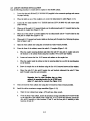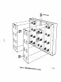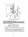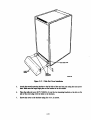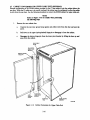
1
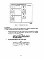
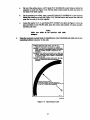
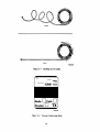
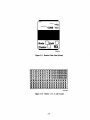
EK-SC008-UG-002
SC008 Star Coupler
User's Guide
Prepared by Educational Services
of
Digital EQuipment Corporation
Second Edition, May 1988
Copyright" 1988 by Digital Equipment Corporation
All Rights Reserved
The information in this document is subject to change without notice
and should not be construed as a commitment by Digital Equipment
Corporation. Digital Equipment Corporation assumes no responsibility
for any errors that may appear in this document.
Printed in U.S.A.
Notice: This equipment generates, u.s, and may emit radio frequency
energy. The equipment has been type tested and found to comply with
the Jimita for a Class B computing device pursuant to Subpart J of Part
15 of FCC Rules, which are designed to proQle reasonable protection
apinst such radio frequency interference when operated in a commercial environment. Operation of this equipment jn a residential area may
cause interference in which case the user at his own expeue may be IeqWred to take measures to correct the interference.
The following are trademarks of Digital Equipment Corporation:
DATATRIEVE
DEC
DEC mate
DECnet
DECset
DECsystem-lO
DECSYSTEM-20
DECtape
DEC US
DECwriter
DIBOL
MASSBUS
PDP
P/OS
Professional
Rainbow
RSI'S
RSX
UNIBUS
VAX
VMS
VT
Work Processor
CONTENTS
CHAPTER 1
INTRODUCTION
1.1
1.2
1.3
1.4
1.5
The Computer Interconnect .................................................................................. I-I
The Star Coupler .................................................................................................. 1-2
SCOO8 Option Variations ...................................................................................... 1-2
SCOO8 Specifications ........................................................................................ 1-3
Related I><>cuments .............................................................................................. 1-4
CHAPl'ER 1
INSfALLATION
2.1
2.2
2.3
2.4
2.5
2.6
2.7
2.S
Preinstallation Planning ........................................................................................ 2-1
UnJ)acking and InsJ)eCtion ..................................................................................... 2-1
Configuration ...................................................................................................... 2-3
Cabling ............................................................................................................ 2-6
Add-On Coupler Installation ............................................................................... 2-12
Cable Exit Cover Installation (Optional) .............................................................. 2-14
Cabinet Conversion for Upper Cable Exit (Optional) ............................................ 2-16
Updated Cable Managers ........................................................................................ 2 -IS
1-1
1-2
Four·Node CI Cl1lSter ....................................................................................... 1-1
sc008-AC Star Coupler ...................................................................................... 1-2
2-1
2-2
2-3
2-4
2-5
2-6
2-7
2-S
2-9
2-10
2-11
2-12
2-13
2-14
2-15
2-16
UnJ)acking the SCOOS-AC ................................................................................... 2-2
Ileskidding the SCOOS-AC Cabinet ................................................................ ~ ..... 2-3
SCOO8-AC Cabinet Internals (Rear View)............................................................. 2-4
SCOO8 Coupler Box I>etails ..................................•...•••.•..................................... 2-5
Configuration Path I..abel ..................................................................................... 2-5
Bend Radius I..abel ............................................................................................... 2-7
Unrolling the CI Cables ........................................................................................ 2-8
Tra.nsmit Cable I..abel (Red) .................................................................................. 2-8
Receive Cable I..abel (Green) .............................................................................. 2-9
Marker 1-15, A·and B I..abel ................................................................................ 2-9
Node Number I..a.bel (Node 3) ............................................................................ 2-10
sc008 Internal Cable Routing ......................................................................... 2-11
Labeling SCOOSs for Nodes 8 to 15, A and B ....................................................... 2-13
Mounting Node 8-15 Couplers ........................................................................... 2-14
Cable Exit Cover Installation .............................................................................. 2-1 5
Cabinet Conversion for Upper Cable Exit ............................................................ 2-16
Tables
1-1
1-2
SCOO8 Option Variations ................................................................................... 1-3
SCOO8 Specifications............................................................................................. 1-3
iii
CHAPTER 1
INTRODUCTION
1.1 THE COMPUTER INTERCONNECf
The Computer Interconnect (CI) is a high-speed, serial data bus that is used to link computer subsystems
(nodes) together to form a CI cluster. Typically, the cluster is confmed to a computer room environment.
Nodes may consist of CPUs, memory, and intelligent mass storage, communication, and data acquisition
subsystems. Features of the CI include:
•
Dual signal paths capable of simultaneous operation
•
70 megabit per second path bandwidth
•
Low error rates
•
Packet-oriented transmission
•
Immediate acknowledgment of the successful receipt of a packet
•
Contention arbitration at light loading and round-robin arbitration at heavy loading
A star distribution system is used to connect the nodes of a CI cluster. For each signal path, a pair of CI bus
cables (one for transmit, one for receive) connect each node's CI port interface to the central Star Coupler
for that path (Figure 1-1). The coupler receives and distributes bus signals transmitted by a node to the
other CI nodes along the same signal path.
T
T
R
NODE
STAR
COUPLER A
CI
PORT
T
R
NODE
1
rr=
T
R
I'
II
CI
PORT
NODE
R
STAR
COUPLER B
II
1
II
II
CI
PORT
T
R
CI
PORT
NODE
~T
T=-
R
R
TT8-OOO1·88
Figure 1-1 Four-Node CI Cluster
I-I
1.1 THE STAR COUPLER
The SCOO8 Star Coupler is one of the building blocks of the CI. It is a passive, RF-transfonner coupling
device that provides the central connection point for up to 16 nodes in a CI cluster. All nodes within the
cluster communicate directly via the Star Coupler. Features of the SCOO8 include:
•
High reliability -
No power or cooling requirements.
•
Individual node/coupler bus cables may be added or removed without affecting cluster
communications.
•
Failure of a node or its bus cables will not affect other cluster nodes.
•
Isolates signals, noise, and faults associated with a single node from the cluster.
•
Terminates node bus cables with their proper (SO-ohm) impedance.
1.3 SCOO8 0Pl10N VARIATIONS
The Star Coupler is designed in a modular way to allow for easy cluster expandability. The basic Star
Coupler box allows up to eight nodes (single path) to be connected together. Special modularity connectors
on each coupler box allow two couplers to be connected together for cluster expansion (up to 16 nodes).
Dual path CI clusters require a minimum of two Star Coupler boxes. Table 1-1 lists the available option
variations, and Figure 1-2 shows the SCOO8-AC Star Coupler.
•
REAR
FRONT
Figure 1-2 SCOO8-AC Star Coupler
1-2
Table 1-1 SCOO8 Option Variations
SCOO8-AC
aa.terSize
8 nodes; dual path
SCOO8-AD
16 nodes; dual path
Desigaation
Consists of:
Two Star Coupler boxes mounted in
a 40-inch (H9642 type) cabinet
Two add-on Star Coupler boxes (to
be added to an existing SCOO8-AC
configuration)
1.4 SCOO8 SPECIFICATIONS
The sc008 specifications are outlined in Table 1-2.
TaWe 1-2 SCOO8 SpeciflC8tioas
SpecifICation
Description
I/O connectors
Female TNC coaxial
Impedance
50 ohms
Bandwidth
1 to 100 Mhz
Isolation between I/O ports
30 db
Insertion loss (input to output)
20 db
Size
18" X 8.75" X 4"
(single coupler)
Weight
91bs. 11 oz.
(single coupler)
Mounting
19" rack mount with nonconductive
brackets
Environmental
MIL-STD-202E
Operating and storage
temperature range
-55OC to l000c
(-67°F to 212°F)
Operating humidity
95% maximum
1-3
1.5 RELATED DOCUMENTS
The following document is related to this guide:
Cl780 User's Guide (EK-CI7SO-UG)
DIGITAL personnel may order hardcopy documents from:
Digital Equipment Corporation
444 Whitney Street
Northboro, Massachusetts 01532
Attn: Publishing and Circulation Services (NR03/W3)
Order Processing Section
Customers may order hardcopy documents from:
Digital Equipment Corporation
Accessories and Supplies Group
Cotton Road
Nashua, New
03060
Ham.-mre
Forinfonnation,calll-SOD-257-1710.
Information concerning microfiche libraries may be obtained from:
Digital Equipment Corporation
Micropublishing Group (BUOjE46)
12 Crosby Drive
Bedford, Massachusetts 01730
1-4
CHAPTER 2
INSTALLATION
2.1 PREINSfALLATION PLANNING
Before installing the SCOO8, consideration should be given to its physical placement relative to the CI
nodes that will be connected to it. The coupler must be placed in a location that will allow the bus cables
from each node to reach it. Factors to consider when planning a location for the sc008 are:
1.
Maximum length of the CI bus cables that will be used to connect each node to the coupler.
2.
How the CI bus cables will be routed between the coupler and each node (Le., overhead, under
the floor, etc).
NOTE
Allow approximately six feet (two meters) of cable
Ieagth for routing inside the SCOO8 cabinet.
2.2 UNPACKING AND INSPECI'lON
The sc008-AC is packaged for shipment mounted on a shipping skid and covered with a cardboard container. The container is secured to the skid with two polyester straps. Unloading ramps are provided to aid
in removing the cabinet from the skid (Figure 2-1). .
1.
Check the container for external damage such as dents, holes, or crushed comers.
2.
Notify the customer of any damage and list it on the appropriate installation report form.
3.
Cut the two polyester shipping straps.
4.
Remove the container cover, two ramps, and the cardboard spacer.
S.
Lift up and remove the contaiDer tube and plastic bag.
NOTE
Allow ten feet (three meters) clearance from the rear
of the shipping skid when unloading the cabinet from
the skid (deskicldiag).
2-1
~ UFTAND
~ REMOVE
CONTAINER---~~
~
COVER
RAMPS _ _ _ _----4.-...,:
CONTAINER
TUBE
SCOO8
CABINET
PLASTIC
BAG
SHIPP~ING.=..-_ _~. .
SKID
POLYESTER
STRAPS
Figure 2-1 Unpacking the SCOOS-AC
6.
Attach the two ramps to the rear of the shipping skid by sliding the large end of each ramp into
the groove of the skid (Figure 2-2). Align the arrows on the skid with the arrows on the ramps.
7.
Use a 9/16-inch open-end wrench to unscrew and remove the four orange shipping brackets
located at the bottom of each corner of the cabinet (Figure 2-2).
S.
Remove the cabinet from the shipping skid by rolling it down the unloading ramps to the floor.
WARNING
EXTREME CARE SHOULD BE TAKEN! TIle
cabiIIet weighs ill excess of 200 poUIIds. At least two
people sIaoaId be preseat to assist ill desIdddiag tile
cabiaet.
9.
Open the rear door of the cabinet using a Sl32-inch Allen wrench and remove any accessory
cartons/packages located inside. An Allen wrench is provided in a plastic bag that is taped to the
outside of the cabinet.
10.
Open all cartons/packages and inventory their contents against the packing list.
II.
Inspect the cabinet and all components for damage such as scratches, dents, or breaks. Report
any damage to the customer and record it on the appropriate installation report form.
2-2
ORANGE
SHIPPING
BRACKETS
~ORANGE
SHIPPING BRACKETS
Figure 2-2 Deskidding the SCOO8-AC Cabinet
2.3 CONFIGURATION
The sc008 coupler box contains eight transmit ports (connectors), eight receive ports, and six modularity
connectors. The modularity connectors allow two coupler boxes to be cabled together as one 16-port unit.
A minimum of two sc008 couplers are required to configure a dual path CI cluster, one for data path A
nodes 0 to 7 and the o~cr for data path B nodes 0 to 7. ConfIgUre the SCOO8 for the number of nodes to be
connected using the following procedure.
NOTE
For some coafipratiolls of the SCOOI, Steps 1 and 2
wiD be performed at the factory. Cheek to see if the
data path B label Is already on the lower coupler box
as shoWil in Figure 2-3. Skip Steps 1 and 2 if the
label Is presea~
1.
Locate the data path B label supplied (PIN 3618845-02) and remove its paper backing.
2.
From the rear of the cabinet, place the label on the lower (data path B) coupler box so it covers
the silkscrecned A label (Figures 2-3 and 2-4).
3.
If more than eight nodes are to be connected, install the add-on couplers using the procedure in
Section 2.5.
2-3
~.• [51 ..
••. n~~.
••
•• n ••
CONFIGURATION
LABEL
~.. [5] ..
••• n[!]~
•••
•• n ••
BEND RADIUS
LABEL
TXlRXA
NOOE0-7
TXlRX8
NOOE0-7
Figure 2-3 sc008-AC Cabinet Internals (Rear View)
4.
Remove (unscrew) the terminators from the transmit and receive ports that wiD
cables connected (Figure 2-4).
"we a ...
NOTE
Te....ton MUsr he ~ to _ _ truImit ... receiYe ports to ...... tile correct tend_ttng Impedaace. UIIIISed . . . .rity eo_edors do
.. ....are temt.ators.
5.
Store terminators in the terminator storage assemblies located on the side of the rear cabiaet
frame (Figure 2-3).
6.
Connect the modularity cables supplied (PIN 7018530) to the correct modularity coaaecton
(Figures 2-4 and 2-5).
. a.
For an installation of eight nodes or less:
I)
Connect a cable between modularity connectors 1 and 4 on each data path coupler.
2)
Store extra cables on remaining modularity connectors, as shipped (Figure 2-4). This
will not affect operation.
2-4
b.
For an installation of nine nodes or more:
1)
Connect a cable between modularity connectors 1 and 2 on the node 0-7 coupler for
each data path.
2)
Connect a cable between modularity connectors 4 and 5 on the node 0-7 coupler for
each data path.
3)
Connect a cable between modularity connector 3 on the node 0-7 coupler to connector 1 on the node 8-15 coupler for each data path.
4)
Connect a cable between modularity connector 6 on the node 0-7 coupler to connector 4 on the node 8-15 coupler for each data path.
rF=::::::--__r~:l[]---Ji~
DATAPATHBLAIEL
UNTERMINATED
CONNECTOR
~"
Figure 2-4 sc008 Coupler Box Details
2-5
.
..
..
Configuration label Information Se008
A
8-Node/Single Path
A
0-7
0-7 0 0 0-7
o
A
0
8-Node/Dual Path
B
0-7
0-7 0 0 0-7
00
0-7
0-7
8-15 0 0 8-15
00
00
A
~~
A
0-7 0 0 0-7
B
16-NodelDual Path
16-Node/Singie Path
~~ 0-7
B
~~ 0-7
8-1500 8-15
00
~~
I I
A
-'-'
8-150 0 8-15
00
. . . . .·01
Figure 2-5 Configuration Path Label
%.4 CABUNG
In dual path CI clusters, a set of four CI bus cables (BNCIA-XX) is requiredror connectina each node to
the SCOOS. Use the following procedure to cable a CI node to the coupler.
1.
Carefully unroll and route the CI bus cables between the node and the SCOOS. Do not exceed the
4-inch bend radius (Figure 2-6) when bending the cables, and take care to avoid any kinb,
twists, or cuts in the cables (Figure 2-7).
CAUTION
Accidelatal grouadiag of ..y . .tal part of tile
BNClA cables to cabiaet (chassis) gn.d wiI .....
oaIy degrade perf. . .wce.
2.
Place identification labels on both ends of each CI cable.
NOTE
DO......,
Steps a ... b wiD
IJe perfonaed at tile factory. Verify that two of tile CI cables ha,e red TX
labels attached to ad eiid, and the .....Wng two
cables ha,e green RX labels 011 each end. Skip Steps
a and b if the labels are present.
2-6
a.
On two of the cables, place a red TX label (PIN 3618808-02) a short distance behind the
CODDeCtor on each end (Figure 2-8). Fold the label in half around the cable and press the
two ends of the label together.
b.
On the remaining two cables, place a green RX label (PIN 3618808-01) a short distance
behind the connector on each end (Figure 2-9). Fold the label in half around the cable and
press the two ends of the label together.
c.
Locate the marker 0-15, A and B label (PIN 3618807-01) shown in Figure 2-10. In the
space provided on each TX/RX label, place the correct node number, CI cluster number,
and data path letter.
NOTE
Make sure labels do IIOt i.terrere with cable
...agers.
3.
Usias the previously attached labels fQl'identification, screw (clockwise) each cable onto its corresponding bulkhead connector on the node.
Caution: Cable bend radii critical. use full Size
minimum bend shown here below as a guide.
Attention: Les rayons de courbure des clbles sont
d'une importance essentiele. Employer Ia courbure
minimale complete rnontrie ci-dessous i titre
d'exemp!e.
PNcauciOn: Los radios de curvatura de los cables son
crfticos. Doble los cables hasta tener pOr completo
Ja.curvaturaminima Que. sa indica a continuaci6n
a manera de gUa
Yoraicht! Kabelbiegungsradien sind kritisch. Die volle,
unten als Leitauge gezeigte MiniimalbieglUnQ
benutzen.
I~_~
Cour.bur. minima'.: 4 pouces (10.16 em.)
La eurvatura n1f'nlma .. de 4 pulged.. (10.16 em.)
10.16 em. (4 Inch..) Minlmalblegung.
~
TT8-0008-88
Figure 2-6 Bend Radius Label
2-7
RIGHT
Figure 2-7 Unrolling the CI Cables
lO""K
Node
-
·J\a~
-I~NB
:N/d
DPath D
Cluster
D
TX
Figure 2-8 Transmit Cable Label (Red)
2-8
Node DPath
Cluster
D
D RX
TTB-0011-18
Figure 2~9
0
0
0
0
A
1
1
1
1
A
A A
BB
BB
2 3 4 5
2 3 4 5
2 3 4 5
2 3 4 5
~eceive
8
8
8
6
7
7
7
7
Cable ~bel (Green)
8
8
8
8
A A A A A A A
A A AAAAA
BB B BBBB
B BB B B BB
9 10 11 12 ~: ~4 ~5
9 10 11 12 1: 14 15
9 10 11 12ff: 14 15
9 10 11 12~3 ~4 15
A A AAAAA
A AA AAAA
B B B B BB B
B BBB BBB
T'T8-0012-18
Figure 2-10 Marker 1-15, A and B Label
2-9
4.
Check the rear door of the node cabinet that houses the CI interface for a node number label
(Figure 2-11). If no label is attached, locate the applicable label (PIN 3619264-17) and place
the correct numbered label, at eye level, on the outside of the door.
NOTE
Refer to the Cl780 User's Guide (or appropriate)
for information on assignment of node numbers.
5.
Connect the CI bus cables to the SCOO8 coupler (Figure 2-12). Do not exceed the 4-inch bend
radius (Figure 2-6) when bending the cables, and take care to avoid any kinks, twists, or cuts in
the cables.
a.
Using the attached labels for identification, screw each cable onto its correspmding SCOO8
port (i.e., node 0 TX A cable connects to the data path A coupler transmit 0 port).
b.
Route the cables down through the side cable guides with node 0-7 cables on the left side and
node 8-15 cables on the right side. Follow the cabling sequence of front to· rear for nodes
o to 7 and nodes 8 to 15, respectively.
c.
Route the cables through the cabinet from the side managers (through the rear cable guide).
Follow the cabling sequence of left to right for nodes 0 to 1S, respectively.
TIC_,a
Figure 2-11 Node Number Label (Node 3)
2-10
Figure 2-12 SCOO8 Internal Cable Routing
2-11
1.5 ADD-ON COUPLER INSTALLATION
Use the following procedure to install add-on couplers in the SCOO8 cabinet.
1.
Locate the data path B label (PIN 3618845-02) supplied in the accessories package and remove
its paper backing.
2.
Place the label on one of the couplers so it covers the silkscreened A label (Figure 2-13).
3.
Locate the two nodes number 8-15 TX/RX label sets (PIN 3618845-01) and remove their
paper backing.
4.
Place one of the node 8-15 transmit labels over the silkscreened node 0-7 transmit label on the
data path A coupler box (Figure 2-13).
5.
Place one of the node 8-15 receive labels over the silkscreened node 0-7 receive label on the
data path A coupler box (Figure 2-13).
6.
Place node 8-15 transmit and receive labels on the data path B coupler box, fonowing the pr0cedure in Steps 4 and 5.
7.
Open the front cabinet door using the 5/32-inch hex Allen wrench provided.
8.
From the front of the cabinet, mount the node 8-15 couplers (Figure 2-14).
a.
Place the coupler mounting brackets right below the node 0-7 data path A coupler and screw
the brackets to the cabinet frame using four machine 10-32 screws and washers.
b.
Loosen and remove the four 10-32 screws and washers 00 the coupler box.
c.
Place the coupler inside the cabinet so that its mounting holes line up with the matching slots
on the brackets.
d.
Screw the coupler box to the brackets using the four 10-32 removed screws and the washers.
e.
Mount the node 8-15 data path B coupler box and brackets underneath the node 0-7 data
path B coupler using the same procedure.
NOTE
Remember 'that for those machines tIIat are being
updated, the mounting brackets for the SCOO8 boxes,
nodes 0-7, must also be re.ened. (See Figure 1-14.)
9.
10.
Close and lock the front cabinet door using the 5/32-inch hex Allen wrench provided.
Install the add-on terminator storage assemblies (Figure 2-12).
a.
Open the rear cabinet door using a 5/32-inch hex Allen wrench.
b.
From the back of the cabinet, mount the terminator storage assemblies (PIN 7018770-00)
to the right side of the cabinet frame. Using four 10 X 32 screws per assembly, secure the
data path B assembly at hole locations 12 and 21 and the data path A assembly at hole
locations 40 and 49.
2-12
~TA'A1lt8LA11£L
,
- - --- --- TRANSMIT
NODE 8-11
-- --- ---
,
- --
LA8eL
..--
- -- ...--
REceIVE
NODE ..
--------
LABEL
FtgUrc 2-13 SCOos Labeling for Nodes 8 to IS, A and B
-
TX/RXI
NODE8-'S
FRONT
Figure 2-14 Mounting Node 8-15 Couplers
2.6 CABLE EXIT COVER INSfALLATION (OPTIONAL)
A cable exit cover is provided with the sc008-AC for use in those installations where the CI bus cables are
to be routed under the floor. The cover serves as a safety feature by providing an enclosure over the floor
opening at the point where the CI cables exit the sc008 cabinet and enter the floor opening. Use the
following procedure to install the cable exit cover.
NOTE
Refer to Figure 2-15 for details wllea perfOl'llliag
Steps 2 to 7.
l.
Locate the two cable cover mounting brackets (PIN 7426225-1).
2.
Remove and save the two lA-inch X 20-inch screws holding the right side of the rear base trim to
the cabinet.
3.
Place one of the mounting brackets over the trim with the large angle plate toward the outside.
Position the bracket so its two large holes are aligned with the screw holes in the trim.
4.
Screw the bracket and the rear base trim to the cabinet with the two screws removed in Step 2.
2-14
~~Ht--~~~REAR BASE TRIM
Figure 2-1 S Cable Exit Cover InstaiIation
S.
Attach the second mounting bracket to the left side of the rear base trim using the same procedure. Make sure the large angle plate on the bracket is on the outside.
6.
Place the cable exit cover (PIN 7426224-1) over the two mounting brackets so the slots on the
side of the cover a1ign with the holes in the brackets.
7.
Screws the cover to the brackets using four 10 X 32 screws.
2-15
2.7 CABINET CONVERSION FOR UPPER CABLE EXIT (OPTIONAL)
Normal configuration of the seoos cabinet provides for the CI bus cables to exit the cabinet below the
rear door. When the CI cables are to be routed overhead, the cabinet may be configured to allow the cables
to exit above the rear door. Use the following procedure to convert the SCOO8 cabinet for upper cable exit.
NOTE
Refer to Figure 2-16 for details whea performiag
the following steps.
1.
Remove the rear cabinet door.
a.
Unscrew the rear door ground strap (green and yellow wire) from the door and save the
screw.
b.
Pull down on the upper (spring-loaded) binge-pin to disengage it from the cabinet.
c.
Disengage the bottom hinge-pin from the lower pivot bracket by lifting· the door up and
away from the cabinet.
SPRING LOADED
HINGE·PIN
I
l--/
REAR DOOR
LOWER PIVOT
BRACKET
TTB-OO, ....
Figure 2-16 Cabinet Conversion for Upper Cable Exit
2-16
2.
3.
Remove the lower pivot bracket by unscrewing the two screws holding it to the cabinet. Save
these two screws.
Mount the pivot bracket supplied in the accessories package (PIN 7422272-01) to the upper
part of the rear cabinet frame (holes 51 and 54). Use the two screws saved in Step 2.
4.
Remove the rear cable guide from the lower part of the cabinet by unscrewing the four screws
(two on each side) holding it to the frame. Save these four screws.
5.
Mount the rear cable guide above the newly installed pivot bracket (holes 56 and 57) using the
four screws saved in Step 4.
6.
Loosen the two lA X 20 screws holding the right side of the rear base trim to the cabinet.
7.
Mount the lower pivot bracket supplied in the accessories package (PIN 7422221-(0) to the
rear base trim by placing the bracket cutouts over the two loosened screws and tightening the
screws.
8.
9.
10.
Lower the rear door locking assembly.
a.
Remove and save the two screws holding the locking assembly to the cabinet.
b.
Mount the locking assembly on the cabinet at hole locations 28 and 30 using the previously
removed screws.
Mount the rear door on the cabinet.
a.
Engage the bottom binge-pin into the lower pivot bracket.
b.
Pull down on the upper (spring-loaded) binge-pin and engage it into the upper pivot
bracket.
c.
Attach the ground strap to the door using the screw saved in Step la.
d
Check to see that the door lock aligns with the cabinet locking assembly, allowing the door
to be locked. Perform Step 10 if alignment is necessary.
A1i8ll the rear door locking assembly (optional).
a.
Open the front door and remove the right side panel locking bracket.
b.
Remove the right side panel.
c.
Loosen the two screws on the side of the rear door locking assembly.
d.
Close and lock the rear door.
e.
Tighten the two loose locking assembly screws.
f.
Reinstall the side panel and its locking bracket.
g.
Close and lock the front door.
2-17
2.8 UPDATED CABLE MANAGERS
New side cable managers (PIN 74-37051-01) and a new rear cable manager (PIN 74-37052-01) are
available.
These managers may be used to replace current side managers with the PIN of 74-25765-00 and a rear
manager with the PIN of 74-25764-00. For those ordering the SCOO8-AD and currently using the ahem:
managers (74-25765-00 and 74-25764-00), it is recommended to order the new parts.
To install the new managers:
For the side manager 1.
2.
3.
Loosen and remove all three 10-32 screws.
Remove the current side cable manaser.
Place the new manager in the same place using the J'eIIlOVedscrews and tighten.
For the rear manager 1.
2.
3.
Loosen and remove all four 10-32 screws.
Remove the current rear manager.
Place the new manager in the same place and tighten using the J'eIIlOVed screws.
NOTE
It is also ............. that witll tIIeae DeW - .......
the IDOUDtlag Inckets for tile SCOO8 IMmel ......
reYersecl. (See Sectiaa 2.5.)
2-t8
sc008 STAR COUPLER
USER'S GUIDE
Aeade"s Comments
Your comments and suggestions will help us In our continuous effort to Improve the quality and
usefulne.. of our publication..
What is your general reaction to this manual? In your judgment is it complete. accurate. well organized, well
written, etc? Is it easy to use? _ _ _ _ _ _ _ _ _ _ _ _ _ _ _ _ _ _ _ _ _ _ _ __
What features are most useful?_ _ _ _ _ _ _ _ _ _ _ _ _ _ _ _ _ _ _ _ _ _ _ __
What faults or errors have you found in the manual?_ _ _ _ _ _ _ _ _ _ _ _ _ _ _ _ __
Does this manual satiSfy the need you think it was intended to satisfy?_ _ _ _ _ _ _ _ _ _ __
Does it satisfy your needs?_ _ _ _ _ _ _ _ Wh'(l _ _ _ _ _ _ _ _ _ _ _ _ _ _ __
Please send me the current copy of the Document.tlon Product. Directory, which contains information
on the remainder of DIGITAL-. technical documentation.
Name,-----________________ StnNrt______________________________
ntle
City_ _ _ _ _ _ _ _ _ _ _ _ _ __
Company
Department
StatelCOUntfy _ _ _ _ _ _ _ _ _ _ __
Zip _ _ _ _ _ _ _ _ _ _ _ _ _ _ __
Additional copies of this document are aYaiiable from:
Digital Equipment Corporation
Accessories and Supplies Group
P.O. Box CS2008
Nashua. New Hampshire 03061
Attention: Documentation Products
Telephone: 1-800-258-1710
Order Nou.-__
E_K_-S_C_OOS_-_U_G_-OO_2_ _ _ __
vwo
---------------------~~-------------------~.,
_ _ _ _ _ _ _ _ _ _ _ _ _ _ _ _ _ 00 NotT. . - Fold .............
---------------..1..
I
I
III II I
No Po.tag.
N.c...."
if Melled In the
Unlt.d Shit••
BUSINESS REPLY MAIL
FIRST CLASS
PERMIT NO. 33
MAYNARD, MA.
POSTAGE WILL BE PAID BY ADDRESSEE
Digital Equipment Corporation
Educational Services / Quality Assurance
12 Crosby Drive, BUO/E08
Bedford, MA 01730