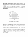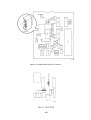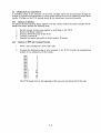
1
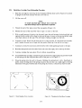
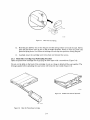
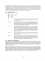
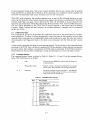
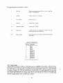
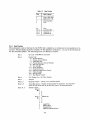
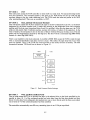
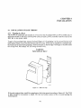
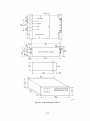
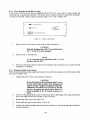
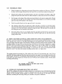
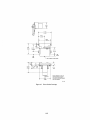
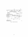
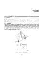
EK-OTU58-UG-001
TU58 DECtape II
User's Guide
digital equipment corporation • maynard, massachusetts
1st Editi on, October 1978
The drawings and specifications herein are the property of Digital Equipment
Corporation and shall not be reproduced or copied or used in whole or in part
as the basis for the manufacture or sale of equipment described herein without
written permission.
Copyright
©
1978 by Digital Equipment Corporation
The material in this manual is for informational
purposes and is subject to change without notice.
Digital Equipment Corporation assumes no responsibility for any errors which may appear in
this man ual.
Printed in U.S.A.
This document was set on DIGITAL's DECset-SOOO
computerized typesetting system.
The following are trademarks of Digital Equipment Corporation,
Maynard, Massachusetts:
DIGITAL
DEC
PDP
DECUS
UNIBUS
DECsystem-lO
DECSYSTEM-20
DIBOL
EDUSYSTEM
VAX
VMS
MASSBUS
OMNIBUS
OS/8
RSTS
RSX
lAS
CONTENTS
CHAPTER 1
INTRODUCTION
l.1
l.2
l.3
l.3.1
1.3.2
1.4
1.4.1
1.4.2
1.4.3
l.4.4
l.S
l.6
SCOPE ................................................................................................................ 1-1
GENERAL DESCRIPTION ............................................................................... 1-1
BLOCK DIAGRAM ........................................................................................... 1-3
Drive Control ............................................................................................... 1-4
Processor ...................................................................................................... 1-4
SPECIFICATIONS ............................................................................................. 1-4
Performance ................................................................................................. 1-4
Electrical ...................................................................................................... 1- S
Mechanical ................................................................................................... I-S
Environmental ............................................................................................. 1-S
CONFIG URATIONS ......................................................................................... 1-6
HARDWARE DOCUMENTATION ORDERING INFORMATION .............. 1-7
CHAPTER 2
OPERATION
2,,1
2.l.1
2.l.2
2.1.3
2.2
2.2.l
2.3
2.3.1
2.3.2
2.3.3
2.3.4
2.3.5
2.4
2.4.1
2.4.2
2.4.3
2.S
2.S.1
2.S.2
2.S.2.1
2.S.2.2
2.S.2.3
TUS8-CA RACKMOUNTCONTROLS AND INDICATORS .......................... 2-1
Front Panel .................................................................................................. 2-1
Run Indicator ............................................................................................... 2-1
Application and Removal of Power .............................................................. 2- t
TUS8 COMPONENTS CONTROLS AND INDICATORS ................................ 2-2
Application and Removal of Power .............................................................. 2-2
CARTRIDGE ..................................................................................................... 2-2
Cartridge Loading ........................................................................................ 2-2
Cartridge Unloading ......................................................... ,......................... 1-3
Keeping Track of Cartridges ......................................................................... 2-3
Write Protect Tab ......................................................................................... 2-J
Cartridge Storage and Care .......................................................................... 2-3
MAINTENANCE ...............................................................................................2-4
Head and Puck Cleaning .............................................................................. 2-4
Operator 1~rouble Isolation ........................................................................... 2-4
Cartridge Wear ............................................................................................ 2-S
CARTRIDGE REPAIR ......................................................................................2-5
Metal-Base Cartridge Tape Rethreading Procedure ..................................... .2-6
Plastic-Base Cartridge Tape Rethreading Procedure ..................................... 2-7
Preparation for Threading ................................................................... 2-8
Threading the Cartridge ....................................................................... 2-8
Closing the Cartridge ............................................................................ 2-9
CHAPTER 3
PROGRAMMING
3.1
3.1.1
3.1.2
GENERAL PRINCIPLES .................................................................................. 3-1
Block Number, Byte Count, and Drive Number .......................................... .3-1
Special Handler Functions ............................................................................ 3-1
iii
CONTENTS (Cont)
Page
3.2
3.2.1
3.2.2
3.2.3
3.3
3.3.1
3.3.2
3.3.3
3.4
RADIAL SERIAL PROTOCOL (RSP) .............................................................. .3-1
Message Packets ........................................................................................... 3-1
Flag Byte Op Codes ...................................................................................... 3-2
Signal (Break) and Initialization ................................................................... 3-2
COMMAND SET ............................................................................................... 3-3
Command Packets ........................................................................................ 3-3
Data Packets ................................................................................................ 3-4
End Packets .................................................................................................. 3-5
THE INSTRUCTION SET ................................................................................. 3-6
CHAPTER 4
INSTALLATION
4.1
4.1.1
4.1.2
4.1.3
4.1.4
4.2
4.3
4.3.1
4.3.2
4.4
4.4.1
4.4.2
INSTALLATION OF RACK VERSION ............................................................4-1
Mounting in a Rack ...................................................................................... 4-1
Power Selection for the Rack Version ........................................................... 4-3
Removing Module From Chassis ................................................................. .4-3
Reinstalling the Module .............................................................................. .4-5
DRIVE AND MODULE INSTALLATION (DOES NOT
APPLY TO RACKMOUNT) ..............................................................................4-5
INTERFACE STANDARDS SELECTION AND SETUP ................................ .4-5
Selecting Interface Standards ....................................................................... .4-8
Connecting Standards Jumpers .................................................................... .4-9
OPERATIONAL CHECKOUT ........................................................................ 4-11
Checkout of Interface ................................................................................. 4-11
Checkout of RSP and Command Function ................................................ .4-11
CHAPTER 5
OPTIONS
5.1
5.1.1
5.2
RUN INDICA TOR ............................................................................................. 5-1
Installation ................................................................................................... 5-1
BOOT SWITCH .................................................................................................. 5-2
FIGURES
Figure No.
1-1
1-2
1-3
1-4
1-5
Title
Page
Tape Cartridge Partially Inserted into Drive (Top View) ....................................... 1-2
An Exchange in Radial Serial Protocol ................................................................ .1- 3
TU58 Block Diagram ........................................................................................... 1-3
Single Record on Tape ........................................................................................ .1-5
Block Locations on Tape ...................................................................................... 1-5
iv
FIGURES (Coot)
Figure No.
2-1
2-2
2-3
2-4
2-5
2-6
2-7
2-8
2-9
2-10
2-11
3-1
3-2
4-1
4-2
4-3
4-4
4-5
4-6
4-7
4-8
4-9
5-1
Title
Page
TU58-CA Rackmount Front Panel ..................................................................... .2-1
Loading a Cartridge ............................................................................................. 2- 2
Write Protect Tab ................................................................................................. 2-3
View Into Tape Drive Cartridge Slot ................................................................... .2-4
Metal Baseplate Screw Locations ......................................................................... 2-6
Threading the Metal- Base Cartridge ..................................................................... 2-6
Head Gate and Spring .......................................................................................... 2-7
Open the Plastic-Base Cartridge ........................................................................... 2- 7
Welded Case Halves Separated ............................................................................. 2-7
Stretch the Belt with the Floating Roller ............................................................... 2-8
Threading the Plastic-Base Cartridge .................................................................... 2-8
Read Command Packet Exchange ........................................................................ 3-7
Write Command Packet Exchange ....................................................................... 3-8
Bezel and Clip ...................................................................................................... 4-1
Rack Mounting the TU58-CA ............................................................................. .4-2
TU 58-CA Rear Panel ........................................................................................... 4-3
Module Removed from Chassis ............................................................................4-4
Drive Outline Drawings .......................................................................................4-6
Module Outline Drawing .....................................................................................4- 7
Data Rate and Cable Length for RS-423 .............................................................. .4-9
Interface Selection Jumper Pin Locations .......................................................... .4-1 0
Factory Wiring ................................................................................................... 4-10
Installation of Run Indicator ................................................................................ 5-1
TABLES
Table No.
2-1
3-1
3-2
3-3
3-4
4-1
Title
Page
Operator Trouble Isolation .................................................................................. 2-4
Command Packet Structure .................................................................................. 3-3
Instruction Set ...................................................................................................... 3-4
Data Packets ........................................................................................................ 3-5
End Packet ........................................................................................................... 3-6
TU 58 Module Connections ..................................................................................4-8
v
CHAPTER 1
INTRODUCTION
1.1 SCOPE
The TU58 DECtape II is a low-cost, mass-storage device which may be used in a wide variety of
applications. This manual provides the information that a user needs to install, interface, and command the operation of the tape system. (For information about the operation of the TU58 under DEC
operating systems, refer to the individual system manuals.)
Chapter 1 provides a general description of the TU58 and a list of its specifications including electrical
and mechanical requirements. The configurations section describes the different variations of the
TU58 that are available.
Chapter 2, the system operator's reference section, contains important information for day-to-day
operation and routine maintenance.
Chapter 3 is the programmer's guide. It contains functional descriptions of the TU58 command set,
illustrates command sequences, explains the details of the Radial Serial Protocol, and lists the system
instruction codes and byte sequences.
Chapter 4 gives illustrated instructions for jumper selection; mechanical, electrical, and interface installation; and operational checkout of the tape system.
Chapter 5 has details about the optional features available in the TU58.
1.2 GENERAL DESCRIPTION
The TU58 is a random-access, fixed-length-block, mass-storage tape system. It uses preformatted tape
cartridges which store 262 kilobytes of data in 512-byte blocks. There are 256 blocks on each of two
tracks. They may be accessed by a program in a fashion similar to data stored on disks or DECtape,
using a new, high-level instruction set. A file-oriented structure is easily implemented in an operating
system by setting aside several blocks on the tape to store a directory.
The TU58 is compact and mechanically simple. The tape cartridges are DIGIT AL-preformatted miniature reel-to-reel packages containing 42.7 m (140 ft) of 3.81 mm (0.150 in) wide tape. The tape is
driven by a single puck which engages a roller which moves an elastomer drive belt in the cartridge.
This belt loops around both tape spools and provides uniform tension and spill-free winding without
mechanical linkages (Figure 1-1). The simple single-point drive mechanism allows high reliability for
the entire system.
The control and drive circuitry of the TU58 is located on a single circuit board. The controller uses a
microprocessor (JLP) to reduce the tape handling and communications management load on the host
system.
1-1
DRIVE PUCK
HEAD
SWINGOUT
GATE
WRITE PROJECT
TAB
DRIVE
ROLLER
TAPE
TAPE
CARTRIDGE
Figure 1-1
ELASTOMER
BELT
Tape Cartridge Partially Inserted into Drive
(Top View)
The motor and tape head control, driver, and switching circuits to manage two tape drives are on the
printed circuit board with the JLP. The controller supports one or two drives, but only one drive can
operate at a time. The JLP controls all of the activities of the TU 58. Head and motor selection, speed
and direction changes, etc., are managed by outputs from I/O ports on a peripheral IC. The mechanical actions of the drives themselves are supervised by the JLP to improve the system's performance.
Operational amplifiers, comparators, and logic circuits perform amplification, signal switching and
conditioning, proportional control, and logic steering functions in the controller. The tape is protected
by motor current limiting and an anti-runaway timer.
Because of the JLP intelligence, requests from the host for data retrieval or storage need only contain
simple specifications about the transfer. The controller positions the tape and performs the transfer
without supervision from the host.
The host and controller communicate in a format called Radial Serial Protocol (RSP). The RSP uses
two kinds of byte sequences called message packets. Both command and data packets have protocol
information placed in specific locations in the byte sequence. This format is easily generated by the
TU58, making host-peripheral interaction possible at a high level with low cost.
Figure 1-2 illustrates a typical RSP exchange between a host computer and the TU58. Refer to Chapter
3 for a full discussion of RSP implementation.
The serial host interface operates on full-duplex, asynchronous 4-wire lines at jumper-selectable rates
from 150 to 38.4 kilobaud. The send and receive rates may be independently set with jumpers to
operate in accordance with Electronic Industries Association (EIA) Standards RS-422 or RS-423.
When set to RS-423, the TU58 is also compatible with devices complying with RS-232-C.
1-2
HOST
COMMAND
PACKET
~
DATA
PACKET
•
DATA
PACKET
I
I
II
I
I
II
I
II
I
Figure 1-2
TU58
CONTINUE
•
CONTINUE
MA-23B4
An Exchange in Radial Serial Protocol
1.3 BLOCK DIAGRAM
Figure 1-3 illustrates the structure of the TUS8 system. The data path is along the top of the diagram,
passing to the host through the processor at the right. The drive control is at the lower left, also closely
associated with the processor through the I/0 ports. The ports, memory, and universal asynchronous
receiver-transmitter (UART) are tied to the processor by an 8-bit-wide data/address bus.
TO HOST
MA-2378
Figure 1-3
TU58 Block Diagram
1-3
1.3.1 Drive Control
The cartridge drive motors are powered by servo-regulated speed and direction circuits. These are
controlled by the processor which monitors with tachometers and with signals from the tape. The
heads are selected by processor-controlled switches and either feed the automatic-gain-controlled
(AGe) read amplifier and decoder circuits or are driven by write currents encoded by the processor.
1.3.2 Processor
The processor consists of an 8085 processor supported by firmware in a 2-kilobyte read-only memory
(ROM) and by scratchpad and data buffer memory in a 256-byte random access memory (RAM). The
processor communicates with the drive control circuitry through a bidirectional IjOport. The UART
exchanges data between the TU58 processor bus and the host computer via the serial line drivers and
receivers.
1.4
SPECIFICATIONS
1.4.1
Performance
Capacity per cartridge
262,144 bytes, formatted in 512 blocks of 512 bytes each
Data transfer rate
Read/write on tape
Data buffer to interface
Cartridge life
41.7 Ils/data bit, 24 kbytes/s
150 to 38.4 kbaud, jumper selected
5000 minimum end-to-end tape passes
Data reliability
Hard error rate
1 in 107 bits read (before self-correction)
1 in 109 bits read (unrecoverable within 8 automatic retries)
Hard error rate with writeverify and system correction
2 in 1011 bits read/written
Error checking
Checksum with rotation
Soft data error rate
A verage access time
9.3 seconds
Maximum access time
28 seconds
Read/write tape speed
76 cm/s (30 in/s)
Search tape speed
152 cm/s (60 in/s)
Bit density
315 bits/cm (800 bits/in)
Flux reversal density
945 fr/cm (2400 fr/in)
Recording method
Ratio encoding
Medium
DECtape II cartridge with 42.7 m (140 ft) of 3.81 mm
(0.150 in) tape
Size: 6.1 X 8.1 X 1.3 cm (2.4 X 3.2 X 0.5 in)
Order TU58-K
NOTE
DECtape II is a preformatted version of the 3M DClOOA
or equivalent.
Track format (Figures 1-4 and
1-5)
Two tracks, each containing 1024 individually numbered, firmware-interleaved "records." Firmware manipulates 4 records at each operation to form 512-byte
blocks.
Drive
Single motor, head integrally cast into molded chassis
Drives per controller
1 or 2. Only one may operate at a time.
1-4
L -___________
78.7 b/cm
200 b/in ,-
315 b/Cm _ _ _ _ _ _ _ _ _ _ _ _ _ _ _...,.1
800 b/in
1
INTER
RECORD
MARK
I
HEADER
SYNC.
RECORD
NUMBER
I
TRK1
000 ... 01
TRKO
000 ... 01
N
+ 1024
N
COMPl
OF RCD.
NUMBER
I
DATA SYNC.
DATA SPACE
128 BYTES
CHECK
SUM
I
--N + 1024
00000000 .... 01
N
00000000 ... 01
END
SPACE
ALL ZEROS
TU58 ARRANGES FOUR
RECORDS AS ONE BLOCK
MA·2371
Figure 1-4
Single Record on Tape
\
\
)BOT
# 128
#384
# 129
# 385
# 130
# 386
# 131)
BOT
#0
# 256
#1
# 257
#2
# 258
#3(
(
I
#254
#126
#510
#255
#511
#382
#127
#383
EOT
MA·2373
Figure 1-5
1.4.2
Block Locations on Tape
Electrical
Power consmption
Module and 1 or 2 drives
11 W, typical, drive running
+5 V ±5% at 0.75 A, maximum
+ 12 V + 10% -5% at 1.2 A, peak
0.6 A average running
O.l A idle
These voltages need not stabilize simultaneously upon
power-on.
Rackmount
Serial interface standards
90-128, 180-256 Vac, 47-63 Hz, 35 W maximum
In accordance with RS-422 or RS-423; compatible with
RS-232-C
1.4.3 Mechanical
Drive
8.1 H X 8.3 D X 10.6 W cm (3.2 X 3.3 X 4.1 in) with 19
cm (7.5 in) cable
Board (Module)
l3.2 H X 26.5 D X 3.5 W cm (5.19 X 10.44 X 1.4 in)
Rackmount cabinet
l3.2 H X 38.l D X 48.3 W cm (5.l9 X 15.0 X 19.0 in)
Power connector to module
AMP 87159-6 with 87027-3 contacts (DEC part nos. 1212202-09, 12-12203-00)
Power connector to rackmount
European IEC standard
Interface connector to module
AMP 87133-5 with 87124-1 locking clip contacts and
87179-1 index pin (DEC part nos. 12-14268-02, 1214267-00, 12-15418-00)
1.4.4 Environmental
The TU58 meets the following environmental specifications. When the TU58-AB or -BB (Paragraph
1.5) is integrated in a host device such as a terminal, convection provides adequate cooling if the
interior temperature is below 50 0 C (122 0 F) dry bulb, 26 0 C (79 0 F) wet bulb.
1-5
Maximum dissipation
TU58-CA
TU58-AB. TU58-BB
120 Btu/hour
34 Btu/hour
Temperature
TU58-CA operating
15° C (59° F) to 32° C (90° F) ambient
TU58-CA nonoperating
_34° C (-30° F) to 60° C (140° F)
Medium operating temperature
0° C (32° F) to 50° C (122° F)
Maximum temperature difference between system ambient
and TU58 module
18° C (32.4° F)
Relative Humidity, non-condensing
TU58 operating
Maximum wet bulb
Minimum dew point
Relative humidity
26° C (79° F)
2° C (36° F)
20% to 80%
TU58 nonoperating
5% to 98%
Medium nonoperating
10% to 80%
CAUTION
If a cartridge has been exposed to either the maximum or
minimum temperature extreme, the tape should be
rewound one complete cycle before using (Paragraph
2.3.5). This is done to bring the tape to the proper tension.
1.5 CONFlGURATIONS
The TU58 is available in the following configurations with accompanying designations.
Components
TU58-AB
TU58-BB
Serial interface controller mod ule, surface mounting, with one drive.
Serial interface controller module, surface mounting, with two drives.
Subsystems
TU58-CA
Rackmount, two drives, serial interface controller module, power supply 110/220 V
switch-selectable, detachable line cord and fuses for 110 V, two cartridges.
NOTE
Order interface cable separately.
Additional Supplies
BC20Y-25 interface cable TU58 to DL-ll and DLV-ll, 7.5 m (25 ft)(1O-pin-to-40-pin connector)
BC20Z-25 interface cable TU58 to DLV-IIJ, 7.5 m (25 ft) (lO-pin-to-lO-pin connector)
TU58-K preformated tape cartridges. Available singly or in packs of five.
TUC-Ol Tape Drive Cleaning Kit
1-6
1.6 HARDWARE DOCUMENTATION ORDERING INFORMATION
The following TU58 DECtape II Tape Subsystem hardware manuals can be purchased from
DIGITAL's Accessory and Supplies Group.
Part No.
Title
EK-OTU58-UG-OOl
EK-OTU58-PS-OOl
EK-OTU58-TM-OOl
TU58 Tape Subsystem User's Guide (paper)
TU58 Tape Subsystem Pocket Service Guide (card)
TU58 Tape Subsystem Technical Manual (microfiche)
All purchase orders for hardware manuals should be forwarded to:
Digital Equipment Corporation
Cotton Road
Nashua, New Hampshire 03060
Accessory and Supplies Group (P086)
Purchase orders must show shipping and billing addresses and state whether a partial shipment will be
accepted. All correspondence and invoicing inquiries should be directed to the above address or call
toll-free 1-800-258-1710 in the continental U.S. only.
1-7
CHAPTER 2
OPERATION
2.1
TU58-CA RACKMOUNT CONTROlS AND INDICATORS
2.1.1 Front Panel
The front panel (Figure 2-1) has two slots for the tape cartridges and two tape motion indicator lights
for the drives. In addition, the decorative bezel has a small compartment that can be used to store up to
six cartridges in their boxes.
AREA
Figure 2-1
MA~~1
TU58-CA Rackmount Front Pane!
2.1.2 Run Indicator
Each tape drive has an LED that lights to indicate tape motion. Since data loss can occur if a cartridge
is removed while the tape is being written, the cartridge should not be removed if the light is on.
2.1.3 Application and Removal of Power
The TU58-CA does not have a power switch. If an outlet is available on a system power controller, the
TU58 may be plugged into the controller. Otherwise, it does not need to be turned off. Its idling power
consumption is less than 20 W.
When power is applied, the TU58 initializes itself, performs its internal diagnostic tests, and then asks
the host for an acknowledgement before it settles down to wait for instructions. Refer to Paragraph
3.2.3 for a description of the required exchange.
If power is removed while a tape is being written, data may be lost. There are no other restrictions on
power removal.
2-1
2.2 TU58 COMPONENTS CONTROLS AND INDICA TORS
Refer to the options section (Chapter 5) for installation and operation of OEM features.
2.2.1 Application and Removal of Power
The TU58 may be supplied with power from a host system. It is ready for operation within 1 second of
voltage stabilization. It does not need to be turned off when not in use; its idling power consumption is
less than 5 W.
When power is applied, the TU58 initializes itself, performs its internal diagnostic tests, and then asks
the host for an acknowldgement before it settles down to wait for instructions. Refer to Paragraph
3.2.3 for a description of the required exchange.
If power is removed while a tape is being written, data may be lost. There are no other restrictions on
power removal.
2.3
CARTRIDGE
2.3.1 Cartridge Loading
The TU58 drive is designed to make correct loading easy. To load the cartridge, hold it label-up, line it
up with the grooves in the chassis, and slide it in with a firm push. Figure 2-2 illustrates the fit of the
cartridge into the drive chassis grooves.
MA-2375
Figure 2-2
Loading a Cartridge
2-2
2.3.2
Cartridge Unloading
Unloading the cartridge is as simple as loading. Just pull it straight out. It is best to wait for the tape to
stop, as indicated by the run light, before removing the cartridge. The mechanism cannot be damaged
by removing the cartridge while the tape is moving, but if a write is in progress, data may be lost. An
error message will be sent to the host if a command is interrupted by removal of a cartridge. Cartridges
should be removed from the drives when the system is not being used to prevent formation of flat spots
on the motor puck.
2.3.3
Keeping Track of Cartridges
In non-file-structured systems, the cartridge does not have an identifying number or label recorded on
the tape. If a cartridge is changed during a session, the TU58 will not know that a different cartridge
was loaded; the operator must keep track of the contents of various cartridges.
2.3.4
Write Protect Tab
Each tape cartridge has a movable tab which, when properly positioned, protects data on the tape
from unintended write operations. When this Write Protect tab (Figure 2-3) is in the inner position
(toward the drive roller), it locks out the write circuitry.
WRITE PROTECT TAB IN
PROTECT POSITION
MOVE TO RIGHT TO RECORD
MOVE TO LEFT TO PROTECT
MA·2369
Figure 2-3
Write Protect Tab
When the Write Protect tab is in the outer position, it closes a switch in the chassis and allows the
controller to write when it is commanded to. The operator should be sure that system or program tapes
are backed up with copies before loading them into the TU58 with their Write Protect tabs set to
record.
The Write Protect tab can be completely removed for long-term write protection. On the metal-base
cartridge, lift the protect tab with a fingernail under the protruding end. Replace it by dropping it into
its slot and pressing on it until it snaps. On the plastic-base cartridge, pry up the tab from its back edge
partway and then lift from the front. To replace it, drop it into its slot and press forward and down.
2.3.5
Cartridge Storage and Care
Store cartridges in their cases, away from dust and heat or direct sunlight. Do not touch the tape; there
is no safe way to clean the tape and permanent errors may result. Keep tools and other ferrous or
magnetic objects away. If a tape is suspected of having been exposed to environmental extremes as
listed in the specifications and if the software operating system permits, wind it all the way through
with a "N ewtape" (Paragraph 3.1.2) or equivalent command or by requesting positionings to blocks at
each end of the tape before attempting to store data 0 n the cartridge.
2-3
2.4
MAINTENANCE
2.4.1 Head and Puck Cleaning
After 250 hours of tape running time or semi-annually, clean the head and motor puck with a longhandled cotton applicator moistened with DEC cleaning fluid (from cleaning kit TUC-Ol), 95 percent
isopropyl alcohol, fluorocarbon TF, 113 or equivalent (Figure 2-4). Push the puck around with the
applicator to clean its entire surface. Regular cleaning minimizes tape and head wear and prevents tape
damage and data errors caused by contamination. This is the only regular maintenance required by the
TU58.
w:I ~ I
(37
DRIVE PUCK
MICROSWITCHES
;1
0
Cd
111
TAP~HEAD
MA-2374
Figure 2-4
View Into Tape Drive Cartridge Slot
2.4.2 Operator Trouble Isolation
Table 2-1 lists potential problems and possible corrective actions and comments. (Some items are not
applicable to components.)
Table 2-1
Operator Trouble Isolation
Symptom
Action/Comments
TU58 does not respond to
host.
1.
Ensure that the TU58-CA is plugged into a live ac
socket (or proper dc source for components).
2.
Check that the voltage selection switch is properly set.
3.
Ensure that the fuse and power cord are intact and
properly inserted.
4.
Check that the baud rates and interface standards are
the same for both the TU58 and the host interface
board (Paragraph 4.3).
5.
If possible, observe the self-test indicator light on the
controller module. [Remove the bezel on the rackmount version (Paragraph 4.1.1)]. When power is applied, the light should shine for half a second, go out
for another half second, and then relight. This means
the controller has passed its automatic self-test and is
ready for operation. If the light remains off, there is
some problem within the module or in the interface.
Check that the interface cable is intact and property
inserted. If the serial interface is suspected and the
standards are correct, try a new interface cable. An
open wire in the line from the host prevents the light
from coming on. Other causes require servicing.
TU58 does not write (reads
okay).
1.
Check that the Write Permit tab is correctly on the
cartridge (Figure 2-3).
2.
The trouble may be in a drive. Try writing on the other
drive. Any problem except the Write Permit tab setting
requires service.
2-4
Table 2:-1
Symptom
Operator Trouble Isolation (Cont)
Action/Comments
Read errors (Some host
operating systems may provide this or a similar message.)
TU58 sends motor-stopped
error messages.
1.
Clean the head. Dirt and tape oxide buildup can cause
errors (Paragraph 2.4.3).
2.
The tape may contain errors that were written onto it.
If a tape is in poor condition or if data is not verified at
write-time, errors may become a permanent part of the
recording.
This indicates that a malfunction has occurred in the data
recovery section and the runaway timer has stopped the
motor. The TU58 should not be commanded to move tape
more than twice under these conditions without checking
the cartridge. Make sure that the tape is not getting near the
end where it might come free of the hub.
2.4.3 Cartridge Wear
Cartridge tape is expected to last for 5000 end-to-end-and-back passes. Ifa cartridge is at the end of its
life, a read operation may require several retries to get the data in the presence of soft errors. A soft
error is a temporary data loss which is usually caused by a speck of dirt or oxide on the tape or head
surface. This speck lifts the tape away from head and causes signal loss and consequent read errors. A
few extra passes of the tape past the head may knock the speck away and allow error-free reading. If it
happens often, the tape is probably old and shedding oxide and should be copied and discarded as
soon as possible.
2.5 CARTRIDGE REPAIR
Under unusual circumstances of controller failure or cartridge mishandling, the tape might come free
of the hub. The tape is not fastened to the hub but is held in place by the elastomer belt and by the
tape's wrap around itself. The procedures for looping the tape back onto the hub help the user prevent
important data loss, do not substitute for the customary precautions of proper handling and backup
copying. Two procedures are given here. One is for the metal-base cartridge and the other is for the
plastic-base cartridge.
These are moderately difficult procedures requiring the use of small tools. Minimum tools are a no. 1
Phillips head screwdriver and a small probe (a straightened paper clip can be used) for the metal-base
cartridge and a 5 mm (3/16 in) flat blade screwdriver and probe for the plastic-base cartridge. Tweezers are helpful.
NOTE
Keep magnetized tools away from the bulk of the
tape and do not touch the tape surface except at the
ends because fmgerprints cause errors. (If staples or
paper clips stick to a tool, it is magnetized.)
2-5
2.5.1
Metal-Base Cartridge Tape Rethreading Procedure
1.
Open the cartridge by removing the four baseplate Phillips head screws (Figure 2-5) and set
it upright on the work surface with the cover still on.
2.
Lift the cover off.
NOTE
To remove the head gate, swing it out to clear the
tape before lifting it up. Its replacement is optional.
3. Thread the end of the tape around the tape guides (Figure 2-6).
4.
Moisten the end of the tape with water to get it to stick to the hub.
5. With a small amount of slack at the free end, insert the end between the hub and belt and
operate the drive roller with a finger to take up the tape. As soon as the tape isgrabbed, keep
some back tension on the tape. This will keep it feeding straight into the hub.
6.
Continue to wind. Watch for the loose end as it comes around. If it separates from the hub,
tuck it under the next turn of tape with the probe. (Back up if the end is too long.)
7.
Continue to wind a few more turns with the drive roller while applying tension to the tape.
8.
Hold the takeup hub and drive roller fixed, and rotate the supply reel to take up the slack.
9.
Continue winding the tape about 20 turns before reassembling.
10.
To reassemble the cartridge, reinstall the gate (if desired) by aligning the long and short ends
of the spring with the long and short ends of the gate, as in Figure 2-7.
11.
Drop the spring into the well in the gate. Holding the spring down with a thumbnail or
probe, rotate the long end of the spring around to the slot that is at a right angle to the long
dimension of the gate. Push the end of the spring into the slot; it should stay there by itself.
000 @
/
ffi
MA-2361
Figure 2-5
MA-2362
Metal Baseplate Screw Locations
Figure 2-6
2-6
Threading the Metal-Base Cartridge
MA-2358
Figure 2-7
Head Gate and Spring
12. Hold the gate halfway out so that the gate and the spring end do not touch the tape. Slowly
press the gate down onto its pin on the cartridge baseplate. Reach in with the probe and
press the spring down. It will clear its holding slot and snap into position, closing the gate.
13. Carefully lower the cartridge cover into place and reinstall the screws.
2.5.2 Plastic-Base Cartridge Tape Rethreading Procedure
Open the plastic-base cartridge case by prying the sides apart with a screwdriver (Figure 2-8).
Do not cut the label on the back of the cartridge; it acts as a hinge to help hold the case together. The
leverage applied when spreading the case halves will break the rear welds (Figure 2-9).
MA-2363
Figure 2-9
Figure 2-8
Open the Plastic-Base Cartridge
2-7
Welded Case Hal yes Separated
2.5.2.1 Preparation for Threading - The four rollers and tape hubs in the plastic-base cartridge are
held in their operating plane by the top and bottom of the case together. When the top is off, the
various parts tend to creep out of position, and the elastomer belt can get folded under the hubs.
1.
To organize the parts for threading, remove and discard the head gate and spring. Take the
empty tape hub from the case and set it aside.
2.
Remove the floating roller (Figure 2-10).
3.
Rearrange the elastomer belt around the drive roller and the full hub.
4.
Reinstall the floating roller and use it to stretch the belt tight.
5.
Put the empty tape hub on its pin.
6.
Using some fingers to hold the floating roller and belt and other fingers to push the hub
down, use a straightened paper clip or pencil to guide the elastomer belt around the hub.
The hub should seat against the base with the belt around it.
2.5.2.2
1.
Threading the Cartridge
Pull several centimeters (a few inches) of tape off the supply hub and through the tape guides
(Figure 2-11).
NOTE
Hold all parts down when moving them. Otherwise,
the hubs will creep up the pins and cause the belt to
slip. Then the procedure must be restarted at Paragraph 2.5.2.1.
2.
Moisten the end of the tape with water to get it to stick to the hub.
3.
With a small amount of slack at the free end, insert the end between the hub and belt, and
operate the floating roller to take up the tape.
FLOATING ROLLER
MA-2364
MA-2J55
Figure 2-10
Figure 2-11
Stretch the Belt with the Floating Roller
2-8
Threading the Plastic-Base Cartridge
4.
As soon as the tape is grabbed, keep some back tension on the tape. This keeps the tape
feeding straight into the hub.
5.
Continue to wind. Watch for the loose end as it comes around. If it separates from the hub,
tuck it under the next turn of tape with the paper clip. (Back up if the end is too long.)
6.
Continue to wind a few more turns with the floating roller while applying tension to the
tape.
7.
Now hold the takeup hub, drive, and floating rollers fixed and rotate the supply hub to take
up the slack.
2.5.2.3 Closing the Cartridge - The case should fold closed on its label hinge. Do not reinstall the
head gate. The mirror window may need to be pressed in slightly to clear the bottom. Make sure that
the case is completely closed around the front.
A piece of adhesive tape around the case at the mirrow window will keep it securely closed when
combined with the label at the back. (The mirror is not used.)
Now use a finger to operate the drive roller and wind the tape about 20 turns onto the takeup hub
before inserting the cartridge into a drive.
NOTE
The only reason for performing this exercise is to
copy the data from the injured tape as soon as possible. Discard the cartridge after copying.
2-9
CHAPTER 3
PROGRAMMING
3.1 GENERAL PRINCIPLES
The TU58 is controlled by a high-level command set that unburdens the host computer from devicerelated operations such as tape positioning and 'read retries. The TU58 firmware contains subroutines
that are activated by brief strings of command bytes. The command strings contain the numerical code
for the operation to be performed and the location and size of data files that are to be transferred,
when applicable. They also contain various housekeeping characters that are part of the Radial Serial
Protocol (RSP) under which the byte sequences are defined. The byte sequences are called message
packets and are designed to be suitable for transmission by asynchronous interfaces.
3.1.1 Block Number, Byte Count, and Drive Number
The TU58 uses the block number and byte count to write or retrieve data. If all of the desired data is
contained within a single 512-byte block, the byte count will be 512 or less. When the host asks for a
particular block and a 512-or-Iess byte count, the TU58 will position the specified drive (unit) at that
block and transfer the number of bytes specified. If the host asks for a block and also a byte count
greater than that of the 512-byte boundary, the TU58 will read as many sequential blocks as are
needed to fulfill the byte count. The same process applies to the wri te function. This means that the
host software or an on-tape file directory need only store the number of the first block in a file and the
file's byte count to read or write all the data without having to know the additional block numbers.
3.1.2 Special Handler Functions
Some device-related functions are not dealt with directly in the RSP or in the TU58 firmware.
3.2
1.
A short routine (perhaps entitled "Newtape") should be included in a TU58 handler to
provide a complete wind-rewind for new or environmentally stressed tape cartridges. This
procedure brings the tape pack to proper operating tension levels.
2.
A TU58 handler should check the success code (byte 3 of the RSP end message) for the
presence of soft errors. This enables action to be taken before hard errors (permanent data
losses) occur. For example, if the number of retries on a particular cartridge reaches some
value, a message like "Tape Maintenance Required" is presented to the operator. This suggests that prompt copying of the tape and cleaning of the head is in order.
RADIAL SERIAL PROTOCOL (RSP)
3.2.1 Message Packets
All communication between the TU58 and the host is divided into message packets, which are groups
of bytes arranged in fixed order. Position within the packet determines the meaning of each byte. There
are three kinds of message packets: command, data, and end messages. The end message is a special
case of the command packet. In addition, there are three single-byte protocol management messages:
INIT, Continue, and XOFF.
3-1
Each packet begins with a flag byte, which announces its contents. The next byte in a message packet is
the byte count. This is the number of message characters in the packet, excluding the flag, byte count,
and checksum. Up to 128 message bytes may be in each packet. Larger blocks of data are sent with
mUltiple packets. The last two bytes of the message packet are a ] 6-bit checksum. The checksum is
formed by summing successive byte pairs taken as ] 6-bit words and using an end-around carry from
bi t 15 to bit O. The flag and byte cou n1 are included in the checksum.
3.2.2 Flag Byte Op Codes
Bits 7-5 of the op code are reserved.
00001
00010
00100
10000
10011
Data
Control (command)
IN IT
Continue
XOFF
Data
This flag informs the receiver that data rather than commands are arriving. The
receiver loads the incoming bytes into a buffer area in memory. It does not look for
an op code to execute.
Command
The command flag informs the TU58 that a command packet follows. An instruction code will be in this packet. The flag is particularly important when the TU58
encounters an error condition. In this case, it sends an end packet before data transfer is complete. The host knows that the end packet has been sent because the packet
received has a command flag instead of a data flag.
INIT
This op code is sent from the host to the TU 58 to cause it to execute its power-up
sequence. The TU58 returns Continue after completion. It is sent from the TU58 to
the host to indicate that the power-up sequence has occurred. When the TU58 makes
a protocol error or receives an invalid command, it reinitializes and sends INIT to
the host. The TU58 must send up to 261 INITs in this case because the host may
think it is receiving a message packet and will not interpret the INIT until the message packet is complete.
Continue
After a message is sent from host to the TU58, the host must wait until the TU58
sends Continue before any more messages can be sent. This permits the TU58 to
control the flow of data.
XOFF
Ordinarily, the TU58 does not have to wait between messages to the host. However,
if the host is unable to receive all of a message from the peripheral at once, it may
send XOFF. The TU58 stops transmitting immediately and waits until the host
sends Continue to complete the transfer when it is ready. (Two characters may be
sent by the UART to the host after the TU58 receives XOFF.)
3.2.3 Signal (Break) and Initialization
Signal is defined in the RSP specification as a unique logic entity that can be interpreted as signal
regardless of the state of the protocol. Its implementation for the TU58 is the break condition on the
serial line. Break is transmitted when the serial line is kept in the "space" condition for more than one
character time. This causes the TU58's UART to set its framing error bit. The TU58 will interpret the
framing error as break.
Break has two applications in the TU 58: one is routinely used, and the other is for special conditions.
When the TU58 is powered up, it performs its internal checkout and initialization and then transmits
INITs continuously to the host to inform the host that it is present. The host acknowledges the TU58
by sending break for a minim urn of one character time, and then sending two INITs. The TU58
responds with Continue and enters an idle state in which it will wait for further instructions.
3-2
If communications break down, due to any transient problem, the host may restore order by sending
break and INIT as outlined above. Whatever faulty operations were underway will be cancelled, and
the TU58 will reinitialize itself, return Continue, and wait for instructions.
With DEC serial interfaces, the initialize sequence may be sent by the following sequence of operations. Set the break bit in the transmit control status register, then send two null characters. When the
transmit ready flag is set again, remove the break bit. This will time Break to be one character time
long. The second character will be discarded by the TU58 controller. Next, send two INIT characters.
The first will be discarded by the TU58. The TU58 will respond to the second INIT by sending
Continue. When Continue has been received, the initialize sequence is complete and any command
packet may follow.
3.3 COMMAND SET
The command set for the TU58 provides the capabilities required for the performance of randomaccess operations. To allow for future development, certain op codes in the command set have been
reserved; these commands have unpredictable results and should not be used. Op codes not listed in
the command set are illegal and result in the return of an end packet with the "bad op code" success
code.
A data transfer operation uses three or more message packets. The first packet is the command packet
from host to the TU58. Next, the data is transferred in 128-byte packets in either direction (as required
by read or write). After all data is transferred, the TU58 sends an end packet. If the TU58 encounters a
failure before all data has been transferred, it sends the end packet as soon as the failure occurs.
3.3.1 Command Packets
The command packet format is shown in Table 3-1. Bytes 0, 1, 12, and 13 are the message delivery
bytes. Their definitions are as follows.
o
12, 13
Flag
This byte is set to 00000010 to indicate that the packet is a
Command packet.
Message Byte Count
Number of bytes in the packet excluding the four message
delivery bytes. This is decimal 10 for all command packets.
Checksum
The 16-bit checksum of bytes 0 through 11. The checksum
is formed by treating each pair of bytes as a word and summing words with end around carry.
Table 3-1
Byte
o
Command Packet Structure
Byte Contents
Flag = 0000 0010
_.!. ____ ~:.s~a~e..sIt.:.~~uEt_=:. ~<X20 _I 2LO_
2
3
4
5
6
7
8
9
10
11
Op Code
Modifier
Unit Number
Switches
Sequence Number - Low
Sequence Number - High
Byte Count - Low
Byte Count - High
Block Number - Low
Block Number- High
12
13
Checksum - Low
Checksum - High
3-3
The remaining bytes are defined as follows.
2
Op Code
Operation being commanded. Refer to Table 3-2 and Paragraph 3.4 for definitions.
3
Modifier
Permits variations of commands.
4
Unit Number
Selects drive 0 or 1.
5
Switches
Always zero for TU58.
6,7
Sequence Number
Always zero for TU58.
8,9
Byte Count
Number .of bytes to be transferred by a read or write command. Ignored by other commands.
Block Number
The block number to be used by commands requiring tape
positioning.
10, 11
Table 3-2
Op Code
o
1
2
3
4
5
6
7
8
9
10
11
3.3.2
Instruction Set
Instruction
NOP
INIT
Read
Write
(Reserved)
Position
(Reserved)
Diagnose
Get Status
Set Status
(Reserved)
(Reserved)
Data Packets
The data packet is shown in Table 3-3. The flag byte is set to 00000001. The number of data bytes may
be between 1 and 128 bytes. For data transfers larger than 128 bytes, the transaction is broken up and
sent 128 bytes at a time. The host is assumed to have enough buffer capacity to accept the entire
transaction, whereas the TUS8 only has 128 bytes of buffer space. For write commands, the host must
wait between message packets for the TUS8 to send the continue flag (00010000) before sending the
next packet. Since the host has enough buffer space, the TUS8 does not wait for a continue flag
between message packets when it sends back read data.
3-4
Table 3-3
Data Packets
Byte
Byte Contents
o
1
Flag = 0000 0001
Byte Count = M
2
3
First Data Byte
Data
M
M+l
Data
Last Data Byte
M+2
M+3
Checksum L
Checksum H
-----
3.3.3 End Packets
The end packet is sent to the' host by the TU58 after completion or termination of an operation or on
an error. The end packet is shown in Table 3-4. The definition of bytes 0, 1, 12, and 13 are the same as
for the command packet. The remaining bytes are defined as follows.
Byte 2
Op Code - 01 00 0000 for end packet
Byte 3
Success Code
o Normal Success
1
Success but with Retries
-1
Failed Self-Test
-2
Partial Operation (End of Medium)
-8
Bad Unit Number
-9
No Cartridge
-11
Write Protected
-17
Data Check Error
-32
Seek Error (Block Not Found)
-33
Motor Stopped
-48
Bad Op Code
-55
Bad Record Number
Byte 4
Unit Number 0 or 1 for Drive Number
Byte 5
Always 0
Bytes 6, 7
Sequence Number - Always 0 as in command packet
Bytes 8, 9
Actual Byte Count - Number of bytes handled in transaction. In a good operation, this will be the same as the data byte count in the command packet.
Bytes 10, 11
Summary Status
Byte 10
BitO
!
7
Byte 11
BitO
1
Reserved
2
3
4
5
6
7
Logic Error
Motion Error
Transfer Error
Special Condition (Errors)
3-5
Table 3-4
Byte
o
1
2
3
4
5
6
7
8
9
10
11
12
13
3.4
End Packet
Byte Contents
Flag = 0000 0010
_ !!y.!..e ~o~n.!. 00_00_1 <2! 0_
Op Code = 0100 0000
Success Code
Unit
Not Used
Sequence No. L
Sequence No. H
Actual Byte Count L
Actual Byte Count H
Summary Status L
Summary Status H
=-
------------Checksum L
Checksum H
THE INSTRUCTION SET
The instructions and their op codes are shown in Table 3-2. The following is a brief description and
usage example of each.
OPCODEO
NOP
This instruction causes the TU58 to return an end packet. There are no modifiers to NOP. The NOP
packet is shown below.
BYTE
0
I
2
3
4
5
6
7
8
9
10
II
12
13
0000
0000
0000
0000
0000
0000
0000
0000
0000
0000
0000
0000
0000
0000
0010
1010
0000
0000
OOOX
0000
0000
0000
0000
0000
0000
0000
OOIX
1010
FLAG
MESSAGE BYTE CNT
OPCODE
MODIFIER
UNIT NUMBER (IGNORED)
SWITCHES (NOT USED)
SEQ NO.
NOT USED
SEQ NO.
BYTE COUNT L
BYTE COUNT H
BLOCK NO.L
BLOCK NO.H
CHECKSUM L
CHECKSUM H
NO DATA
INVOLVED
NOTAPE
POSITION
The TU58 returns the following end packet.
0
1
2
3
4
5
6
7
8
9
10
11
12
13
0000
0000
0100
0000
0000
0000
0000
0000
0000
0000
0000
0010
1010
0000
0000
XXXX
XXXX
XXXX
XXXX
000 X
XXXX
OOOX
0000
0000
0000
0000
0000
0000
FLAG
MESSAG E BYTE CNT
OPCODE
SUCCESS CODE
UNIT (IGNORED)
NOT USED
SEQ.L
NOT USED
SEQ.H
ACTUAL BYTE CNT L
ACTUALBYTECNTH
SUMMARY STATUS L
SUMMARY STATUS H
CHECKSUM L
CHECKSUM H
3-6
NO DATA
INVOLVED
OP CODE 1
INIT
This instruction causes the TU58 controller to reset itself to a ready state. No tape positioning results
from this operation. The command packet is the same as for NOP except for the op code and the
resultant change to the low order checksum byte. The TU58 sends the same end packet as for NOP
after reinitializing itself. There are no modifiers to INIT.
OP CODE 2
Read, and Read with Increased Threshold
This instruction causes the TU58 to position the tape in the drive selected by Unit No. to the block
designated by the block number bytes. It reads data starting at the designated block and continues
reading until the byte count (command bytes 8 and 9) is satisfied. After data has been sent, the TU58
sends an end packet. Byte 3 indicates success, success with retries, or failure of the operation. In the
event of failure, the end packet is sent at the time of failure without filling up the data count. The end
packet will be recognized by the host by the flag byte. The host will see a command flag (0000 00 10)
instead of a data flag (0000 0(01).
There is one modifier to the read command. A modifier of 0000 0001 causes the TU58 to read the tape
with an increased threshold in the data recovery circuit. This makes the tape drop bits if any weak
spots are present. Thus, if the TU58 can read error-free in this mode, the data is healthy. The read
transaction between TU58 and host is shown in Figure 3-1.
HOST
TU58
COMMAND
PACKET
(READ 510 BYTES)
.
.
.
...
...
Figure 3-1
I
I
I
II
II
II
II
I
DATA
128 BYTES
DATA
128 BYTES
DATA
128 BYTES
DATA
126 BYTES
END
MA-2376
Read Command Packet Exchange
OP CODE 3
Write, and Write and Read Verify
This op code causes the TU58 to position the tape in the selected drive to the block specified by the
number in bytes 10, 11 of the command packet and write data from the first data packet into that
block. It writes data from subsequent data packets into one or more blocks until the byte count called
out in bytes 8, 9 of the command packet has been satisfied.
The controller automatically zero-fills any remaining bytes in an 512-byte tape block.
3-7
There is one modifier permitted with the write command. A modifier of 0000 0001 causes the TUS8 to
write all of the data and then back up and read the data just written with increased threshold and test
the checksum of each record. If all of the checksums are correct, the TUS8 sends an end packet with
the success code set to 0 (or 1 if retries were necessary to read the data). Failure to read correct data
results in a success code of -6 (1111 1010) to indicate a hard read error.
The write operation has to cope with the fact that the TUS8 only has 128 bytes of buffer space. It is
necessary for the host to send a data packet and wait for the TUS8 to write it before sending the next
data packet. This is accomplished using the continue flag. The continue flag is a single byte response of
0001 0000 from TUS8 to host. The write operation is shown for both write and write/verify operations
in Figure 3-2.
HOST
TU58
COMMAND
PACKET
WRITE
620
BYTES
..
CONTINUE
..
DATA
128 BYTES
..
TAPE POSITIONS
AND WRITES DATA
CONTINUE
.
DATA
128 BYTES
TAPE POSITIONS
AND WRITES DATA
...
CONTINUE
.
DATA
128 BYTES
..
TAPE POSITIONS
AND WRITES DATA
CONTINUE
..
DATA
128 BYTES
TAPE POSITIONS
AND WRITES DATA
CONTINUE
DATA
108 BYTES
TAPE POSITIONS AND WRITES
DATA. TU58 ZERO-FILLS REMAINING 404 BYTES OF BLOCK. IF WRITE/
VERIFY, TAPE REWINDS AND READS
BLOCKS JUST WRITTEN AND TESTS
CHECKSUMS.
..
ISUCCE:~~AILURE I
MA-2377
Figure 3-2
Write Command Packet Exchange
3-8
OPCODE4
(Reserved)
OP CODE 5
Position
This command causes the TU58 to position tape on the selected drive to the block designated by bytes
10, 11. After reaching the selected block, it sends an end packet. No modifiers are used.
OPCODE6
(Reserved)
OP CODE 7
Diagnose
This command causes the TU 58 to run its internal diagnostic program which tests the processor,
ROM, and RAM. Upon completion, TU58 sends an end packet with appropriate success code (0 =
Pass, -1 = Fail).
OP CODE 8
Get Status
This command is treated as an Nap. The TU58 returns an end packet.
OP CODE 9
Set Status
This command is treated as an Nap. The TU58 returns an end packet.
OP CODE 10
(Reserved)
OP CODE 11
(Reserved)
3-9
CHAPTER 4
INSTALLATION
4.1
INSTALLATION OF RACK VERSION
4.1.1 Mounting in a Rack
The TU58-CA rackmount unit mounts in 13.2 cm (5.2 in) of standard 48.3 cm (19 in) width rack. It
should be located so that the 2 m (6 ft) power cord can reach a power controller outlet box such as the
DEC 861 or any power outlet.
To get to the mounting holes, remove the bezel (Figure 4-1) by gripping it at the top and bottom with
both hands. Rotate it out from the bottom and lift it away. (If the unit is installed in a recessed rack,
the bezel may be removed by gripping it with both hands on the left edge with fingers or thumbs inside
the storage well. Pull sharply out and swing the bezel away.
WARNING
Early bezels are heavy!
MA-2382
Figure 4-1
Bezel and Clip
If the rack requires them, install four speednuts at the holes spaced according to Figure 4-2. The TU58
is light enough for one person to install. Put the two bottom screws in first to avoid bending the
mounting ears.
4-1
FRONT VIEW
-T-
2.22
(7/8)
TOP OF BEZEL
1.59
6.04
(23/8)
@
WIDE
(5/8)
o
NARROW
2.86
(1 1/8)
@
WIDE
1.59
o
WIDE
(5/8)
---'---+--1
~
0
4.76
I_
BOTToIEZEL
---I-------~I
1.11
...--_ _ _ _ _ _ _ _ 46.5
(0.438)
(18.3)
2.22
0.95
(0.375)
.(.875)
FRONT OF BOX (BEZEL REMOVED)
,....-----------4
48.3
---(19.0)------------+1
r-
~
13.2
FRONT
(5.19)
L~I. -----------~-T-i3-~5-)-------/:I~ i 8~J
I
13.2
(5.19)
~
III
38.1
(15.0)~ ~ I
~
2]
T
(519)
~~---~~
I
48.3
14
..---------(19.0)-------.....,~~
I
MA-2364
Figure 4-2
Rack Mounting the TU58-CA
4-2
4.1.2 Power Selection for the Rack Version
A line cord for 110 V and two fuses are supplied with the TU58-CA. Line cords for other voltages and
standards may be purchased separately. The chassis power receptacle meets European IEC standards.
A switch on the back of the rackmount cabinet selects 110 or 220 V (Figure 4-3).
o
IIn.I 0 110/220 V SWITCH
INTERFACE
CABLE
CONNECTOR
O
(Q) FUSE POST
~[WJ~
LINE CORD RECEPTACLE
MA-2367
Figure 4-3
1.
TU58-CA Rear Panel
Set the switch to the correct value using a small screwdriver.
CAUTION
If the unit is plugged into a 220 V circuit while set for
110 V, it may be severely damaged.
2.
Install a fuse in the fuse post.
NOTE
A 3/8 A slow-blow fuse is required for 220 V, a 3/4 A
slow-blow fuse for 110 V.
3.
Insert the appropriate power cord into the receptacle. Do not plug it into an outlet until the
installation is complete.
4.1.3 Removing Module From Chassis
The drive and module mounting cage must be pulled forward for the module to clear the bottom of the
rack cabinet (Figure 4-4).
1.
2.
Unplug the power, drive, and interface connectors.
CAUTION
Be careful around the thin tachometer disk. It is easily bent (and its edge is sharp). If the disk gets bent
without creasing, it might be straightened with pliers.
Alignment is not critical, but it is better if the disk
does not rub against the optical sensor block. It it
cannot be aligned, or if it is creased, it must be replaced.
Lift one of the spring-metal catches at the bottom left or right edges of the cage and pull that
side of the cage forward just enough to clear the catch.
3.
Release the other side in the same way.
4.
Slowly pull the cage forward about 5 cm (2 in).
5.
Unlatch the module handle locks and pull the module out. The loose cage may be tilted to
provide clearance.
4-3
MA·2385
Figure 4-4
Module R e moved from Chassis
4-4
4.1.4
Reinstalling the Module
1.
Slide the module into the guides in the cage, lifting the drive cables out of the way. (This may
be done with the cage removed from the rack.) Do not latch the module into place yet.
2.
Plug the drive cables into the module headers, left drive to left header and right to right. The
plugs are keyed and install with the cables attached to them from the rear of the cabinet.
3.
Set the cage on the edge of the cabinet and reach behind to the power supply cable. Thread
the cable into the cage over the module. The three keying fingers are on the left as the plug
goes onto the power header on the module.
4.
Push the module firmly into the cage and latch it in to place.
5.
The interface cable enters the rackmount cabinet through a connector on the back panel.
Draw the flat interface cable forward under the module and cage and arrange it so that the
connector can fit into the header without twisting the cable. The red stripe is on the left and
the cable goes into its connector from below.
6.
Dress the cable so that it is not crimped under the cage edges and line the four cage ears with
the punched tabs in the cabinet bottom plate. Push the cage back into the tabs until the
spring catches click.
4.2 DRIVE AND MODULE INSTALLATION (DOES NOT APPLY TO RACKMOUNT)
Figures 4-5 and 4-6 provide the mounting dimensions for the circuit board (module) and drive mechanism. The drive has a 19 cm (7.5 in) cable which plugs into the module header with the wires coming
out of the plug toward the center of the module. The plug is keyed to ensure proper orientation. The
cartridge extends 1.60 cm (0.62 in) from the front of the drive. If the drive is recessed in a panel,
clearance must be provided around the opening for fingers to grip the cartridge. Ideally, the cartridge
slot in a front panel will be somewhat larger than minim urn, to allow easy insertion. The opening
should be at least the dimensions of the cartridge, 1.3 cm (0.5 in) X 8.1 cm (3.2 in), located not more
than 0.53 cm (0.17 in) above the bottom mounting surface (line A in Figure 4-8).
The module should be mounted on a flat surface with 3 mm (6/32 in) hardware and 1 cm (3/8 in)
standoffs. Both the module and the drive may be mounted at any angle. For mounting from above, the
drives require 1.80 em (0.71 in) clearance; hole spacing is given in the outline drawings. For mounting
from below, the drives require an 8.18 cm (3.22 in) X 8.89 cm (3.50 in) chassis cutout, with the same
mounting hole spacing.
CAUTION
The mounting surface for the drives must be flat
within 0.64 mm (0.025 in).
4.3 INTERFACE STANDARDS SELECTION AND SETUP
The TU58 is shipped with factory-instalied jumpers for a transmission rate of 38.4 kilobaud and the
RS-423 unbalanced line interface. A variety of standards and rates may be selected by changing the
jumpers on the controller module. Table 4-1 provides a list of all the pins on the board and their
functions, including the wire-wrap CWW) pins, interface, and power connectors.
4-5
r-
4.57
(1.8)
t
10.46
14----(412)---~
A
--r
8.255
(325)
(.71 )
1.80
l3.50j
(138) DIA
8.89
1 4 - - - (3.50)
MEASUREMENTS ARE IN
CENTIMETERS EXCEPT
VALUES IN PARENTHESES
ARE IN INCHES.
MA·2369
Figure 4-5
Drive Outline Drawings
4-6
1.27
(.50)
t ------(-1:-..;-g)---- f >to
;~~:)~
AMP HEADER #87633-6 AMP #87272-8
MATE: AMP #87159-6
DECPT#12-13506-04
WITH #87027 CONTACTS MATE AMP#87133-5
HEATSINK
/
1
.48
(.19)
.30
(.12)
ALL HOLES
0.30
(.12) DIA
64
(.25)
WITH #87124-1 CONTACTS
~
3.0 (12) ABOVE
0.5(0.2) BElOW
12.98
S'RIAlINT'RFAC'
CONNECTOR
1 ~+12 POWER
3 GND CONNECTOR
5
+5
DRIVEA
I
L
DRIVEB
I
I
-$--
13.18
lSI)
(5·r
f-t--4.72
~.11.86
-L.J~-$
.74
(.29)
.58
(.23)
3 07
foot-_ _ _ _ _ _
.
.~1••- _
14.61 ________.+...(-1-.2-1-.,)
1
(5.75)
26.52
t4-------------(10.44)
MEASUREMENTS ARE IN
CENTIMETERS EXCEPT VALUES IN
PARENTHESES ARE IN INCHES
Figure 4-6
MA·2370
Mod ule Outline Drawing
4-7
Table 4-1
TUS8 Module Connections
Wire-\Vrap Pins
WWI
WW2
WW3
WW4
WW5
WW6
WW7
WW8
WW9
WWIO
WWII
WWI2
WWI3
150 Baud
300 Baud
600 Baud
1200 Baud
2400 Baud
4800 Baud
9600 Baud
19200 Baud
38400 Baud
UAR T Receive Clock
UAR T Transmit Clock
Auxiliary A (to interface connector pin L)
Auxiliary B (to interface connector pin A)
WWI4
WWI5
WWI6
Factory Test Point
GrOund}
Boot
Connect together for auto-boot on power-up.
WWI7
WWI8
WWI9
WW20
WW21
WW22
WW23 }
WW24
RS-423 Driver
RS-423 Common (Ground)
Transmit Line +
Transmit LineRS-422 Driver +
RS-422 Driver Receiver Series Resistor
(Jump for RS-422)
Serial Interface Connector
J2-A
Auxiliary B
12-B
Ground
12-C
Receive Line +
12-D
Receive Line12-F
Ground
12-H
12-J
J2-K
J2-L
Transmit LineTransmit Line +
Ground
Auxiliary A
13,4-9
13,4-10
13,4-11
13,4-12
13,4-13
13,4-14
13,4-15
13,4-16
LED
Head Shield Ground
Erase Return
Erase I
Erase 0
Head Return
Head 0
Head I
Power Input Connector
JI-I
+12 V
JI-3
Ground
JI-5
+5 V
JI-6
Ground
Drive Cable
13,4-1
13,4-2
13,4-3
13,4-4
13,4-5
13,4-6
13,4-7
13,4-8
Cart L
No Connection
Permit L
Signal Ground
Motor +
Motor +12V
Tachometer
4.3.1 Selecting Interface Standards
The serial interface operates on full-duplex, asynchronous 4-wire lines at rates from 150 baud to 38.4
kilobaud. The transmit and receive rates may be independently set. Each 8-bit byte is transmitted with
one start bit, one stop bit, and no parity. The line driver and receiver may be set to operate in accordance with EIA RS-422 balanced or RS-423 unbalanced signal standards. When set to RS-423, the
TU58 is compatible with devices complying with RS-232-C.
4-8
The TU58 is shipped prewired for operation at 38.4 kilobaud transmit and receive on RS-423. The
maximum wire length that may be used at that data rate in an electrically quiet environment like an
office is approximately 27 m (90 ft). The wire used with any installation should be no less than 24
A WG diameter.
Longer wire runs may be made if data rates are reduced. RS-422 is considerably more noise-immune
than RS-423 and can be used over at least 1200 m (4000 ft) at any TU58 data rate. Fjgure 4-7, derived
from the EIA standards, illustrates the variations in distance needed by RS-423 for different data rates.
For more information, consult the standards for RS-422 and RS-423 published by the Electronic
Industries Association.
1200
M
4K
FT
300
M
1K
FT
150
M
500
,,~
~~v1:1
~
~C'o
. . . .'1:1~
FT
I'\.~"V.
~~o
CABLE
LENGTH
30
M
100
FT
15
M
50
FT
3
M
10
FT
"<~~9~
'\,
300
600 1 K
2K
5K
10K 20K 40K
DATA RATE IN BAUDS
RS-423
MA-2368
Figure 4-7
Data Rate and Cable Length for RS-423
4.3.2 Cormecting Standards Jumpers
The jumper pins are standard 0.635 mm (0.025 in) wire-wrap posts which may be connected using 30
A WG wire and a hand tool. Other techniques that may be used include slip-on connectors such as
DEC H821 Grip Clips, 915 patchcords, 917 daisy-chain, or soldering.
The baud rates may be set independently for transmission and reception, or both can operate together.
Simply connect the pin with the desired baud value to either the XMIT or RCV pins or both. Figure
4-8 illustrates the pin locations, and Figure 4-9 shows the factory-wired configuration.
The interface standards may be selected by connecting sets of pins together. The connections are listed
in abbreviated form in Figure 4-8. The group of pins 17 through 24 are the interface pins. The module
is shipped prewired for RS-423 with pin 17 connected to pin 19, and pin 18 connected to pin 20. No
other pins in the group are connected.
For RS-422, pin 21 should be tied to pin 19, pin 22 to pin 20, and pin 23 to pin 24. No other pins in the
group are connected.
4-9
DIAGNOSTIC
LED
0
028
~~
co
WW
TP +14
GND +
BOOT+WW
16
a:
(0
+
L!l
a: a:
w
150 WW
300+ 1
600+
1200+
2400+
4800+
9600+
19.2K+
38.4K+
M
M
RCV+CLK
W
232117-19
XMIT +CLK
423 18-20
AUX A+
422
AUXB+ WW
13
21-19
WW
WW
22-20
24
17
++++++++++
23-24
,...-----...,
co
~
~
(0
M
N
W
(0
LU
I-L!l
M
(0
N
~
a: a: a: "'a:" a:
'--
"'"
"'"
"'"
M
N
U
(0
(0
N
N
L!l
N
U
Cl
Cl
MA-2366
Figure 4-8
Interface Selection Jumper Pin Locations
o
o
o
o
o
o
o
~o
o
oooo~
ITIIIJD
MA-2383
Figure 4-9
Factory Wiring
4-10
4.4 OPERATIONAL CHECKOUT
A confidence check of the operation of the newly installed TU58 may be performed through the
console or keyboard console emulator of a host system without the use of an operating system device
handler. The light on the TU58 module should be on, indicating a functional processor.
4.4.1 Cbeckout of Interface
To address the serial interface device registers with the console (consult the system manuals for addresses and codes), perform the following steps.
1.
2.
3.
4.
5.
Set the transmit control status register to send Break to the TU58.
Remove the Break condition.
Transmit INIT: 04 (octal) to the TU58.
Transmit a second 04.
Examine the receive data buffer to find Continue: 20 (octal).
Checkout of RSP and Command Function
4.4.2
l.
Insert a tape cartridge into drive 0 (left side).
2.
Transmit the following string of octal numbers to the TU58. (Consult the programming
chapter for an explanation of this format.)
Byte 1
Byte 2
Byte 3
Byte 4
Byte 5
Byte 6
Byte 7
Byte 8
Byte 9
Byte 10
Byte 11
Byte 12
Byte 13
Byte 14
2
12
2
0
0
0
0
0
0
200
200
0
204
212
The TU58 should wind to the beginning of the tape and read about half of the tape.
4-11
CHAPTER 5
OPTIONS
Options may be added to the TU58 to enhance its product performance. These additions are described
in this chapter.
5.1 RUN INDICATOR
Each tape drive may be modified to have an LED which lights to indicate tape motion. Since data loss
can occur if a cartridge is removed while the tape is being written, the cartridge should not be touched
if the light is on.
5.1.1 Installation
The LED (which may be any device capable of handling 30 rnA with a forward voltage less than 1.8 V)
is wired in series with the tachometer source LED. Splice the run LED into the wire from pin 7 of the
drive connector. (Count from the end with the missing pin. That pin is number 2.) The anode should be
on the module side of the wire (symbol arrow pointing away from pin 7). See Figure 5-1. The LED is
available from DEC as part number 11-10324, and wires with slip-on connectors are available to join
the LED to the track (cable number 70-16526) and to extend the module connector end to the LED at
the front of the drive (cable number 70-16525).
TO PIN 9
/
J3, J4
PIN 7
+12V
ADDED
LED
,---.,
I
I
PIN 8 - - - - - - - - '
PIN 9 - - - - - - - - - - '
MA·2385
Figure 5.. 1
Installation of Run Indicator
5-1
5.2 BOOT SWITCH
Some applications use the TU58 as a program loader. The intelligence of the TU58 enables it to
perform a seek and read operation without processor commands. Pins are available on the controller
module which, when connected by the Boot switch, initiate the following actions.
1.
On power-up, the TU58 checks for the presence of the closed switch. It then delays 1 second
and begins the boot procedure.
2.
When the TU58 is in the idle state, it monitors the Boot switch. Any switch contact openclose sequence causes a I-second delay (to allow for contact settling or to anow the host
processor to enter the halt mode), and then the TU58 begins the boot procedure.
°
The boot procedure positions the tape in drive to block 0, sends Break to the host, and transfers
ASCII characters from the tape to the host in groups of seven. Each group is separated from the
adjacent groups by 15 character times (based on 9600 baud). The TU58 exits the boot mode following
the transfer of the terminating character ASCII G (1478) and enters the idle state. Because of the
timing requirement, only rates of 9600, 19.2, and 38.4 kilobaud may be used with boot.
Boot is intended for use with the LSI-II. The boot tape contents are formatted to appear to the LSI-II
as output from a console (keyboard) operating under the ODT keyboard interpreter. This means that
the TU58 must be located at the standard console address in the LSI-II bus. A keyboard cannot be
connected at the same time. This arrangement is useful in an unattended control system, where the
TU58 can automatically load and start or reload and restart an unsupervised process controller or
similar application. The Boot switch allows a reboot without powering down to cycle the automatic
sequence.
NOTE
Boot mode does not work in any DEC operating system environment.
A utility program running under RT -11 will be available from DEC which will take a user program
that was developed under R T-II and generate a boot tape containing that program, suitable for automatic loading.
The boot pin on the module (WW16) may be connected to ground (WW15) through a normally closed
momentary action switch (Paragraph 4.4.2). Wires may be wire-wrapped, DEC Grip-Clipped, or soldered to the pins. Placement of the switch and lead dress are not critical if adequate clearance is
provided around moving parts of the drive and the heat sink and power resistors on the module.
5-2
TUS8 DECtape II
USER'S GUIDE
EK-OTUS8-UG-OOl
Reader's Comments
Your comments and suggestions will help us in our continuous effort to improve the quality and usefulness of our
pUblications.
What is your general reaction to this manual? In your judgment is it complete, accurate, well organized, well
written, etcJIs it easy to use? ~~~~~~~~~~~~~~~~~~~~~~~~~~~~~
What faults or errors have you found in the manual?
_~_ _~~~~~~~~~_~~~_~_
Does this manual satisfy the need you think it was intended to satisfy?
~~~_~~~~~~~~~_
Does it satisfy your needs? _ _ _~~~_~~~~~~_ Why? ____________________________________________________
o
Please send me the current copy of the Technical Documentation Catalog, which contains information on
the remainder of DIGITAL's technical documentation.
Name
~~~_~_~~~_~~~_~_
Street _~~~~~~~~~~~~~~_ __
City _ _ _ _ _ _ _ _ _ _ _ _ _ _ _ __
~
Title
Company _____~~~-~~~~~~--- State/Country _ _ _ _ _ _ _ _ _ _ _ _ _ __
Department _ _ _~~~_~~~~~~_ Zip
Additional copies of this document are available from:
Digital Equipment Corporation
444 Whitney Street
Northboro, Ma 01532
Attention: Communications Services (NR2/M 15)
Customer Services Section
Order No. ________E_K_-O_T_U_5_8_-U
__
G_-OO
____1___________
-----------~~-----------
-
-
~
-
-
-
-
-
Do Not Tear-Fold Here and Staple
-
-
-
-
-
-
-
FIRST CLASS
PERMIT NO. 33
MAYNARD, MASS.
BUSINESS REPLY MAIL
NO POSTAGE STAMP NECESSARY IF MAILED IN THE UNITED STATES
Postage will be paid by:
Digital Equipment Corporation
Technical Documentation Department
Maynard, Massachusetts 01754
-