1
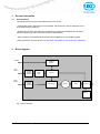
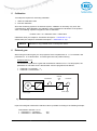
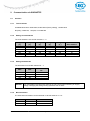
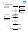
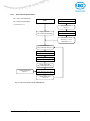
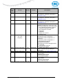
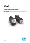
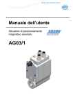
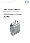
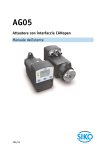
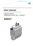
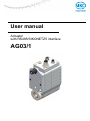
User manual Actuator with RS485/SIKONETZ5 interface AG03/1 1 1.1 2 3 3.1 3.2 3.3 3.4 4 4.1 5 6 7 7.1 7.2 7.3 8 9 9.1 9.2 9.3 9.4 9.5 9.6 9.7 9.8 General Information.......................................................................................................................... 4 DOCUMENTATION ........................................................................................................................ 4 Block diagram ................................................................................................................................... 4 Display and operating elements ....................................................................................................... 5 GENERAL INFORMATION............................................................................................................... 5 OPERATING KEYS ........................................................................................................................ 5 DIP SWITCH ................................................................................................................................ 5 LED DISPLAYS ............................................................................................................................ 6 Functional description ...................................................................................................................... 6 CONTROL OF THE DRIVE............................................................................................................... 6 4.1.1 Operating modes ................................................................................................................. 6 4.1.1.1 Positioning mode ......................................................................................................... 6 4.1.1.1.1 Loop positioning ...................................................................................................... 7 4.1.1.2 Inching mode ............................................................................................................... 8 4.1.1.2.1 Inching mode 1 ....................................................................................................... 8 4.1.1.2.2 Inching mode 2 ....................................................................................................... 8 4.1.1.3 Rotational speed mode ................................................................................................ 9 4.1.2 Torque deactivation ............................................................................................................. 9 4.1.3 Reset factory settings via DIP switches............................................................................. 10 Calibration ...................................................................................................................................... 11 External gear .................................................................................................................................. 11 Warnings / Errors ........................................................................................................................... 12 W ARNINGS ................................................................................................................................ 12 ERRORS ................................................................................................................................... 12 7.2.1 Error codes ........................................................................................................................ 12 ACKNOWLEDGMENT OF ERRORS ................................................................................................. 12 Parameter description .................................................................................................................... 13 Communication via SIKONETZ5.................................................................................................... 19 INTERFACE ................................................................................................................................ 19 9.1.1 Technical Data ................................................................................................................... 19 9.1.2 Setting of node address ..................................................................................................... 19 9.1.3 Setting the baud rate ......................................................................................................... 19 9.1.4 Bus termination .................................................................................................................. 19 DATA EXCHANGE ....................................................................................................................... 20 TELEGRAM SETUP ..................................................................................................................... 20 9.3.1 Command .......................................................................................................................... 20 9.3.2 Node ID .............................................................................................................................. 20 9.3.3 Parameter address ............................................................................................................ 20 9.3.4 Control word ...................................................................................................................... 21 9.3.5 Status word: ....................................................................................................................... 21 9.3.6 Data ................................................................................................................................... 21 9.3.7 Check sum ......................................................................................................................... 21 SYNCHRONIZATION .................................................................................................................... 21 ERROR TELEGRAM..................................................................................................................... 21 9.5.1 SIKONETZ5 error codes ................................................................................................... 22 ERRORS ................................................................................................................................... 22 COMMUNICATION MONITORING ................................................................................................... 22 9.7.1 Bus timeout ........................................................................................................................ 22 9.7.2 Locking the programming mode ........................................................................................ 23 FUNCTIONAL DESCRIPTION OF THE CONTROL UNITS ..................................................................... 23 9.8.1 System Status Word .......................................................................................................... 23 9.8.2 Control word in positioning mode (master slave) .......................................................... 25 9.8.3 Status word: Positioning mode (slave master) ............................................................. 26 9.8.4 Flow chart of positioning mode .......................................................................................... 27 9.8.5 Control word in speed mode .............................................................................................. 28 9.8.6 Status word in speed mode ............................................................................................... 29 9.8.7 Flow chart of speed mode ................................................................................................. 30 AG03/1-RS485/SIKONETZ5 x Date: 31.03.2014 Page 2 of 36 Art.no. 86679 Mod. status 112/14 9.9 PARAMETERIZATION VIA SIKONETZ5 ........................................................................................ 31 9.9.1 Example: Read parameter ................................................................................................. 36 9.9.2 Example: Write parameter ................................................................................................. 36 AG03/1-RS485/SIKONETZ5 x Date: 31.03.2014 Page 3 of 36 Art.no. 86679 Mod. status 112/14 1 General Information 1.1 Documentation The following documents are associated with this document: • Product data sheet, describes the technical data, the dimensions, the pin assignment, the accessories and the order key. • Installation instruction, describes the mechanical and electrical installation with all safetyrelevant conditions and the associated technical specifications. • User manual for commissioning the actuator and integrating it into a fieldbus system. These documents can also be found at http://www.siko-global.com/en-de/service-downloads. 2 Block diagram RS485 Galvanic isolation +UB control +UB Output Reverse polarity protection Power pack Reverse polarity protection Control Output stage Motor Gear Encoder Battery Fig. 1: Block diagram AG03/1-RS485/SIKONETZ5 x Date: 31.03.2014 Page 4 of 36 Art.no. 86679 Mod. status 112/14 3 3.1 Display and operating elements General Information The actuator has two operator keys (1, 2), two LEDs (3, 4) and one 10-pin DIP switch (5). 5 3 4 1 2 Fig. 2: Display and operating elements 3.2 Operating keys Manual setup mode (corresponding to inching mode 2) can be started by means of the operator keys. This makes it possible to move the actuator without a superordinate control. Key (1) clockwise movement Key (2) counter-clockwise movement 3.3 DIP switch Bus-specific settings can be made via the DIP switch For a more detailed description of the functions refer to the bus-specific part of this manual. The factory settings can also be restored by means of the DIP switch (see chapter 4.1.3: Restore factory settings via DIP switches). AG03/1-RS485/SIKONETZ5 x Date: 31.03.2014 Page 5 of 36 Art.no. 86679 Mod. status 112/14 3.4 LED displays LED State on blink 1 x blink 2 x blink 3 x blink 4 x blink 5 x LED3 green blink 6 x blink 7 x blink 8 x blink 9 x blink 10 x off on LED4 orange off Table 1: LED displays 4 Color Description Supply voltage of the output stage is applied Error: Undervoltage: Error: Shaft blocked Error: Overcurrent Error: Output stage excess temperature Error: SIN COS monitoring Error: Internal error Error: Overvoltage Error: Checksum error SIKONETZ5 Error: Timeout SIKONETZ5 Error: Low battery voltage: Supply voltage of the output stage not applied Bus operation active no bus operation Functional description 4.1 Control of the drive The drive can be moved manually via the 1,2 keys without upstream control. The drive can be controlled and configured in the bus operating mode. 4.1.1 Operating modes The following operating modes are distinguished: positioning mode and speed mode. In the positioning mode there is the additional option of traveling in inching operation. 4.1.1.1 Positioning mode In the positioning mode, positioning to the specified set point is executed by means of a ramp function (see Fig. 3) calculated on the basis of the actual position as well as the programmed controller parameters P (proportional factor), I (integral factor), D (differential factor), acceleration and speed. Upon activation of the travel order, the actuator accelerates to the specified speed with the acceleration programmed. The measure of delay to the required value is defined by the parameter ‘a-pos’ as well. Alternately, a value deviating from acceleration can be chosen for delay (see parameter 'd-Pos'). If the actual position is within the programmed window, this condition will be signaled in the system status word and in the SIKONETZ5 status word. You can define the behavior of the actuator upon reaching the programmed window. Changing controller parameters during a positioning process does not influence the current positioning operation. AG03/1-RS485/SIKONETZ5 x Date: 31.03.2014 Page 6 of 36 Art.no. 86679 Mod. status 112/14 Velocity Velocity (parameter no. 5) Delay (parameter no. 4) Acceleration (parameter no. 4) Delay (parameter no. 74) Start position Time target position Fig. 3: Ramp travel, direct positioning mode 4.1.1.1.1 Loop positioning If the actuator is operated on a spindle or an additional gear, the spindle or external gear backlash can be compensated by means of loop positioning. In this case, traveling to the target value is always from the same direction. This direction of approach can be defined (see chapter 8: Parameter description Parameter no. 19). Example: The direction from which every target position shall be driven to is positive. Case 1 new position is greater than actual position: direct travel to the target position Case 2 new position is smaller than actual position: The actuator drives beyond the target position by the loop length; afterwards, the set point is approached in positive direction. Positioning: loop + Loop length Positioning in positive direction - Positioning in negative direction + Set point Fig. 4: Loop+ positioning AG03/1-RS485/SIKONETZ5 x Date: 31.03.2014 Page 7 of 36 Art.no. 86679 Mod. status 112/14 4.1.1.2 Inching mode Inching mode is enabled in the ‘positioning mode’ only. You can program via parameters acceleration as well as speed in the inching mode. NOTICE 4.1.1.2.1 There is no compensation for spindle backlash (loop positioning) in this operating mode! Inching mode 1 The drive travels once from the current actual position by the position ‘Delta Tipp’ depending on the mathematical sign of the value entered. ‘Delta Tipp‘ < 0: ‘Delta Tipp‘ > 0: negative travel direction positive travel direction If the ‘Spindle pitch’ parameter is programmed to zero, then the traveling way occurs by increments. If ‘Spindle pitch’ is unequal zero, then the information of the ‘Delta Tipp’ parameter refers to the travel distance in 1/100 mm. NOTICE Reaching of the target position will be signaled accordingly. The following conditions must be met for enabling the start of inching modes 1 and 2: The actuator must not be switched to error No active travel job Supply voltage of the output stage is applied NOTICE 4.1.1.2.2 If the actual position is outside the programmed limiting values, then traveling from this position in the respective direction is possible by means of inching mode 1 or 2! Inching mode 2 The actuator travels from the current actual position as long as the relevant command is active. You can influence the inching speed via two parameters and it will be calculated in the actuator as illustrated in the example below: v - Tipp (Parameter no. 9) = 10 rpm (can only be changed in the idle state) Offset inching 2 (Parameter no. 30) = 85 % (can be changed during inching operation) The resulting inching speed in this example will be: Inching speed = v - Tipp * Offset inching 2 = 10 rpm * 85 % = 9 rpm The results are always rounded to integers. The minimum speed is 1 rpm. AG03/1-RS485/SIKONETZ5 x Date: 31.03.2014 Page 8 of 36 Art.no. 86679 Mod. status 112/14 4.1.1.3 Rotational speed mode With the set point enabled, the actuator when in the rotational speed mode accelerates to the target speed and maintains this speed until the set point is disabled or a different target speed specified. The speed is adjusted immediately to the new value when the rotational target speed is changed. The arithmetical sign of the set point determines the travel direction in the rotational speed mode. Velocity Target speed (set point) Disable operation Disable target value or set point = 0 Acceleration Parameter no. 8 'Stop' Set point enabled Time Fig. 5: Ramp speed mode The following conditions must be met for enabling the start of the rotational speed mode: The actuator must not be switched to error No active travel job Supply voltage of the output stage is applied NOTICE 4.1.2 Limits 1 + 2 are inactivated in this operational mode. Torque deactivation Via the torque deactivation parameter (see chapter 8: Parameter description Parameter no. 75) a switch-off threshold is defined. The values are indicated in % of nominal current. With a parameter value of 125 %, torque disable is deactivated. The drive decelerates with max. delay when the switch-off threshold is exceeded. The drive continues to be controlled. NOTICE Active torque deactivation causes no error! AG03/1-RS485/SIKONETZ5 x Date: 31.03.2014 Page 9 of 36 Art.no. 86679 Mod. status 112/14 Active torque disable is reported via SW.12 = 1. This bit will be automatically reset when the current travel order is continued. 4.1.3 NOTICE This function is available in the positioning mode only! NOTICE The actual motor current cannot be indicated by measuring the supply current. With cycled output stages, the supply current does not correspond to the motor current. Actual motor current can be read via the interface. Reset factory settings via DIP switches Procedure for restoring the factory settings via the 10-pin DIP switch: 1. Switch off supply voltage 2. Set DIP switches 1 – 8 depending on the parameters to be reset: Reset all parameters to factory settings (see chapter 8: Parameter description) Reset only standard parameters to factory settings (see chapter 8: Parameter description) Reset only controller parameters to factory settings (see chapter 8: Parameter description) Reset only bus parameters to factory settings (see chapter 8: Parameter description) 3. Turn on supply voltage. AG03/1 acknowledges with alternating blinking of the status LED and the bus LED. 4. Switch off supply voltage. 5. Setting of the original bus address and baud rate via DIP switches 1 - 7. 6. DIP switch number 8 must be set to the OFF position. 7. The parameters chosen before will have the factory settings again after switching on supply voltage. AG03/1-RS485/SIKONETZ5 x Date: 31.03.2014 Page 10 of 36 Art.no. 86679 Mod. status 112/14 5 Calibration Two steps are required for executing calibration: 1. Write the calibration value 2. Execute calibration Since the measuring system is an absolute system, calibration is necessary only once with commissioning. With calibration, the calibration value is adopted for calculation of the position value. The following equation is applied in case of calibration: Position value = 0 + calibration value + offset value Calibration value (see chapter 8: Parameter description Parameter no. 14) Offset value (see chapter 8: Parameter description Parameter no. 32) NOTICE 6 Calibration is only possible when no travel job is active! External gear When using an external gear you can program a factor via parameter no. 11 ‘ü-numerator’ and parameter no. 12 ‘ü-denominator’ to include gear ratio into position sensing. Example (see Fig. 6): The actuator is operated on a gear with transmission reduction of 5:1. For this purpose, the parameters ‘ü-numerator’ and ‘ü-denominator’ must be programmed as follows: Parameter ‘ü-numerator‘ : 5 Parameter ‘ü-denominator‘: 1 5 revolutions external gear 5:1 1 revolution M Gear output Internal gear Fig. 6: External gear Input of an odd gear transmission reduction value is possible according to the following example: Transmission reduction = 3.78 Parameter ‘ü – numerator:’ Parameter ‘ü – denominator’: AG03/1-RS485/SIKONETZ5 x Date: 31.03.2014 378 100 Page 11 of 36 Art.no. 86679 Mod. status 112/14 7 Warnings / Errors 7.1 Warnings Warnings do not influence the operation of the positioning drive. Warnings disappear after correcting the cause. Possible warnings: 7.2 Battery voltage for absolute encoder is below limit exchange battery within the next 6 months. Errors Errors cause an immediate stop of the positioning drive. An error is signaled in the SW.7 = 1 status word and with a blink code on LED3. The error messages are entered in the error memory in the order of their detection. The last 10 error messages are displayed when the error memory is full. The cause of error can be tracked down with the help of the error codes. 7.2.1 Error codes Error code Error 0x00 No error 0x06 Low battery voltage: 0x07 Low control electronics voltage 0x08 Excess control electronics voltage 0x09 Excess power electronics voltage 0x0A Output stage excess temperature 0x0C Shaft blocked 0x0D Power electronics: supply missing 0x20 Internal error 0x21 Overcurrent 0x80 Checksum SIKONETZ5 0x81 Timeout SIKONETZ5 Table 2: Error codes 7.3 Acknowledgment of errors Errors cannot be acknowledged until the cause of the eror has been corrected. Acknowldgement is via the bus. AG03/1-RS485/SIKONETZ5 x Date: 31.03.2014 Page 12 of 36 Art.no. 86679 Mod. status 112/14 8 Parameter description Column S C Explanation "S" = Parameter transferred is saved in the device non-volatilely "-" = Parameter transferred is saved in the device volatilely Parameter class 1 = Standard parameter 2 = Controller parameter 3 = reserved 4 = Bus parameter 5 = General parameter No. Name 1 4 Controller parameter P Controller parameter I Controller parameter D a - Pos 5 2 Selection / value 1 - 500 Default Description S C 100 P gain of controller applies to all operating modes (positioning mode, speed mode, inching mode) I gain of controller applies to all operating modes (positioning mode, speed mode, inching mode) D gain of controller applies to all operating modes (positioning mode, speed mode, inching mode) Acceleration in the positioning mode: values in % 100 % correspond to 4 rps² Maximum velocity in the positioning mode: values in rpm gear 48:1 max. 100 rpm gear 24:1 max. 200 rpm Acceleration in rotational speed mode values in % 100 % correspond to 4 rps² reserviert Acceleration in inching mode 1/2: values in % 100 % correspond to 4 rps² Maximum speed in inching mode 1/2 values in rpm gear 48:1 max. 100 rpm gear 24:1 max. 200 rpm Operating mode: Positioning mode Positioning window If the actual position of the drive is within the programmed set point ± this window, this is signaled by setting bit 3 in the drive's status word. Spindle pitch = 0: Values refer to increments Spindle pitch > 0: Values refer to travel distance in 1/100 mm Operating mode: Speed mode: If the actual rotational speed is within the target rotational speed ± this window, this is signaled by setting bit 3 in the drive's system status word. S 2 S 2 S 2 S 2 S 2 S 2 S 2 S 2 S 1 0 - 500 5 0 - 500 0 1 - 100 50 v - Pos 1 - 100 1 - 200 30 6 a - rot 1 - 100 50 7 8 a - inch 1 - 100 50 9 v - inch 1 - 100 1 - 200 30 10 Pos window 0 - 1000 10 3 AG03/1-RS485/SIKONETZ5 x Date: 31.03.2014 Page 13 of 36 Art.no. 86679 Mod. status 112/14 Selection / value 1 - 10000 No. Name 11 ü - numerator 12 üdenominator 1 - 10000 1 13 Spindle pitch 0 - 1000000 0 14 Calibration value -999999 to 999999 0 15 Limit 1 -9999999 to 9999999 1000000 16 Limit 2 -9999999 to 9999999 1000000 AG03/1-RS485/SIKONETZ5 Default Description S C 1 Numerator gear ratio: a transmission factor can be programmed here when a gear is used. Denominator gear ratio a transmission factor can be programmed here when a gear is used. Spindle pitch Spindle pitch parameter = 0: Position value is output in increments (1600 increments per revolution of the driving shaft). Spindle pitch parameter > 0: (when operating the actuator on a spindle) The position value is output as traveling distance in 1/100 mm, rather than in increments. Input of required position is now in 1/100 mm as well. E. g., spindle with a pitch of 2 mm. Spindle pitch parameter = 200. Calibration value Changes to the calibration value are adopted for calculation of the position value via command only after calibration Position value = 0 + calibration value + offset value Operating mode: Positioning mode: Limit 1 Spindle pitch = 0: Values refer to increments Spindle pitch > > 0: values refer to travel distance in 1/100 mm If drive’s position is beyond the range defined by limit 1 and limit 2 (travel range), traveling will only be possible in inching mode in the direction of the travel range. Caution! Limit monitoring is deactivated if ‘limit 1’ is equal ‘limit 2’. Take into account that there will be a jump of the actual position when the resolution of the absolute value encoder is exceeded! Operating mode: Speed mode: irrelevant Operating mode: Positioning mode: Limit 2 Spindle pitch = 0: Values refer to increments Spindle pitch > > 0: values refer to travel distance in 1/100 mm If the drive's position is outside the area defined by limit 1 and limit 2 (traveling range) then traveling is only enabled in inching mode in the direction of the traveling range. Caution! Limit monitoring is deactivated if ‘limit 1’ is equal ‘limit 2’. Take into account that there will be a jump of the actual position when the resolution of the absolute value encoder is exceeded! Operating mode: Speed mode: irrelevant S 1 S 1 S 1 S 1 S 1 S 1 x Date: 31.03.2014 Page 14 of 36 Art.no. 86679 Mod. status 112/14 Selection / value -1000000 to 1000000 No. Name 17 Delta inch 18 Sense of rotation i,e i 19 Pos type direct loop + loop - direct 20 Operating mode positioning mode / speed mode Positioning mode Node address read-only - Set point see Column Description 0 21 22 23 24 AG03/1-RS485/SIKONETZ5 Default Description S C 1600 Delta traveling distance with inching operation 1: indicates the relative traveling distance. positive value positive travelling direction negative value negative travelling direction Spindle pitch = 0: Values refer to increments Spindle pitch > 0: values refer to travel distance in 1/100 mm Counting direction of the measuring system: With shaft rotating counter-clockwise (view on the clamping ring of the actuator) i sense of rotation (cw): positive counting direction e sense of rotation (ccw): negative counting direction Operating mode: Positioning mode: Type of positioning direct: direct traveling from actual position to target value loop +: traveling to the target value occurs always in positive direction to compensate for spindle play loop -: traveling to the target value occurs always in negative direction to compensate for spindle play Caution! Loop positioning only in positioning mode Operating mode: Speed mode: irrelevant Operating mode: Positioning mode (see chapter 4.1.1.1: Positioning mode) Operating mode: Speed mode: (see chapter 4.1.1.3: Speed mode) S 1 S 1 S 1 S 1 - - - 1 x Date: 31.03.2014 reserved Setting of the node address is via the DIP switch reserved Operating mode: Positioning mode indicates absolute target position. Spindle pitch = 0: Values refer to increments Spindle pitch > > 0: values refer to travel distance in 1/100 mm Value range: depends on the preprogrammed limits (parameters 15/16) Operating mode: Speed mode: indicates the target rotational speed in rpm. Value range: Transmission 48:1 max. 100 rpm Transmission 24:1 max. 200 rpm Page 15 of 36 Art.no. 86679 Mod. status 112/14 Selection / value 0-1 No. Name 25 Stop mode Inching 2 26 Inpos mode 0-2 0 27 Loop length 0 - 30000 800 28 Contouring error limit 1 - 30000 400 30 Inching 2 Offset 10 – 100 100 31 Type of acceleration Inching mode 2 0–1 0 32 Offset -999999 to 999999 0 AG03/1-RS485/SIKONETZ5 Default Description S C 0 Stop mode inching mode 2 / Inching key operation: The stop behavior of inching mode 2 or inching key operation can be configured in different ways. Stop mode = 0 stop with maximum delay Stop mode = 1 stop with programmed delay (parameter no. 8) Operating mode: Positioning mode With this parameter you can define the behavior of the actuator upon reaching the position window: Inposmode = 0 Position control to set point Inposmode = 1 Position control OFF and short circuit of the motor windings Inposmode = 2 Position control OFF and enabling of the drive Operating mode: Speed mode: irrelevant Operating mode: Positioning mode Values refer to increments Operating mode: Speed mode: irrelevant Contouring error limit: exceeding the contouring error limit during ongoing positioning results in a “Contouring error” error. Inching operation 2 The inching speed in Inching operation 2 can be influenced via this parameter Values are entered in percentage of parameter no. 9 Inching operation 2 The type of acceleration can be set with this parameter. 0 = static acceleration Acceleration to final speed occurs in one step as defined under parameter no. 8. 1 = incremental acceleration Acceleration occurs to final speed as defined under parameter no. 8 with the following steps: 4 s to 20 % of final speed 2 s to 50 % of final speed 1 s to 100 % of final speed Offset value: Changes to the offset value are immediately considered in the calculation of the position value. The following equation applies to calibration: Position value = 0 + calibration value + offset value S 1 S 1 S 1 S 1 - 1 S 1 S 1 x Date: 31.03.2014 Page 16 of 36 Art.no. 86679 Mod. status 112/14 Selection / value read-only No. Name 33 Baud rate RS485 35 Bus Timeout 0 – 20 20 36 Reply parameter Write to set point 0–8 1 46 Programming mode: Configuration Programming mode 0–1 0 0–1 0 Output stage temperature Voltage of controller Voltage of output stage Voltage of battery Motor current Read only Read only Read only - Read only Read only Read only - Read only - Read only Read only 47 50 51 52 53 54 55 Actual position 56 Actual rotational speed Serial number Production date 57 58 AG03/1-RS485/SIKONETZ5 Default Description S C - The baud rate is set via DIP switches SW.6 + SW.7 0 = 19200 baud 1 = 57600 baud 2 = 115200 baud SIKONETZ5 Caution! Unintended device reactions. Unintended device reactions may occur with missing time monitoring (0= deactivated) and concurrent cable break. Time monitoring is activated ex-factory. Mode: Time monitoring "deactivated = 0" is only allowed for test purposes. Activate time monitoring after test mode. 1-20 = Indication of bus timeout values in x100 ms SIKONETZ5 This parameter defines the reply to the Write set point command 0 = set point 1 = Actual value 2 = Output stage temperature 3 = Controller voltage 4 = Output stage voltage 5 = Battery voltage 6 = Motor current: 7 = Actual position 8 = Actual rotational speed SIKONETZ5 0 = no programming mode 1 = apply programming mode SIKONETZ5 0 = Programming mode Off 1 = Programming mode On Output stage temperature: Values in 1/10 °C Controller voltage Values in 1/10 V Output stage voltage: Values in 1/10 V - - S 4 S 4 S 5 - 1 - - - - - - Battery voltage: Values in 1/100 V Motor current: Values in mA Actual position: Spindle pitch = 0: values in increments Spindle pitch > 0: values in 1/100 mm Actual rotational speed: values in rpm - - - - - - - - - Serial number S - - Production date: Format: DDMMYYYY S - - - x Date: 31.03.2014 Page 17 of 36 Art.no. 86679 Mod. status 112/14 No. Name 59 62 Software version Main controller Software version Secondary controller 1 number of Errors Error 1 63 Error 2 64 Error 3 65 Error 4 66 Error 5 67 Error 6 68 Error 7 69 Error 8 70 Error 9 71 Error 10 72 Step-down gear System Status Word d – Pos 60 61 73 74 75 Torque disable Selection / value Read only Default Description S C - Main controller software version S - Read only - Secondary controller 1 software version S - Read only Read only Read only Read only Read only Read only Read only Read only Read only Read only Read only Read only Read only 1 – 101 - Number of errors in the error memory S - - Error 1 S - - Error 2 S - - Error 3 S - - Error 4 S - - Error 5 S - - Error 6 S - - Error 7 S - - Error 8 S - - Error 9 S - - Error 10 S - - Step-down gear S - - System Status Word - - 101 S 2 20 - 125 125 Delay in the positioning mode: 101= Delay determined by parameter no. 4 1-100 = Delay in per cent 100 % correspond to 4 rps² Operating mode: Positioning mode This parameter determines the threshold of torque disable The values are indicated in % of nominal current. Value 125: Torque disable deactivated Operating mode: Speed mode: irrelevant S 1 Table 3: Parameter description AG03/1-RS485/SIKONETZ5 x Date: 31.03.2014 Page 18 of 36 Art.no. 86679 Mod. status 112/14 9 Communication via SIKONETZ5 9.1 9.1.1 Interface Technical Data Available baud rates: 19200 baud, 57600 baud (factory setting), 115200 baud No parity, 8 data bits, 1 stop bit, no handshake 9.1.2 Setting of node address The node address is set via DIP switches 1 – 5. SW1 SW2 SW3 0 1 2 [2 ] [2 ] [2 ] OFF OFF OFF ON OFF OFF OFF ON OFF : : : OFF ON ON ON ON ON Table 4: Setting of node address 9.1.3 SW4 3 [2 ] OFF OFF OFF : ON ON SW5 4 [2 ] OFF OFF OFF : ON ON Set Slave address 0 1 2 : 30 31 Setting the baud rate The baud rate is set via DIP switches 6 – 7. SW6 SW7 OFF OFF ON OFF OFF ON ON ON Table 5: Setting the baud rate NOTICE 9.1.4 Baud rate set 57600 baud 115200 baud 19200 baud - The node address and baud rate settings are only read in when switching on supply voltage. Changing the settings during operation has no effect. Bus termination The internal bus terminator can be switched in via DIP switches 9 + 10: SW9 SW10 Bus termination OFF OFF ON ON Table 6: Bus termination AG03/1-RS485/SIKONETZ5 x Date: 31.03.2014 deactivated active Page 19 of 36 Art.no. 86679 Mod. status 112/14 NOTICE 9.2 Please note that both DIP switches are always required to ensure the correct function of bus termination. Data exchange The protocol functions according to the master – slave principle. The actuator acts as a slave. Every act of communication must be initiated by the master. When the master has sent a command telegram, the addressed slave sends a reply telegram. Broadcast commands are an exception, they remain always unanswered by the slave. The protocol is optimized for cyclical data exchange. The relevant data such as set point and actual value can be transferred between master and slave by a single telegram exchange. The parameter to be returned by the slave as a reply to the master’s Write set point command can be defined via the “Write Set point reply parameter”. 9.3 Telegram setup CW, SW and data are transferred in the Big-Endian format. Command telegram (from master) 1. Byte Command 2. Byte Node ID 3. Byte Parameter address 4. Byte 5. Byte 6. Byte 7. Byte CW 8. Byte 9. Byte 10.Byte check sum 9. Byte 10.Byte check sum data Reply telegram (by slave) 1. Byte Reply 9.3.1 2. Byte Node ID 3. Byte Parameter address 4. Byte 5. Byte 6. Byte 7. Byte SW 8. Byte data Command 0x00 = read 0x01 = write 0x02 = broadcast 9.3.2 Node ID Node address (see chapter 8: Parameter description Parameter no. 22). 9.3.3 Parameter address Description, see chapter 9.9: Parameterization via SIKONETZ5. AG03/1-RS485/SIKONETZ5 x Date: 31.03.2014 Page 20 of 36 Art.no. 86679 Mod. status 112/14 9.3.4 Control word Control word (CW) master to slave. 9.3.5 Status word: Status word (SW) slave to master. 9.3.6 Data Range for data exchange. Size: 4 bytes. 9.3.7 Check sum For checking error-free data transfer, a check sum is formed at the end of the telegram. The check sum is the exclusive-OR-link of bytes 1 – 9. Check sum [Byte10] = [Byte1] XOR [Byte2] XOR [Byte3] XOR [Byte4] XOR [Byte5] XOR [Byte6] XOR [Byte7] XOR [Byte8] XOR [Byte9] The following applies for checking the telegram received: [Byte1] XOR [Byte2] XOR [Byte3] XOR [Byte4] XOR [Byte5] XOR [Byte6] XOR [Byte7] XOR [Byte8] XOR [Byte9] XOR [Byte 10] = 0 With a result unequal 0 a transmission error is to be assumed. 9.4 Synchronization Byte/telegram synchronization is via "Timeout" The intervals of the individual bytes of a telegram must not exceed the value of 10 ms. If an addressed device does not respond, the master may send a new telegram not earlier than after 30 ms. 9.5 Error telegram Illegal entries are replied with an error telegram. An error telegram consists of parameter address 0xFD and an error code. The error code is in the data range of the reply telegram. The error code is divided in two bytes. Code 1 describes the error proper, code 2 contains additional information if available. In the following example it was attempted to write a value of 1000 to the v-Pos parameter address. However, a maximum value of only 30 is admissible for this parameter. Telegram from master to slave 1. Byte Command 0x01 2. Byte 3. Byte Node ID 0x01 Parameter address 0x14 AG03/1-RS485/SIKONETZ5 4. Byte 5. Byte 6. Byte 7. Byte CW 0x00 x Date: 31.03.2014 8. Byte 9. Byte 10.Byte 0xE8 check sum 0xFF data 0x00 Page 21 of 36 0x00 0x00 Art.no. 86679 0x03 Mod. status 112/14 Reply telegram from slave 1. Byte Command 0x01 9.5.1 2. Byte 3. Byte Node ID 0x01 Parameter address 0xFD 4. Byte 5. Byte 6. Byte SW 0x00 0x21 0x00 7. Byte 8. Byte 9. Byte 10.Byte data Code 2 0x00 0x02 Code 1 0x82 check sum 0x5C SIKONETZ5 error codes Code 1 Description Code 2 0x80 0x81 Checksumme SIKONETZ5 Timeout SIKONETZ5 0x82 Value rage exceeded / inadequate 0x83 Unknown parameter 0x84 Access is not supported 0x85 Error due to device status 0x00 0x00 0x00 0x01 0x02 0x00 0x00 0x01 0x02 0x00 0x01 0x02 0x03 Description No further information available No further information available No further information available Value < MIN Value > MAX No further information available No further information available Write on read only Read on write only No further information available EEPROM write access active Positioning active. Programming locked Table 7: SIKONETZ5 Error codes 9.6 Errors If a slave is in the error state, the slave signals the error with ZSW.7 = 1. An error must be acknowledged with CW.5 = 0/1. If the cause of the error has not been resolved at the time of acknowledgment, the error will not be reset. After acknowledgment of an error, the slave is in the switch-lock state. The switch-lock can be released via a negative flank on CW.0 or CW.1 or CW.2. Errors are stored in the error memory and can be read out. In order to receive the last error occurring the number of errors must first be read in parameter address 0x80. With 0x80 + number of errors the parameter address with the latest error is received. Under this address the error code can be found (see chapter 7.2.1: Error codes). 9.7 9.7.1 Communication monitoring Bus timeout The first telegram received by the slave starts time monitoring. Every new telegram recognized as valid by the slave (correct check sum) triggers time monitoring. If timeout occurs during an active travel job, this will result in the Timeout error, i. e. the current travel job is canceled. Thus, a broken cable can be detected for instance and the actuator set into a defined state. For this purpose the master must address all slaves cyclically. AG03/1-RS485/SIKONETZ5 x Date: 31.03.2014 Page 22 of 36 Art.no. 86679 Mod. status 112/14 9.7.2 Locking the programming mode Locking of programming is controlled via parameter "Programming mode: Configuration" (see chapter 8: Parameter description Parameter no. 46). If it is activated, locking must be disabled by a write command on parameter "Programming mode" (see chapter 8: Parameter description Parameter no. 47) prior to write access to a parameter which is stored nonvolately in the device. Correspondingly, locking should be re-enabled immediately after write access. This approach enhances protection from unwanted configuration. Write access to locked parameters is answered with "Error due to device status" (see chapter 9.5.1: SIKONETZ5 error codes). 9.8 9.8.1 Functional description of the control units System Status Word The system status word consists of 2 bytes and reflects the state of the drive independent of the operating mode. The system status word can be read as a parameter. The mode-dependent status words are available for cyclical data exchange. High Byte 15 0 14 0 13 1 12 0 11 1 Low Byte 10 0 Bit number 9 8 7 6 0 1 0 1 2 9 Fig. 7: System Status Word 5 0 4 4 0 3 1 2 0 1 0 0 0 8 Example (gray background): binary: 0010 1001 0100 1000 hex: 2 9 4 8 The table below informs about the meaning of the individual bits of the status word. System Status Word: Bit Bit 0 Bit 1 Bit 2 Bit 3 State ‘0‘ ‘0‘ ‘0‘ ‘1‘ ‘0‘ ‘1‘ ‘0‘ Bit 4 ‘1‘ ‘0‘ AG03/1-RS485/SIKONETZ5 Description irrelevant irrelevant irrelevant Operating mode: Positioning mode In Position Actual position is within the positioning window of the programmed target value. Actual position is outside the positioning window of the programmed target value. Operating mode: Speed mode: In Position Actual speed is inside the specified tolerance window of target speed Actual speed is outside the specified tolerance window. Drive travels: Drive travels Drive stands still (rotational speed <2 rpm) x Date: 31.03.2014 Page 23 of 36 Art.no. 86679 Mod. status 112/14 Bit Bit 5 State Description Operating mode: Positioning mode: upper limit ‘1‘ The actual position is above the programmed upper limit of limit 1+2. Traveling is possible only in negative direction in inching mode. ‘0‘ Actual position is below the programmed limiting value. Operating mode: Speed mode: irrelevant ‘0‘ Operating mode: Positioning mode: lower limit Bit 6 ‘1‘ The actual position is below the programmed lower limit of limit 1+2. Traveling is possible only in negative direction in inching mode. ‘0‘ Actual position is above the programmed limiting value. Operating mode: Speed mode: irrelevant ‘0‘ Driver state: Bit 7 ‘1‘ Motor is enabled ‘0‘ Motor in control Error: Bit 8 ‘1‘ Drive has switched to error. The cause of the error must be cleared and acknowledged via ‘CW.7=1’. Cause of error, see chapter 7. ‘0‘ No error present Operating mode: Positioning mode Loop travel Bit 9 ‘1‘ If travel direction unequal start direction ( with loop travel ) ‘0‘ If travel direction equal start direction Operating mode: Speed mode: irrelevant ‘0‘ Output stage supply voltage Bit 10 ‘1‘ Supply voltage of the output stage not applied No traveling of the drive is possible! ‘0‘ Supply voltage of the output stage is applied Ready for travel: Bit 11 ‘1‘ Not ready for travel ‘0‘ Ready for travel: Drive not in error condition No active positioning Supply voltage of the output stage is applied Actual position within limits (only positioning mode) Battery voltage: Bit 12 ‘1‘ battery voltage too low for absolute encoder. Replace the battery within half a year after notice of error bit! ‘0‘ Battery voltage OK Motor current: Bit 13 ‘1‘ Motor current beyond permissible range. If this condition persists longer than 4 s, the drive will switch to Error. ‘0‘ Motor current within permissible range. Operating mode: Positioning mode Status Bit 14 ‘1‘ Positioning active in positioning mode. ‘0‘ Positioning inactive Operating mode: Speed mode: irrelevant ‘0‘ Contouring error: Bit 15 ‘1‘ Contouring error the actuator cannot reach the preset speed due to too high load. This state should be avoided! Remedy: reduce programmed speed! ‘0‘ No contouring error actual speed corresponds with required speed. Table 8: System Status Word AG03/1-RS485/SIKONETZ5 x Date: 31.03.2014 Page 24 of 36 Art.no. 86679 Mod. status 112/14 9.8.2 Control word in positioning mode (master slave) Bit Bit 0 OFF1 (enable) Bit 1 OFF 2 (max. delay) Bit 2 OFF 3 (progr. delay) Bit 3 Intermediate stop Bit 4 Start travel job Bit 5 Acknowledge error Bit 6 Inching mode 1 Description 0 = OFF1 active Current travel job is canceled. The actuator is activated. 1 = OFF1 inactive 0 = OFF2 active Current travel job is canceled. The actuator is decelerated with max. delay, the actuator continues to be controlled. 1 = OFF2 inactive 0 = OFF3 active Current travel job is canceled. The actuator is decelerated with prog. delay, the actuator continues to be controlled. 1 = OFF3 inactive 0 = no intermediate stop 1 = intermediate stop active Positive flank starts a travel job Positive flank acknowledges an error Afterwards, the actuator changes to the switch-lock state. 0 = no inching mode1 If the travel job is not completed yet it will be canceled. 1 = inching operation 1 As long as this bit is set, the actuator travels the distance specified in parameter Delta Inch. Bit 7 0 = no inching mode 2 positive Inching mode 2 positive 1 = inching mode 2 positive The actuator travels in positive direction Bit 8 0 = no inching mode 2 negative Inching mode 2 negative 1 = inching mode 2 negative The actuator travels in negative direction Bit 9 -15 Reserved, always 0 Table 9: Control word in positioning mode SIKONETZ5 AG03/1-RS485/SIKONETZ5 x Date: 31.03.2014 Page 25 of 36 Art.no. 86679 Mod. status 112/14 9.8.3 Status word: Positioning mode (slave master) Bit Bit 0 Supply Bit 1 Readiness to travel Bit 2 upper limit Bit 3 lower limit: Bit 4 Actuator travels/stands still Bit 5 Inpos Bit 6 Active travel job Bit 7 Error Description 0 = Output stage voltage missing 1 = Supply voltage of the output stage is applied 0 = not ready to travel 1 = ready to travel 0 = no violation of limit 1 = uppper limit exceeded 0 = no violation of limit 1 = lower limit undercut 0 = actuator stands still 1 = actuator travels: 0= Actuator is outside the position window. 1 = Actuator is inside the position window. 0 = no active travel job 1 = active travel job 0 = no error 1 = Error Acknowledgment with positive flank on Control word bit 5 Bit 8 0 = operation not enabled Operation enabled 1 = operation enabled Bit 9 0 = no switch-lock Switch-lock 1 = switch-lock Bit 10 0 = no acknowledgment Travel job acknowledgment 1 = acknowledgment The bit is set when the travel job was taken over. If bit 4 is reset in the control word, this bit will be reset as well Bit 11 0 = no warning, battery loading state is OK Battery warning 1 = Battery warning Battery voltage is below 2.6 V. Battery change is required. Bit 12 0 = Torque deactivation inactive Torque deactivation 1 = Torque deactivation active Motor current exceeds the value set under parameter 0x35. The drive was stopped Table 10: Status word in positioning mode SIKONETZ5 AG03/1-RS485/SIKONETZ5 x Date: 31.03.2014 Page 26 of 36 Art.no. 86679 Mod. status 112/14 9.8.4 Flow chart of positioning mode CW = Control word SIKONETZ5 Error Start SW.7 = 1 SW = Status word SIKONETZ5 x = bit can be ‘0‘ or ‘1‘ Acknowledge error CW.5 = 1 Supply voltage On Switch-lock CW = 0000 0000 0000 0000 SW.9 = 1 OFF1 CW.0 = 1/0 or OFF2 CW.1 = 1/0 or OFF3 CW.2 = 1/0 Inching 1/2 On CW = 0000 0000 0100 0111 or CW = 0000 0000 1000 0111 or CW = 0000 0001 0000 0111 Enable operation CW = 0000 0000 0000 0111 Operation enabled SW = 0000 x001 00x0 xxx1 Inching 1/2 active SW = 000x x001 00x1 0001 Ready for travel SW = 0000 x001 00x0 0011 Inching Off CW = 0000 0000 0000 0111 Travel job finished Activate travel job CW = 0000 0000 0001 0111 Active travel job SW = 000x x101 01x1 0001 Intermediate stop Continue positioning CW.3 = 1 CW.3 = 0 Intermediate stop active SW = 0000 x101 01x0 0011 Fig. 8: Flowchart positioning mode SIKONETZ5 AG03/1-RS485/SIKONETZ5 x Date: 31.03.2014 Page 27 of 36 Art.no. 86679 Mod. status 112/14 9.8.5 Control word in speed mode Bit Bit 0 OFF1 (enable ) Bit 1 OFF2 (max.delay) Bit 2 OFF3 (progr. delay) Description 0 = OFF1 active Current travel job is canceled. The actuator is activated. 1 = OFF1 inactive 0 = OFF2 active Current travel job is canceled. The actuator is decelerated with max. delay, the actuator continues tio be controlled. 1 = OFF2 inactive 0 = OFF3 active Current travel job is canceled. The actuator is decelerated with prog. delay, the actuator continues to be controlled. 1 = OFF3 inactive Reserved, always 0 Positive flank starts a travel job Bit 3 Bit 4 Start travel job Bit 5 Positive flank acknowledges an error Acknowledge error Afterwards, the actuator changes to the switch-lock state. Bit 6 – 15 Reserved, always 0 Table 11: Control word speed mode SIKONETZ5 AG03/1-RS485/SIKONETZ5 x Date: 31.03.2014 Page 28 of 36 Art.no. 86679 Mod. status 112/14 9.8.6 Status word in speed mode Bit Bit 0 Supply Bit 1 Readiness to travel Bit 2 Bit 3 Bit 4 Actuator travels/stands still Bit 5 Inpos Bit 6 Active travel job Bit 7 Error Description 0 = Output stage voltage missing 1 = Supply voltage of the output stage is applied 0 = not ready to travel 1 = ready to travel No function No function 0 = actuator stands still 1 = actuator travels: 0= Actuator is outside the position window. 1 = Actuator is inside the position window. 0 = no active travel job 1 = active travel job 0 = no error 1 = Error Acknowledgement with positive flank on control word bit 5 Bit 8 0 = operation not enabled Operation enabled 1 = operation enabled Bit 9 0 = no switch-lock Switch-lock 1 = switch-lock Bit 10 0 = no acknowledgment Travel job acknowledgment 1 = acknowledgment The bit is set when the travel job was taken over. If bit 4 is reset in the control word, this bit will be reset as well Bit 11 0 = no warning, battery loading state is OK Battery warning 1 = Battery warning Battery voltage is below 2.6 V. Battery change is required. Table 12: Status word in speed mode SIKONETZ5 AG03/1-RS485/SIKONETZ5 x Date: 31.03.2014 Page 29 of 36 Art.no. 86679 Mod. status 112/14 9.8.7 Flow chart of speed mode CW = Control word SIKONETZ5 Error Start SW.7 = 1 SW = Status word SIKONETZ5 x = bit can be ‘0‘ or ‘1‘ Acknowledge error CW.5 = 1 Supply voltage On Switch-lock CW = 0000 0000 0000 0000 SW.9 = 1 OFF1 CW.0 = 1/0 or OFF2 CW.1 = 1/0 or OFF3 CW.2 = 1/0 Enable operation CW = 0000 0000 0000 0111 Operation enabled SW = 0000 x001 00x0 00x1 Ready for travel SW = 0000 x001 00x0 0011 Enable target value CW = 0000 0000 0001 0111 Change target value Target value enabled CW.4 = 1 SW = 0000 x101 01xx 0001 Disable target value CW.4 = 0 Fig. 9: Flow chart speed mode SIKONETZ5 AG03/1-RS485/SIKONETZ5 x Date: 31.03.2014 Page 30 of 36 Art.no. 86679 Mod. status 112/14 9.9 Parameterization via SIKONETZ5 On principle, the actuator sends a telegram acknowledging write and read commands of the master. With the command able to be executed, the value adopted is in the reply telegram. If the actuator was unable to execute the command, e. g. because it was attempted to write a value beyond the admissible range, the actuator will send an error telegram in reply. Access rw = read write ro = read only wo = write only Parameter no. [hex] 0x00 Access Access Format Node address ro Unsigned8 0x01 Baud rate ro Unsigned8 0x02 Bus Timeout rw Unsigned16 0x03 Reply parameter to command Write set point rw Unsigned8 0x0E Programming mode Configuration rw Unsigned8 0x10 Controller parameter P rw Unsigned16 0x11 Controller parameter I rw Unsigned16 0x12 Controller parameter D rw Unsigned16 0x13 a – Pos rw Unsigned8 AG03/1-RS485/SIKONETZ5 x Date: 31.03.2014 Page 31 of 36 Description Node address (see chapter 8: Parameter description Parameter no.22) Baud rate (see chapter 8: Parameter description Parameter no.33) Value range 0 – 20 (see chapter 8: Parameter description Parameter no.35) 0 = set point 1 = Actual value 2 = Output stage temperature 3 = Control voltage 4 = Output stage voltage 5 = Battery voltage 6 = Motor current: 7 = Actual position 8 = Actual rotational speed (see chapter 8: Parameter description Parameter no.36) 0 = no programming mode 1 = apply programming mode (see chapter 8: Parameter description Parameter no.46) Value range 1 – 500 (see chapter 8: Parameter description Parameter no.1) Value range 0 – 500 (see chapter 8: Parameter description Parameter no.2) Value range 0 – 500 (see chapter 8: Parameter description Parameter no.3) Value range 1 – 100 (see chapter 8: Parameter description Parameter no.4) Art.no. 86679 Mod. status 112/14 Parameter no. [hex] 0x14 Access Access Format v – Pos rw Unsigned8 0x15 a – Rot rw Unsigned8 0x16 a – Inch rw Unsigned8 0x17 v – Inch rw Unsigned8 0x18 ü – Numerator rw Unsigned16 0x19 ü – Denominator rw Unsigned16 0x1A 0x1B Encoder resolution Sense of rotation ro rw Unsigned16 Unsigned8 0x1C Spindle pitch rw Unsigned16 0x1E Offset rw Integer32 0x1F Calibration value rw Integer32 0x20 Pos window rw Unsigned16 0x21 Pos type rw Unsigned8 0x22 Loop length rw Unsigned16 0x23 Inpos mode rw Unsigned8 AG03/1-RS485/SIKONETZ5 x Date: 31.03.2014 Page 32 of 36 Description Value range Gear 48 : 1 1 – 100 rpm Gear 24 : 1 1 – 200 rpm (see chapter 8: Parameter description Parameter no.5) Value range 1 – 100 (see chapter 8: Parameter description Parameter no.6) Value range 1 – 100 (see chapter 8: Parameter description Parameter no.8) Value range Gear 48 : 1 1 – 100 rpm Gear 24 : 1 1 – 200 rpm (see chapter 8: Parameter description Parameter no.9) Value range 1 – 10000 (see chapter 8: Parameter description Parameter no.11) Value range 1 – 10000 (see chapter 8: Parameter description Parameter no.12) Constant: Value 1600 0 = i sense of rotation (cw) 1 = e sense of rotation (ccw) (see chapter 8: Parameter description Parameter no.18) Value range 0 – 1000000 (see chapter 8: Parameter description Parameter no.13) Value range -999999 … 999999 (see chapter 8: Parameter description Parameter no.32) Value range -999999 … 999999 (see chapter 8: Parameter description Parameter no.14) Value range 0 – 1000 (see chapter 8: Parameter description Parameter no.10) 0 = direct 1 = loop + 2 = loop – (see chapter 8: Parameter description Parameter no.19) Value range 0 – 30000 (see chapter 8: Parameter description Parameter no.27) 0 = position control 1 = short circuit of the motor windings 2 = motor activated (see chapter 8: Parameter description Parameter no.26) Art.no. 86679 Mod. status 112/14 Parameter no. [hex] 0x24 Access Access Format Delta Inch rw Integer32 0x25 Acceleration type with Inching mode 2 rw Unsigned8 0x26 Inching 2 Offset rw Unsigned8 0x27 Stop mode inching 2 rw Unsigned8 0x28 Operating mode rw Unsigned8 0x29 Limit 1 rw Integer32 0x2A Limit 2 rw Integer32 0x2D Contouring error limit rw Unsigned16 0x36 d – Pos rw Unsigned8 0x37 Torque disable rw Unsigned8 0x60 Output stage temperature ro Integer16 0x61 Voltage of control ro Integer16 0x62 Voltage of output stage ro Integer16 0x63 Voltage of battery ro Integer16 0x64 Motor current ro Integer16 0x65 Device code ro Unsigned8 AG03/1-RS485/SIKONETZ5 x Date: 31.03.2014 Page 33 of 36 Description Value range -1000000 … 1000000 (see chapter 8: Parameter description Parameter no.17) 0 = static acceleration 1 = incremental acceleration (see chapter 8: Parameter description Parameter no.31) Value range 10 – 100 (see chapter 8: Parameter description Parameter no.30) 0 = maximum delay 1 = programmed delay (see chapter 8: Parameter description Parameter no.25) 0 = positioning mode 1 = speed mode (see chapter 8: Parameter description Parameter no.20) Value range -9999999 … 9999999 (see chapter 8: Parameter description Parameter no.15) Value range -9999999 … 9999999 (see chapter 8: Parameter description Parameter no.16) Value range 1 – 30000 (see chapter 8: Parameter description Parameter no.28) Value range 1 – 101 (see chapter 8: Parameter description Parameter no.74) Value range 20 – 125 (see chapter 8: Parameter description Parameter no.75) Temperature values in 1/10 °C (see chapter 8: Parameter description Parameter no.50) Voltage values in 1/10 V (see chapter 8: Parameter description Parameter no.51) Voltage values in 1/10 V (see chapter 8: Parameter description Parameter no.52) Voltage values in 1/100 V (see chapter 8: Parameter description Parameter no.53) Current values in mA (see chapter 8: Parameter description Parameter no.54) 2 = AG03/1 Art.no. 86679 Mod. status 112/14 Parameter no. [hex] 0x66 Access Access Format Software version Secondary controller 1 ro Unsigned16 0x67 Software version Main controller ro Unsigned16 0x68 Serial number ro Unsigned32 0x69 Production date ro Unsigned32 0x6A Gear reduction ro Unsigned16 0x6B Actual position ro Integer32 0x6C Actual rotational speed ro Integer32 0x80 Number of Errors ro Unsigned8 0x81 Error 1 ro Unsigned8 0x82 Error 2 ro Unsigned8 0x83 Error 3 ro Unsigned8 0x84 Error 4 ro Unsigned8 0x85 Error 5 ro Unsigned8 0x86 Error 6 ro Unsigned8 0x87 Error 7 ro Unsigned8 AG03/1-RS485/SIKONETZ5 x Date: 31.03.2014 Page 34 of 36 Description Version number e. g. 103 corresponds to V1.03 (see chapter 8: Parameter description Parameter no.60) Version number e. g. 108 corresponds to V1.08 (see chapter 8: Parameter description Parameter no.59) Serial number (see chapter 8: Parameter description Parameter no.57) Production date in format DDMMJJJJ (see chapter 8: Parameter description Parameter no.58) 48 = gear 48:1 24 = gear 24:1 Spindle pitch = 0 Values in increments Spindle pitch > 0 Values in 1/100 mm (see chapter 8: Parameter description Parameter no.55) Actual speed in rpm (see chapter 8: Parameter description Parameter no.56) Returns the number of errors in the error memory. (see chapter 8: Parameter description Parameter no.61) see chapter 7.2.1: Error codes (see chapter 8: Parameter description Parameter no.62) see chapter 7.2.1: Error codes (see chapter 8: Parameter description Parameter no.63) see chapter 7.2.1: Error codes (see chapter 8: Parameter description Parameter no.64) see chapter 7.2.1: Error codes (see chapter 8: Parameter description Parameter no.65) see chapter 7.2.1: Error codes (see chapter 8: Parameter description Parameter no.66) see chapter 7.2.1: Error codes (see chapter 8: Parameter description Parameter no.67) see chapter 7.2.1: Error codes (see chapter 8: Parameter description Parameter no.68) Art.no. 86679 Mod. status 112/14 Parameter no. [hex] 0x88 Access Access Format Description Error 8 ro Unsigned8 0x89 Error 9 ro Unsigned8 0x8A Error 10 ro Unsigned8 0xA0 S command wo Unsigned16 0xA8 Programming mode On / Offf temporary wo Unsigned8 0xAA Freeze actual value wo Unsigned8 0xFA 0xFE System Status Word Actual value ro ro Unsigned16 Integer32 0xFF Set point rw Integer32 see chapter 7.2.1: Error codes (see chapter 8: Parameter description Parameter no.69) see chapter 7.2.1: Error codes (see chapter 8: Parameter description Parameter no.70) see chapter 7.2.1: Error codes (see chapter 8: Parameter description Parameter no.71) 1 = all parameters to default Caution! All parameter classes are reset The factory settings are active after restart 2 = only standard parameters to default 3 = controller parameters to default 5 = bus parameters to default 6 = reset error 7 = calibration 8 = delete error memory 9 = software reset Depending on the parameter programming mode configuration Programming mode configuration = 0 no function Programming mode configuration = 1 0 = programming mode Off Write parameter disabled. Write attempts are acknowledged with an error message. 1 = Programming mode On Write parameter enabled. 1 = freeze actual value: the current actual value is cached until next reading of actual value (see chapter 9.3.4: System status word) Positioning mode Actual position Rotational speed mode Actual rotational speed Positioning mode target position Rotational speed mode Target rotational speed Table 13: Parameter description SIKONETZ5 AG03/1-RS485/SIKONETZ5 x Date: 31.03.2014 Page 35 of 36 Art.no. 86679 Mod. status 112/14 9.9.1 Example: Read parameter Reading the parameter Limit 1 of node address 1. NOTICE With read commands the data range shall be set to value 0. Read command: 0x00 Node ID 0x01 Parameter address: 0x29 Limit 1 Data: 0x00 00 00 00 Telegram from master to slave 1. Byte 2. Byte Command Node ID 0x00 0x01 3. Byte Parameter address 0x29 4. Byte 5. Byte 6. Byte 7. Byte CW 8. Byte 9. Byte data 0x00 0x00 0x00 0x00 0x00 0x00 4. Byte 5. Byte 6. Byte 7. Byte 8. Byte 9. Byte 10.Byte check sum 0x28 Reply telegram from slave 1. Byte Command / reply 0x00 2. Byte Node ID 0x01 3. Byte Parameter address 0x29 SW 0x00 data 0x01 0x00 0x01 0x86 0x9F 8. Byte 9. Byte 10.Byte check sum 0x31 The reply telegram contains the current value of parameter limit 1. Data: 0x00 01 86 9F 99 999 dec 9.9.2 Example: Write parameter Set parameter v-Pos of node address 1 to value 15: Write command: 0x01 Node ID: 0x01 Parameter address: 0x14 v-Pos Data: 0x00 00 00 0F Telegram from master to slave 1. Byte 2. Byte Command Node ID 0x01 0x01 3. Byte Parameter address 0x14 4. Byte 5. Byte 6. Byte 7. Byte CW data 0x00 0x00 0x00 0x00 0x00 0x0F 4. Byte 5. Byte 6. Byte 7. Byte 8. Byte 9. Byte 10.Byte check sum 0x1B Reply telegram from slave 1. Byte Command / reply 0x01 2. Byte Node ID 0x01 AG03/1-RS485/SIKONETZ5 3. Byte Parameter address 0x14 x Date: 31.03.2014 SW 0x00 data 0x01 Page 36 of 36 0x00 0x00 Art.no. 86679 0x00 0x0F Mod. status 112/14 10.Byte check sum 0x1A