1
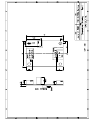
Analog Resistive Touch Screen Controller
TSC-10/RSA Series User’s Guide
TSC-10/RSA Series User’s Guide
Table of Contents
1. Product Overview .................................................................................................................. 2
1-1. Products Applicable .......................................................................................................... 2
1-2. Product Names ................................................................................................................. 2
1-3. Overview ............................................................................................................................ 2
1-4. Peripheral Composition Overview.................................................................................... 3
2. Specifications ......................................................................................................................... 4
3. Connector................................................................................................................................ 5
3-1. Explanation of a connector terminal ............................................................................... 5
3-2. The mounted connector ................................................................................................... 5
4. Operation modes and functions......................................................................................... 6
4-1. Outline................................................................................................................................ 6
4-2. Initialization mode and idle mode ................................................................................... 8
4-3. Coordinate data mode.................................................................................................... 10
4-4. Calibration data setup mode ......................................................................................... 13
4-5. Calibration data read mode........................................................................................... 17
4-6. Calibration data mode .................................................................................................... 18
4-7. STOP mode .................................................................................................................... 21
4-8. Panel ID/mode information acquisition.......................................................................... 22
4-9. Mode list.......................................................................................................................... 23
4-10. Command list ................................................................................................................ 23
5. Changes & Improvements.................................................................................................. 24
5-1. Version History................................................................................................................ 24
6. Warranty ................................................................................................................................ 25
6-1. Warranty Period .............................................................................................................. 25
6-2. Warranty Target .............................................................................................................. 25
6-3. Warranty Exceptions....................................................................................................... 25
7. Precautions for Use ............................................................................................................ 26
7-1. General Handling ............................................................................................................ 26
7-2. Others .............................................................................................................................. 26
Dimensional Drawing
1
Rev.1.4 ©2004-2005 DMC Co., Ltd.
TSC-10/RSA Series User’s Guide
1. Product Overview
1-1. Products Applicable
This specification is applicable to TSC-10/RSA and TSC-10/RSA-E.
1-2. Product Names
Product Name
TSC-10/RSA
TSC-10/RSA-E
Description
TSC-10/IC installed touch screen controller board.
TSC-10/IC installed touch screen controller
EEPROM.
board
with
1-3. Overview
TSC-10/RSA and TSC-10/RSA-E are a touch screen controller board that performs an A/D conversion of
an analog signal of a resistive touch screen, and transmits the coordinate data to the host in a 10-bit resolution serial correspondence at 9600bps. TSC-10/RSA and TSC-10/RSA-E can be used for various applications for its functions including the power saving mode, seven sampling speed settings (max. 150p/s *1),
two external switch connections, and automatic calibration data loading with an external EEPROM.
§
TSC-10/RSA
TSC-10/RSA dispenses a need to newly design the peripheral circuits, and can easily
be used by connecting to the touch screen and the host. Using the driver software *2
enables the mouse emulation on various operation systems and dispenses the need to
newly design the controller software.
§
TSC-10/RSA-E An EEPROM installed version of TSC-10/RSA. The calibration data can be stored in
the EEPROM and automatically read after power-on.
*1: 150 transmissions of coordinate data per second.
*2: Please contact the local sales representatives for software availability.
2
Rev.1.4 ©2004-2005 DMC Co., Ltd.
TSC-10/RSA Series User’s Guide
1-4. Peripheral Composition Overview
A resistive touch screen is operated by resistance sensitive system between two layers such as film or
glass. Two pieces of transparent materials with conductive coating are placed in the same direction as
two electrodes face each other. The touch screen is activated when these transparent conductive layers
are pressed to contact each other with a finger or a pen. The one of these conductive layers functions as
an X-coordinates electric circuits and the other as a Y-coordinates circuits.
To measure the
X-coordinates TSC-10/RSA and TSC-10/RSA-E supplies voltage, Vcc to the one of X-coordinates electrodes with GND to the other. When the touch screen is pressed under this environment the voltage of
the X-coordinates resistance is detected by the Y-coordinates electrode (A_in) at the input point (x1),
where the X-Y coordinate resistance layers make contact. The detected voltage in supply side is higher
than the GND side, which means ‘A_in’=Vcc at the point ‘E’ and ‘A_in’=0(*1) at the point ‘A’.
TSC-10/RSA and TSC-10/RSA-E calculates coordinates data starting from A/D conversion of the ‘A_in’
voltage. The Y-coordinates is measured in the same way. By repeating this process alternately, coordinate value at the input point is determined.
(*1) Excluding the loss in the controller circuits and touch screen. Actual detected voltage should be
lower than ‘Vcc - GND’ because of loss happened in the circuitry.
Vcc
X-resistive-layer (reverse side)
Touch
xl
X electrode
(reverse side)
Y-resistive-layer
Y electrode
A_in
E
D
C
B
Vcc = 5.0V
xl
A_in
Output Data
A
B
C
D
E
0V
1.25V
2.5V
3.75V
5V
0000h (Min.)
00FFh
01FFh
02FFh
03FFh (Max.)
A
(TSC-10/RSA, TSC-10/RSA-E)
Vcc
xl
X-resistive-layer
(TSC-10/IC)
A_in
Y-resistive-layer
E
D
C
B
(RS-232C)
Touch
(Touch Screen)
To host
A
3
Rev.1.4 ©2004-2005 DMC Co., Ltd.
TSC-10/RSA Series User’s Guide
2. Specifications
General Specifications
Item
Rating
TSC-10/RSA
TSC-10/RSA-E
TSC-10/RSA
Storing Temp.
TSC-10/RSA-E
TSC-10/RSA
Supply Voltage
TSC-10/RSA-E
TSC-10/RSA
Supply Current
TSC-10/RSA-E
Format
Transfer Rate
Correspondence
Data Format
Stop Bit
Parity
Frequency
TSC-10/RSA
Dimension
TSC-10/RSA-E
-20°C to +75°C
(No dew condensation)
-20°C to +85°C
(No dew condensation)
Operating Temp.
Remarks
DC 4.1V to 5.5V
15mA
Asynchronous Serial
9600bps
8bit
1bit
None
6MHz
Vin=5.0V, At sampling Rate = 50p/s
when touch screen is activated
Fixed value
6MHz fixed
30 x 40 mm
8mm
Max height of components
(2mm)
When EEPROM mounted.
The backside of a board.
Performance Specifications
Description
Coordinate Output Rate (point/sec)
Rating
(1) point mode
(2) 30p/s (3) 50p/s
(4) 80p/s (5) 100p/s
Note
Default: 50pps with DMC original
driver software.
(6) 130p/s (7) 150p/s
Coordinate Resolution
Linearity Error
Input Response Time
10bit (1024 x 1024)
The value will be lower in the active
area of the touch screen
±3 LSB
Maximum value at 50pps.
23ms
When using the coordinate data mode
4
Rev.1.4 ©2004-2005 DMC Co., Ltd.
TSC-10/RSA Series User’s Guide
3. Connector
3-1. Explanation of a connector terminal
CN
Terminal
Name
Function
CN1
1
2
3
4
XL
YU
XR
YD
Touch
Touch
Touch
Touch
screen
screen
screen
screen
Input
Input
Input
Input
XL
YU
XR
YD
(Open
(Open
(Open
(Open
if
if
if
if
CN2
CN2
CN2
CN2
is
is
is
is
used)
used)
used)
used)
CN2
1
2
3
4
XL
YU
XR
YD
Touch
Touch
Touch
Touch
screen
screen
screen
screen
Input
Input
Input
Input
XL
YU
XR
YD
(Open
(Open
(Open
(Open
if
if
if
if
CN1
CN1
CN1
CN1
is
is
is
is
used)
used)
used)
used)
CN3
1
2
3
4
5
Dout
Din
GND
Vin
Vin
RS-232C
RS-232C
RS-232C
RS-232C
RS-232C
Data Output
Data Input
GND
Power (Open if power is supplied from CN5)
Power (Open if power is supplied from CN5)
CN4
1
2
3
4
5
Dout
Din
GND
Vin
Vin
RS-232C
RS-232C
RS-232C
RS-232C
RS-232C
Data Output
Data Input
GND
Power (Open if power is supplied from CN5)
Power (Open if power is supplied from CN5)
1
Vin
Power (+5V) (Open if power is supplied from CN3 or CN4)
2
GND
GND (Open if power is supplied from CN3 or CN4)
Either CN1 or CN2 is mounted.
CN5
Either CN3 or CN4 is mounted.
3-2. The mounted connector
CN
P/N
Manufacturer
CN1
00-8370-049-000-800
KYOCERA ELCO CORPORATION
CN3
S5B-PH-K-S
J.S.T. Mfg Co., Ltd
CN5
S2B-PH-K-S
J.S.T. Mfg Co., Ltd
5
Rev.1.4 ©2004-2005 DMC Co., Ltd.
TSC-10/RSA Series User’s Guide
4. Operation modes and functions
4-1. Outline
TSC-10/IC enters the Initialization mode immediately after it is turned on or reset. In this mode,
no setting is made and each mode shall be set. To transition to the available state, select the
coordinate output rate and coordinate output mode and set the operation mode.
§
Initialization mode
By either power supply ON or hardware reset/software reset, the internal initial setting is perfor
med. In the serial scheme, communication with host is available. In USB scheme, device recogn
ition process ends. In this mode, both serial and USB schemes receive a coordinate output rate
command and transition to the idle mode.
After hardware reset, it takes 500ms to transition to the initialization mode.
In using the EEPROM, EEPROM data is read in this mode.
§
Idle mode
TSC-10/IC enters this operation waiting mode after the coordinate output rate setting command is received. Transition to each mode takes place in this mode.
§
Coordinate data mode
In this mode, analog data obtained from touch screen is output as coordinate data with 10 bit resolution
without any calibration.
This mode starts in the “idle mode“ by receiving the coordinate data send start command, and returns
to “idle mode” again after receiving the coordinate data send end command. By receiving reset command, it transitions to the ”initialization mode“.
This mode is used when host driver implements the calibration function, and also when necessary data
is obtained in the calibration data setup mode.
§
Calibration data setup mode
In this mode, calibration data used in “calibration data mode“ is set. Transition to this mode takes place
when the setup mode start command is received in the idle mode. Select an appropriate calibration
point among:
- X=2, Y=2 (four point calibration)
- X=3, Y=3 (nine point calibration) and
- X=2, Y=2 (four point calibration) plus one center position (five point calibration)
When this mode ends, calibration data is entered to EEPROM.
§
Calibration data read mode
In this mode, setup data is read out from EEPROM if in using EEPROM, data set in the ”calibration
data setup mode“ is stored to EEPROM. It is used if setting data is to be confirmed. Transition to this
mode takes place and calibration data is output to the host if in the idle mode, calibration data read
command is received.
§
Calibration data mode
In this mode, individual difference and loss in the touch screen are corrected and coordinate value
output is performed. Using calibration data set in the ”calibration data setup mode“, touch screen input
point and indicator’s cursor display position can be matched.
In using this mode, the host driver needs no calibration function.
Using “calibration data setup mode“ setting value to set the coordinate data maximum value, maximum
value can be limited to 10bits or less.
This mode starts when in the idle mode, any ”calibration data send start command“ is received, and
returns to the idle mode when receiving the calibration data send end command. When receiving the
reset command, this mode transitions to the initialization mode.
6
Rev.1.4 ©2004-2005 DMC Co., Ltd.
TSC-10/RSA Series User’s Guide
§
STOP mode
This mode is enabled only in the serial communication. This mode starts when in the idle mode, STOP
mode start command is received. This mode stops ceramic vibrator’s vibration and enters the power
saving mode where the operation stops. By hardware reset, this mode transitions to the initialization
mode. By receiving [00h] (null command) from host, the power saving mode ends and transitions to the
idle mode.
§
Power-save mode
This mode is only enabled in the serial communication. If in the coordinate data mode transitioned from
[01h] or the calibration data mode transitioned from [0Ah], there are no inputs on the touch screen for
20 samplings, the ceramic vibrator stops its vibration and enters the power saving mode where no operations are taken. By inputting the touch screen or receiving a command from host, power saving
mode is released and the transition to “coordinate data mode “ or ”calibration data mode“ takes place.
7
Rev.1.4 ©2004-2005 DMC Co., Ltd.
TSC-10/RSA Series User’s Guide
4-2. Initialization mode and idle mode
After the power up or hardware reset, internal initialization setting is performed (about 500ms)
and the transition to the initialization mode occurs, where waiting for the communication with
host. In this mode, if external EEPROM is used, EEPROM data is read.
In the initialization mode, use the coordinate output rate setting command to set the interval for
sending a coordinate. Where, touch screen connection state and EEPROM data are checked
and in either normal or abnormal case, data representing each state is output to the host. Thus,
the initialization mode transitions to the idle mode. Transition to each mode occurs from the idle
mode. Once coordinate output rate is set with transition to the idle mode, coordinate output rate
setting may be available again.
If in either idle mode, coordinate data mode or calibration data mode, reset command is received, transition to the initialization mode occurs. Where, after receiving the reset command,
internal processing takes a time, be sure to issue subsequent commands after 6ms or more is
elapsed.
§
Mode transition
Host
[12h]
[S_Rate]
[06h/15h]
TSC-10/IC
Idle mode
Initialization mode
Internal initial setting
Initialization
(About 500ms)
Power-on
*After application of power (hardware-reset), to tell a host computer having changed
into the state where TSC-10/IC can communicate, it outputs “12h”. But, “12h” is not
outputted when software-reset is carried out.
§
Coordinate output rate setting command (S_Rate)
Mode
Stream
Point
Sampling
30p/s
50p/s
80p/s
100p/s
130p/s
150p/s
Once when
touched
Command
05h+40h
05h+41h
05h+42h
05h+43h
05h+44h
05h+45h
Description
In the coordinate (calibration) data mode, no pen-up data
is output.
05h+50h
8
Rev.1.4 ©2004-2005 DMC Co., Ltd.
TSC-10/RSA Series User’s Guide
§
Response command (no EEPROM is used)
State
Normal
Abnormal
§
Byte
width
Response command
06h (ACK)
15h (NAK)
1 byte
1 byte
Description of mode
Touch screen connection normal
Touch screen not connected
Response command (EEPROM is used)
State
Normal
Byte
width
Response command
06h (ACK)
1 byte
Description of mode
Touch screen connection, EEPROM data
normal
15h (NAK) +
detail code
bit0=1 (01h)
EEPROM data empty
Abnormal
2
bit1=1 (02h)
EEPROM data abnormal
bytes
bit2=1 (04h)
EEPROM write error
bit3=1 (08h)
Touch screen not connected
* If, in the initialization mode, coordinate output rate setting is performed, EEPROM is checked if
data is present or not. Thus, error code only refers to EEPROM data empty (detail code: 01h).
In the idle mode, run the calibration data setup mode. After EEPROM data abnormal or EEPRO
M write error occurs, set the coordinate output rate, error code is output, indicating EEPROM d
ata abnormal or EEPROM write error. Error flag can be deleted by either hardware reset or soft
ware reset.
9
Rev.1.4 ©2004-2005 DMC Co., Ltd.
TSC-10/RSA Series User’s Guide
4-3. Coordinate data mode
Analog data input from analog touch screen is A/D converted for calculating the coordinate data,
which is output in this mode.
This mode is used if calibration is made in the host driver. In using the external EEPROM in the
calibration data mode, previously performed ”calibration data setup mode“ needs raw data,
which is obtained in this mode.
From the idle mode, this mode starts by receiving either command of coordinate data send start
1 – 3, and returns to the idle mode by receiving the coordinate data send end command. By
receiving “reset” command, the mode transition to the initialization mode.
At the touch screen input (when a finger or pen touches on the touch screen), coordinate data,
including pen-down ID indicating that touch screen is input, is output to the host with coordinate
output rate interval. If the touch screen input ends (when a finger or pen leaves the touch
screen), in the serial mode, pen-up ID of 1byte is output, or in the USB mode, coordinate data
including pen-up ID is output (excluding the point mode).
§
Mode transition
Host
[01h/21h/31h]
TSC-10/IC
Coordinate
data
[02h]
[06h]
Coordinate data mode
Idle mode
§
Command and each mode function
Mode name
Command
Coordinate
start 1
data
send
Coordinate
start 2
data
send
Coordinate
start 3
data
send
Coordinate
end
data
send
01h
21h
31h
02h
Function
Pen-down: Coordinate data including pen-down ID is output with the
coordinate output rate interval.
Pen-up:
Pen-up ID is output one time.
No input: If there are no inputs for 20 sampling times, transition to the
power-save mode occurs.
Pen-down: Coordinate data including pen-down ID is output with the
coordinate output rate interval.
Pen-up:
Coordinate data including pen-up ID is output with the coordinate output rate interval.
No input: No transition to the power-save mode.
Pen-down: Coordinate data including pen-down ID is output with the
coordinate output rate interval.
Pen-up:
Pen-up ID is output one time.
No input: No transition to the power-save mode.
Coordinate data mode ends and transition to the idle mode occurs.
10
Rev.1.4 ©2004-2005 DMC Co., Ltd.
TSC-10/RSA Series User’s Guide
§
Coordinate format
Pen-down data
Meaning
Byte 0
Byte 1
Byte 2
Byte 3
Byte 4
Pen Down ID
X Upper
X Lower
Y Upper
Y Lower
b7
b6
b5
b4
b3
b2
b1
b0
SW0
0
X7
0
Y7
SW1
0
X6
0
Y6
0
0
X5
0
Y5
1
0
X4
0
Y4
0
0
X3
0
Y3
0
0
X2
0
Y2
0
X9
X1
Y9
Y1
1
X8
X0
Y8
Y0
b7
b6
b5
b4
b3
b2
b1
b0
SW0
SW1
0
1
0
0
0
0
Pen-up data
Meaning
Byte 0
Pen Up ID
List of Pen-down ID (pen-down data Byte 0) List of pen-up ID (pen-up data Byte 0)
ID
11h
51h
91h
D1h
§
SW0
0
0
1
1
SW1
0
1
0
1
ID
10h
50h
90h
D0h
SW0
0
0
1
1
SW1
0
1
0
1
Example of Data (transmission starts at receiving [01h] or [31h]) (Where X = 0374h and Y = 01A9h)
PD Data
PD Data
PD Data
PD Data
PU Data
t
Input ON
PD ID
Input OFF
X Upper
X Lower
Y Upper
01h
Bit
Data
7
0
6
0
5
0
4
0
3
0
2
0
Y Lower
A9h
1
0
Bit
Data
0
1
7
1
6
0
5
1
4
0
3
1
2
0
1
0
0
1
Immediately after Pen-up, if the first sampling is pen-up, immediately preceding pen-down data
is output. If second time sampling is pen-up, none is output. If third time sampling is pen-up,
pen-up data is output once.
11
Rev.1.4 ©2004-2005 DMC Co., Ltd.
TSC-10/RSA Series User’s Guide
§ Example of data (transmission starts at receiving [21h])
PU Data
PU Data
PD Data
PD Data
PD Data
PD Data
PU Data
PU Data
t
Input ON
Input OFF
*: Immediately after Pen-up, if the first sampling is pen-up, immediately preceding pen-down data is output. If second time sampling is pen-up, none is output. If third time sampling is pen-up, pen-up data is
output. Thereafter, pen-up data is output at the coordinate output rate interval. Coordinate value at
pen-up always takes same coordinate value as the last pen-down data. After the coordinate data mode
transition until the first pen-down, 0000h is output.
§
Power-save mode
“Coordinate data send start 1” command (01h) activates the transition to the coordinate data mode. If
for 20 sampling times (Example: 100p/s = 200ms), no touch screen is input, ceramic vibrator’s vibration
stops and the operation ends by entering the power saving mode. Input to the touch screen (analog
data input) or command reception from host will release this mode, and after the vibration stabilization
time elapses (6ms), the operation returns to the coordinate data mode.
If TSC-10/IC receives ”coordinate data mode end” command (02h), this mode shall be released. Thus,
within 20 sampling times in the condition where either command (or touch screen input) releases this
mode, [02h] shall be received.
Host
Coordinate data
[Command]
[02h]
[06h]
TSC-10/IC
Idle mode
Coordinate data mode
Power save mode
Vibration
stabilization time
20 samplings
(6ms)
12
20 samplings
Rev.1.4 ©2004-2005 DMC Co., Ltd.
TSC-10/RSA Series User’s Guide
Correction point
Touch screen
4-4. Calibration data setup mode
On the touch screen, due to offset and rotation
caused by shifted pasting on touch screen and
elements such as losses from surrounding cirDefine coordinate
cuit, touch screen input point and indicator
values
coordinate indication may be unmatched with
corresponding to
correction points
each other if A/D conversion value is output as
coordinate value.
Y coordinate
To resolve this, TSC-10/IC defines in advance
any point on touch screen as a calibration point,
where the calibration point’s raw coordinate
LCD display area
(A/D conversion value) and calibration coordinate value to be output to the host after calibration, and in the actual operation, from defined
X coordinate
coordinate value, corresponding calibration
coordinate value of touch screen input point’s raw coordinate is calculated and output to the
host (calibration data mode).
In this mode, data required for calibration is set up. Number of maximum calibration points is
nine in total with X = 3 and Y = 3.
For setup in this mode, coordinates of calibration points in the coordinate data mode shall be
obtained in advance.
By receiving setup mode start command in the idle mode, the operation transitions to this mode
and after setup processing ends, data corresponding to the normal end or abnormal end is output to the host, then the operation returns to the idle mode.
If the external EEPROM is used, this processing writes data to EEPROM.
§
Mode transition
Host
[0Dh/0Eh]
TSC-10/IC
Number of
points
Coordinate
data
Maximum
value
[06h/15h]
Coordination data setup
Idle mode
300ms
* Within 300 msec after the last data (calibration data maximum value) is received and until the operation
transitions to the idle mode, no command reception is available.
§
Command
Mode
Command
Setup mode start 1
0Dh
Setup mode start 2
0Eh
Function
Normal calibration (Specify the number of calibration
points in X and Y each)
Five point calibration (four points at touch screen’s 4 corners and one point at the center)
13
Rev.1.4 ©2004-2005 DMC Co., Ltd.
TSC-10/RSA Series User’s Guide
§
Response command (no EEPROM is used)
State
Normal
Abnormal
§
Response command
06h (ACK)
15h (NAK)
Bit
width
1 byte
1 byte
Mode description
Setting completed
Parameter abnormal
Response command (EEPROM is used)
State
Normal
Abnormal
Response command
06h (ACK)
15h (NAK) + detail code
bit1=1 (02h)
bit2=1 (04h)
Bit
width
Mode description
1 byte
EEPROM write normal
2
bytes
EEPROM data abnormal
EEPROM write error
14
Rev.1.4 ©2004-2005 DMC Co., Ltd.
TSC-10/RSA Series User’s Guide
§
Setup procedure
1.
Define calibration point and number of calibration points and display a cross mark and
arrow on indicator to obtain coordinate values at the calibration point in the coordinate
data mode.
2. Transmit command [0Dh/0Eh] to TSC-10/IC (transition to ”calibration data setup mode“),
and input data according to the calibration data setting format. After all data are input,
ACK/NAK is output to the host and the operation automatically transitions to the idle
mode.
Idle mode
Coordinate data mode
Retrieve raw data of
correction points
Idle mode
Coordination data setup
Input raw data of correction
points, correction data and
maximum coordinate value
Idle mode
§
Calibration data setting format
1. Number of points: X direction = 3, Y direction = 3 (Maximum coordinate value: 0000h 03FFh)
Correction point (origin at top left)
0Dh
1 byte
P00
P01
P02
03h
1 byte
P10
P11
P12
03h
1 byte
P20
P21
P22
P00 coordinate value
8 byte
Upper layer
1 byte
Lower layer
1 byte
X raw coordinate value
P01 coordinate value
8 byte
P02 coordinate value
8 byte
Y raw coordinate value
P10 coordinate value
2 byte
2 byte
X correction
coordinate value
2 byte
Y correction
coordinate value
2 byte
8 byte
P12 coordinate value
8 byte
P22 coordinate value
8 byte
Upper layer
1 byte
X Maximum coordinate value
2 byte
Lower layer
1 byte
Y Maximum coordinate value
2 byte
15
Rev.1.4 ©2004-2005 DMC Co., Ltd.
TSC-10/RSA Series User’s Guide
2. Number of points: X = 2, Y = 2 and 5 point
X=2, Y=2 (Maximum coordinate value: X=03FFh, Y=03FFh)
5 Point (Maximum coordinate value: X=03FFh, Y=03FFh)
Correction point (origin: top left)
Correction point (origin: top left)
P00
P01
P00
P01
PCT
P10
P11
P11
0Dh
1 byte
0Eh
1 byte
02h
1 byte
P00 Coordinate value
8 byte
02h
1 byte
P01 Coordinate value
8 byte
P00 Coordinate value
8 byte
P10 Coordinate value
8 byte
P01 Coordinate value
8 byte
P11 Coordinate value
8 byte
P10 Coordinate value
8 byte
PCT Coordinate value
8 byte
P11 Coordinate value
X Maximum coordinate
value
Y Maximum coordinate
value
§
P10
X Maximum coordinate
8 byte
value
03h
1 byte
FFh
1 byte
2 byte
Y Maximum coordinate
2 byte
03h
1 byte
FFh
1 byte
8 byte
2 byte
* PCT is at the center of indicator.
Handling outside the coordinate range
If a portion only of the touch screen is to be operated, some calibration may cause the touch screen
input points even inside the input area to be located outside the maximum coordinate point (or minimum coordinate point). Where, touch screen input is not disabled and the following data is transmitted.
Minimum coordinate value (X = 00 00, Y= 00 00)
X: 00 00
Y: 00 00
X: Coordinate
Y: 00 00
X: 00 00
Y: Coordinate
X: 00 00
Y: 03 FF
X: 03 FF
Y: 00 00
Input area
X: 03 FF
Y: Coordinate
X: Coordinate
Y: 03 FF
X: 03 FF
Y: 03 FF
Touch screen outer
frame
Maximum coordinate value (X = 03 FF, Y= 03 FF)
16
Rev.1.4 ©2004-2005 DMC Co., Ltd.
TSC-10/RSA Series User’s Guide
4-5. Calibration data read mode
In this mode, data set in the calibration data setup mode is read from EEPROM, used to check
the parameter setting.
This mode is executed from idle mode to transmit the stored calibration data, then the operation
automatically transitions to idle mode. If no calibration data is stored in EEPROM, none is output.
Note) In this mode, number of calibration points is treated with 25 point (X=5, Y=5) format, since FIT-10/IC, a touch
screen controller IC, supports the maximum 25 point calibration function and protocol compatibility in the serial mode
shall be kept with FIT-10/IC. Coordinate data of calibration points not supported by TSC-10/IC are all output with 0000h.
§ Mode transition
Host
[1Dh]
TSC-10/IC
Number of
points
Coordinate
data
Maximum
Correction data read mode
Idle mode
§ Calibration data send format
In the idle mode, if 1Dh is received, calibration data is sent to the host with the following format.
In the calibration data setup mode, if setup mode start 2 (0Eh) is used, data is converted to nine
point calibration (X=3, Y=3) for setup mode start 1 (0Dh) then stored, thus if output to the host, it
uses nine point calibration format.
Correction points (5×5)
X_P
P00 P01 P02 P03 P04
1 byte
P10 P11 P12 P13 P14
P20 P21 P22 P23 P24
Y_P
1 byte
P00 coordinate value
8 byte
P01 coordinate value
8 byte
P02 coordinate value
8 byte
P43 coordinate value
8 byte
P30 P31 P32 P33 P34
P40 P41 P42 P43 P44
P44 coordinate value
8 byte
X Maximum coordinate
value
2 byte
Upper layer
Lower layer
Y Maximum coordinate
value
1 byte
1 byte
2 byte
17
X raw coordinate value
2 byte
Y raw coordinate value
2 byte
X correction
coordinate value
2 byte
Y correction
coordinate value
2 byte
Upper layer
1 byte
Lower layer
1 byte
Rev.1.4 ©2004-2005 DMC Co., Ltd.
TSC-10/RSA Series User’s Guide
4-6. Calibration data mode
In this mode, based on calibration value obtained from the calibration data setup mode, coordinate value is corrected and output. In this mode, maximum output coordinate value can be limited.
From the idle mode, this mode starts by receiving either command of coordinate data send start
1 – 3, and returns to the idle mode by receiving the calibration data send end command. By receiving “reset” command, the mode transition to the initialization mode.
At the touch screen input (when a finger or pen touches on the touch screen), coordinate data,
including pen-down ID indicating that touch screen is input, is output to the host with coordinate
output rate interval. If the touch screen input ends (when a finger or pen leaves the touch
screen), in the serial mode, pen-up ID of 1byte is output, or in the USB mode, coordinate data
including pen-up ID is output (excluding the point mode).
§ Mode transition
Host
Coordinate
data
[0Ah/2Ah/3Ah]
[0Bh]
[06h]
TSC-10/IC
Correction data mode
Idle mode
§
Command and mode function
Mode name
Command
Calibration data send
start 1
0Ah
Calibration data send
start 2
2Ah
Calibration data send
start 3
3Ah
Calibration data send
end
0Bh
Function
Pen-down: Coordinate data including pen-down ID is output with the
coordinate output rate interval.
Pen-up:
Pen-up ID is output one time.
No input:
If there are no inputs for 20 sampling times, transition to the
power-save mode occurs.
Pen-down: Coordinate data including pen-down ID is output with the
coordinate output rate interval.
Pen-up:
Coordinate data including pen-up ID is output with the coordinate output rate interval.
No input:
No transition to the power-save mode.
Pen-down: Coordinate data including pen-down ID is output with the
coordinate output rate interval.
Pen-up:
Pen-up ID is output one time.
No input:
No transition to the power-save mode.
Coordinate data mode ends and transition to the idle mode occurs.
18
Rev.1.4 ©2004-2005 DMC Co., Ltd.
TSC-10/RSA Series User’s Guide
§ Power-save mode
“Coordinate data send start 1” command (0Ah) activates the transition to the coordinate data mode. If
for 20 sampling times, no touch screen is input, ceramic vibrator’s vibration stops and the operation
ends by entering the power saving mode. Input to the touch screen (analog data input) or command
reception from host will release this mode, and after the vibration stabilization time elapses (6ms), the
operation returns to the calibration data mode.
If TSC-10/IC receives “calibration data mode end” command (0Bh), this mode shall be released. Thus,
within 20 sampling times in the condition where either command (or touch screen input) releases this
mode, [0Bh] shall be received.
Host
Coordinate data
[Command]
[0Bh]
[06h]
TSC-10/IC
Idle mode
Correction data mode
Power save mode
Vibration stabi
lization time
(6ms)
20 samplings
19
20 samplings
Rev.1.4 ©2004-2005 DMC Co., Ltd.
TSC-10/RSA Series User’s Guide
§
Data description
Pen-down data
Meaning
Byte 0
Byte 1
Byte 2
Byte 3
Byte 4
Pen Down ID
X Upper
X Lower
Y Upper
Y Lower
b7
b6
b5
b4
b3
b2
b1
b0
SW0
0
X7
0
Y7
SW1
0
X6
0
Y6
0
0
X5
0
Y5
1
0
X4
0
Y4
0
0
X3
0
Y3
0
0
X2
0
Y2
0
X9
X1
Y9
Y1
1
X8
X0
Y8
Y0
b7
b6
b5
b4
b3
b2
b1
b0
SW0
SW1
0
1
0
0
0
0
Pen-up data
Meaning
Byte 0
Pen Up ID
List of pen-down ID (pen-down data Byte 0)
ID
11h
51h
91h
D1h
§
SW0
0
0
1
1
SW1
0
1
0
1
List of pen-up ID (pen-up data Byte 0)
ID
10h
50h
90h
D0h
SW0
0
0
1
1
SW1
0
1
0
1
Example of data (transmission starts by receiving [0Ah] or [3Ah]) (Where, X = 0374h and Y = 01A9h)
PD Data
PD Data
PD Data
PD Data
PU Data
t
Input ON
PD ID
Input OFF
X Upper
X Lower
Y Upper
01h
Bit
Data
7
0
6
0
5
0
4
0
3
0
2
0
Y Lower
A9h
1
0
Bit
Data
0
1
7
1
6
0
5
1
4
0
3
1
2
0
1
0
0
1
Immediately after Pen-up, if the first sampling is pen-up, immediately preceding pen-down data
is output. If second time sampling is pen-up, none is output. If third time sampling is pen-up,
pen-up data is output once.
20
Rev.1.4 ©2004-2005 DMC Co., Ltd.
TSC-10/RSA Series User’s Guide
§
Example of data ([transmission starts by receiving 2Ah])
PU Data
PU Data
PD Data
PD Data
PD Data
PD Data
PU Data
PU Data
t
Input ON
Input OFF
*: Immediately after Pen-up, if the first sampling is pen-up, immediately preceding pen-down data is output. If second time sampling is pen-up, none is output. If third time sampling is pen-up, pen-up data is
output. Thereafter, pen-up data is output at the coordinate output rate interval. Coordinate value at
pen-up always takes same coordinate value as the last pen-down data. After the coordinate data mode
transition until the first pen-down, 0000h is output.
4-7. STOP mode
This mode starts by receiving [0Fh] (STOP mode start command) in the idle mode. In this mode,
ceramic vibrator’s vibration stops and operation also stops in the power consumption mode. If
hardware is reset, the operation transitions from this mode to initialization mode. By receiving
[00h] (null command) from host, CPU STOP mode is released and after vibration stabilize waiting time (6ms) is elapsed, the operation enters idle mode.
This mode operates in the serial mode only.
Host
TSC-10/IC
[0Fh]
[00h]
Idle mode
STOP mode
Vibration stabilization
time
(6ms)
21
Rev.1.4 ©2004-2005 DMC Co., Ltd.
TSC-10/RSA Series User’s Guide
4-8. Panel ID/mode information acquisition
This function is used to obtain panel ID in the USB mode, current transition mode, and
used/unused status information of SW0, SW1 and EEPROM. It is used to know the current operation status.
This function is available in initialization mode, idle mode, coordinate data mode and calibration
data mode.
Panel ID is enabled by releasing hardware reset. Thus, if, after hardware reset, pin information
was changed, restart the power or reset hardware to enable the setting.
Mode information always outputs the last command. Therefore, be sure that even in the idle
mode, output data differs per last command.
This function is used to check current mode, and used/unused status of SW0, SW1 and
EEPROM. Pin number 3 (SEL1) setting allows you to obtain the panel ID information, though
this function is unavailable in serial mode in terms of objectives of panel ID.
§
§
Command
Command
Output data
15h
2 bytes
Command enabled mode
Initialization mode
Idle mode
Coordinate (calibration) data mode
Description of output data
Data content: Byte 1 (Upper bits: b15 - b8) includes the transition mode information, and byte 2
(lower bits: b7 - b0) outputs the setting information. In the serial mode, b4 is fixed to “0”.
Bit
Bit information
b0
Fixed to “0”
b1
Panel ID (pin number 3)
“1” = PID 1
“0” = PID 0
b2
SW1 (pin number 28)
“1” = SW ON
“0” = SW OFF
b3
SW0 (pin number 29)
“1” = SW ON
“0” = SW OFF
b4
USB/RS (pin number 25)
“1” = USB
“0” = RS
b5
Fixed to “0”
b6
Fixed to “0”
SEL4/EEP-CS (pin number “1” = EEPROM Un“0” = EEPROM Used
b7
16)
used
Transition mode information
00h: initialization mode
05h: idle mode (immediately preceding command sets the coordinate output
rate)
01h: coordinate data mode start 1
21h: coordinate data mode start 2
b8-15
31h: coordinate data mode start 3
02h: idle mode (immediately preceding command is 02h)
0Ah: calibration data mode start 1
2Ah: calibration data mode start 2
3Ah: calibration data mode start 3
0Bh: idle mode (immediately preceding command is 0Bh)
22
Rev.1.4 ©2004-2005 DMC Co., Ltd.
TSC-10/RSA Series User’s Guide
4-9. Mode list
Power ON
Power save mode
Touch/command
Touch/command
20 samplings
20 samplings
[55h]
Coordinate data mode
Initialization mode
[55h]
Correction data mode
[05h]+[S_Rate]
[02h]
[01h/21h/31h]
[55h]
[0Bh]
[0Ah/2Ah/3Ah]
Idle mode
[Hardware
is reset]
[0Dh/0Eh]
[00h]
Read completed
STOP mode
Correction data
read mode
Setting completed
Correction data
setup mode
[1Dh]
[0Fh]
4-10. Command list
Command
00h
05h
01h
21h
31h
02h
0Ah
2Ah
3Ah
0Bh
0Dh
0Eh
1Dh
0Fh
55h
15h
§
Accompanying
command (byte)
1
-
ACK/NAK
ACK/NAK
ACK
ACK
ACK/NAK
ACK/NAK
ACK
ACK
-
Name
Null
Coordinate output rate setting
Coordinate data send start 1
Coordinate data send start 2
Coordinate data send start 3
Coordinate data send end
Calibration data send start 1
Calibration data send start 2
Calibration data send start 3
Calibration data send end
Calibration data setup mode start 1
Calibration data setup mode start 2
Calibration data read
STOP mode start
Reset
Panel ID/ mode information retrieval
Wait after issuing command
After issuing the following commands, wait as specified before issuing the next command.
Reset
Calibration data setup (1)
Calibration data setup (2)
Serial
command
55h
0Dh
0Eh
USB command
(bRequest)
55h
0Dh
0Eh
Calibration data read
1Dh
1Dh
Command name
23
Wait time
6ms
300ms after issuing last data
300ms after issuing last data
0ms after reading last data (no wait required)
Rev.1.4 ©2004-2005 DMC Co., Ltd.
TSC-10/RSA Series User’s Guide
5. Changes & Improvements
5-1. Version History
§ TSC-10/RSA
Ver1.0 (November 17, 2003)
First Edition.
Ver1.1 (December 15, 2003)
Mounting connector notation addition.
Ver1.2 (March 8, 2004)
Connector (CN1) change.
Ver1.3 (June 20, 2005)
“4-8. Panel ID/Mode information acquisition” addition.
Ver1.4 (October 31, 2005)
6.”Warranty” is added.
24
Rev.1.4 ©2004-2005 DMC Co., Ltd.
TSC-10/RSA Series User’s Guide
6. Warranty
6-1. Warranty Period
§ The warranty period is limited to 1 year from the date of shipping. The warranty for the initial defection
such as appearance defection is limited to 1 month.
§ Any defected parts under proper use will be examined by the supplier and replaced by the new parts if
the defection is considered to be caused by the supplier.
§ The replacement is subject to be included in the next lot.
6-2. Warranty Target
§ The warranty only covers the product itself and does not cover any damage to others caused by using
this product. Onsite repair or replacement is not supported.
§ We will do our best for delivery problem and product defections, but the warranty for the production line
is not covered.
6-3. Warranty Exceptions
Following conditions are not covered with the warranty and subject to charge.
§ Any malfunctions and damages during transportation and transfer by the user.
§ Any malfunctions and damages caused by a natural disaster or a fire.
§ Any malfunctions and damages caused by static electricity
§ Any malfunctions and damages caused by the failure of the associated equipment.
§ If the product is remodeled, disassembled or repaired by the user.
§ If the product is glued onto the equipment and uninstalled.
§ Any malfunctions and damages caused by an improper usage and handling against the specifications
and notes.
25
Rev.1.4 ©2004-2005 DMC Co., Ltd.
TSC-10/RSA Series User’s Guide
7. Precautions for Use
7-1. General Handling
§
Keep the product away from any conductive objects while in use.
§
Do not touch the conductive part of the product to avoid being damaged by the electrostatic discharge.
Follow the proper procedure for handling.
§
Keep the product in the proper storing environment and avoid any load to the product.
§
Do not use or store the product in the severe condition like following:
Wet environment or a condition where the product is likely to get wet.
Where dew condensation is likely to occur.
Near solvent or acid.
§
Do not take apart or alter the product.
7-2. Others
§
The contents of this document are subject to change without notice.
§
The manufacturer or sales representatives will not be liable for any damages or loss arising from use of
this product.
§
This product is intended for use in standard applications (computers, office automation, and other office
equipment, industrial, communications, and measurement equipment, personal and household devices,
etc.) Please avoid using this product for special applications where failure or abnormal operation may
directly affect human lives, or cause physical injury or property damage, or where extremely high levels
of reliability are required (such as aerospace systems, vehicle operating control, atomic energy controls,
medical devices for life support, etc.).
§
Any semiconductor devices have inherently a certain rate of failure. The user must protect against injury, damage, or loss from such failures by incorporating safety design measures into the user’s facility
and equipment.
TSC-10/RSA User’s Guide
Rev. 1.4, October 31, 2005
©2004 - 2005 DMC Co., Ltd.
This document can be freely distributed, but any alternation to this document is prohibited.
DMC Co., Ltd.
http://www.dmccoltd.com
9th floor, Kanda Sento Building, 1-2-4 Yushima, Bunkyo-Ku, Tokyo 113-0034, Japan
Phone: +81-3-5209-7131 (Japanese), 7135 (English) Fax: +81-3-5209-7130
26
Rev.1.4 ©2004-2005 DMC Co., Ltd.