1
TSC-10/RSA Series User’s Guide
4. Operation modes and functions
4-1. Outline
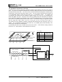
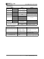
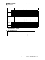
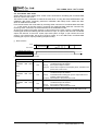
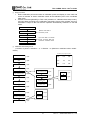
TSC-10/IC enters the Initialization mode immediately after it is turned on or reset. In this mode,
no setting is made and each mode shall be set. To transition to the available state, select the
coordinate output rate and coordinate output mode and set the operation mode.
§
Initialization mode
By either power supply ON or hardware reset/software reset, the internal initial setting is perfor
med. In the serial scheme, communication with host is available. In USB scheme, device recogn
ition process ends. In this mode, both serial and USB schemes receive a coordinate output rate
command and transition to the idle mode.
After hardware reset, it takes 500ms to transition to the initialization mode.
In using the EEPROM, EEPROM data is read in this mode.
§
Idle mode
TSC-10/IC enters this operation waiting mode after the coordinate output rate setting command is received. Transition to each mode takes place in this mode.
§
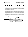
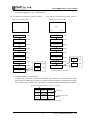
Coordinate data mode
In this mode, analog data obtained from touch screen is output as coordinate data with 10 bit resolution
without any calibration.
This mode starts in the “idle mode“ by receiving the coordinate data send start command, and returns
to “idle mode” again after receiving the coordinate data send end command. By receiving reset command, it transitions to the ”initialization mode“.
This mode is used when host driver implements the calibration function, and also when necessary data
is obtained in the calibration data setup mode.
§
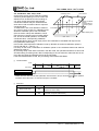
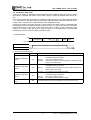
Calibration data setup mode
In this mode, calibration data used in “calibration data mode“ is set. Transition to this mode takes place
when the setup mode start command is received in the idle mode. Select an appropriate calibration
point among:
- X=2, Y=2 (four point calibration)
- X=3, Y=3 (nine point calibration) and
- X=2, Y=2 (four point calibration) plus one center position (five point calibration)
When this mode ends, calibration data is entered to EEPROM.
§
Calibration data read mode
In this mode, setup data is read out from EEPROM if in using EEPROM, data set in the ”calibration
data setup mode“ is stored to EEPROM. It is used if setting data is to be confirmed. Transition to this
mode takes place and calibration data is output to the host if in the idle mode, calibration data read
command is received.
§
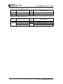
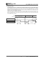
Calibration data mode
In this mode, individual difference and loss in the touch screen are corrected and coordinate value
output is performed. Using calibration data set in the ”calibration data setup mode“, touch screen input
point and indicator’s cursor display position can be matched.
In using this mode, the host driver needs no calibration function.
Using “calibration data setup mode“ setting value to set the coordinate data maximum value, maximum
value can be limited to 10bits or less.
This mode starts when in the idle mode, any ”calibration data send start command“ is received, and
returns to the idle mode when receiving the calibration data send end command. When receiving the
reset command, this mode transitions to the initialization mode.
6
Rev.1.4 ©2004-2005 DMC Co., Ltd.