Download O S F O S F Brief Operating Instructions for PD 60 /61
Transcript
Stand: 01.12.2005
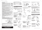
Operation without display
Connecting the device
10.5…45 V DC
10.5…30 V DC (Ex)
4…20 mA
Operating keys in the
electronics compartment
Test signal
SOF
Test
Brief Operating Instructions
for PD 60 /61 and PM50/51 SW 2.0
Damping [t]
Only for skilled personnel who have read
the relevant Operating Instructions (9499…):
PD 60/61 : 9499-040-79711
PM 50/51 : 9499-040-79811
LED
+
–
Test
4... 20mA
1
Test
2
Display
on Sensor
off
+
E
O or S
Navigation in the picklist or
editing the characters
O and S Esc. (cancel),
Previous menu item
Confirm entry
F
Next menu item
O+S+F Reset all parameters
(Code 7864)
–5–
Press O-key
for 3 seconds
Does the LED
light up?
yes*
Does the LED
light up?
yes*
Does the LED
light up?
yes*
Release key
Release key
Release key
* If no, see Operating Instructions
–4–
Operation with display
Display options
Operation with display
Symbols
Operation with display
Setting options (examples)
Function name Value
Header line
Main line
Information
line
Symbols
ID no.
Lock (locking via
hardware or software)
Communication active
Selection
options
Value that
can be edited
Unit
Square-root measurement
Bargraph
Unit
Measured value tendency increasing
Measured value tendency decreasing
Measured value tendency constant
–7–
Quick setup menu
Pressure
Press F to access
GROUP SELECTION
First page 9, then
correct orientation
of the device (zero)1)
Enter 4 mA value
without reference
pressure
Enter 20 mA value
without reference
pressure
Enter damping
time
Select language
Select measuring mode
Select quick setup
menu
1) POS. INPUT VALUE or POS. ZERO ADJ.
–9–
Press S-key
for 3 seconds
–3–
–6–
Quick setup menu
Pressure – Level – Flow
Press F-key
for 3 seconds
–2–
Alarm present
–
Position ca libration Lower-range value Upper-range value
Pressure at
Desired pressure Desired pressure
the device
is present
is present
Acting pressure Acting pressure
Acting pressure
accepted for
accepted for
accepted for
position calibration lower range value upper range value
Position of the jumper
for 4…20 mA test signal
11.5…45 V DC
11.5…30 V DC (Ex)
Operation with display
External push buttons
Operation without display
Measuring mode pressure
– 10 –
Current
measured value
confirm = edit or accept menu item
abort = next menu item
–8–
Quick setup menu
Level
Quick setup menu
Flow
First page 9, then
correct orientation
of the device (zero)1)
Enter maximum flow
of primary device
First page 9, then
correct orientation
of the device (zero)1)
Enter level value for
lower calibration
point2)
Enter level value for
upper calibration
point2)
Enter damping
time
Enter maximum
pressure of primary
device
Enter damping
time
2) Display for LEVEL MODE "linear" and
CALIBRATION MODE "wet" only.
– 11 –
– 12 –
9499-047-12411 (11.05)
on
off
1
Device identification
LED
Damping [t]
Damping [t]
Damping and locking
1
2
2
Display
on Sensor
71024573
off
PMA Prozeß- und Maschinen-Automation GmbH
Device name:
_____________________
Order code:
_____________________
TAG no.:
DIP Switch 1
DIP switch 2
Pos. off = locked Pos. off = damping off
Pos. on = unlocked Pos. on = damping on
Factory setting: off
– 13 –
Factory setting: on (2 sec.)
_____________________
__________________________________
__________________________________
71024573
– 14 –
– 15 –
PMA Prozeß- und MaschinenAutomation GmbH
Miramstraße 87
D - 34123 Kassel
Germany
Tel.: +49 561 505 1307
Fax: +49 561 505 1710
E-Mail: [email protected]
Internet: http://www.pma-online.de
9499-047-12411 (11.05)
– 16 –
9499-047-12441 (03.06)


