1
USER'S GUIDE
Date
: 28 August 2006
Doc. no. :DSP_master_BSP_UG
Iss./Rev : 1.0
Page
:1
User's Guide
DSP Master BSP
(using the UC1394a-3 MCM)
Orsys Orth System GmbH, Am Stadtgraben 25, 88677 Markdorf, Germany
http://www.orsys.de
USER'S GUIDE
DSP MASTER BSP
Date
: 28 August 2006
Doc. no. :DSP_master_BSP_UG
Iss./Rev : 1.0
Page
:2
Contents
1 PREFACE...................................................................................................................... 5
1.1
Document Organization ......................................................................................................... 5
1.2
Documentation Overview ...................................................................................................... 5
1.3
Notational Conventions ......................................................................................................... 5
1.4
Trademarks ............................................................................................................................. 7
1.5
Revision History ..................................................................................................................... 7
2 SYSTEM OVERVIEW .................................................................................................... 8
2.1
Block Diagram ........................................................................................................................ 9
2.2
Peripheral Interface................................................................................................................ 9
2.3
Streaming Interface................................................................................................................ 9
3 BSP FEATURES DESCRIPTION ................................................................................ 11
3.1
FPGA Address Map.............................................................................................................. 11
3.2
Version Register (VER) ........................................................................................................ 11
3.3
System Control Functions (SYS_CTL) ............................................................................... 13
3.4 Peripheral interface.............................................................................................................. 14
3.4.1 Peripheral Interface Registers ............................................................................................. 15
3.4.2 Using the Peripheral Interface ............................................................................................. 17
3.4.3 Peripheral Interface Write Accesses ................................................................................... 17
3.4.4 Peripheral Interface Read Accesses ................................................................................... 21
3.4.5 Peripheral Interface Usage Notes ....................................................................................... 25
3.5 Software Streaming.............................................................................................................. 27
3.5.1 Software Streaming Registers............................................................................................. 27
3.5.2 Software Streaming Programming ...................................................................................... 34
4 INDIVIDUAL SIGNAL DESCRIPTION......................................................................... 36
4.1
Peripheral Interface.............................................................................................................. 37
4.2
Reset...................................................................................................................................... 37
5 INTERFACE CHARACTERISTICS ............................................................................. 39
5.1
Reset Input............................................................................................................................ 39
USER'S GUIDE
DSP MASTER BSP
Date
: 28 August 2006
Doc. no. :DSP_master_BSP_UG
Iss./Rev : 1.0
Page
:3
5.2 Peripheral Interface.............................................................................................................. 39
5.2.1 Peripheral Interface Electrical Characteristics..................................................................... 39
5.2.2 Peripheral Interface Signal Timing ...................................................................................... 39
5.3
Software Streaming Performance....................................................................................... 40
6 DEVELOPMENT SUPPORT ....................................................................................... 42
6.1
Software Development......................................................................................................... 42
6.2
FPGA Development.............................................................................................................. 42
7 LIST OF ABBREVIATIONS USED IN THIS DOCUMENT .......................................... 43
8 LITERATURE REFERENCES..................................................................................... 44
USER'S GUIDE
DSP MASTER BSP
Date
: 28 August 2006
Doc. no. :DSP_master_BSP_UG
Iss./Rev : 1.0
Page
:4
List of Tables
Table 1: FPGA register map............................................................................................................ 11
Table 2: Peripheral interface settings.............................................................................................. 15
Table 3: Pinout sorted by pins......................................................................................................... 36
Table 4: /RESET_IN signal levels and maximum loads .................................................................. 39
Table 5: /RESET_IN timing parameters .......................................................................................... 39
Table 6: Peripheral interface signal levels and maximum loads ..................................................... 39
Table 7: Peripheral interface read timing parameters ..................................................................... 40
Table 8: Peripheral interface read timing parameters ..................................................................... 40
Table 9: Software streaming performance parameters ................................................................... 41
List of Figures
Figure 1: Internal block diagram of the UC1394a-3 with DSP Master BSP ...................................... 9
Figure 2: peripheral interface block diagram ................................................................................... 14
Figure 3: Software streaming block diagram................................................................................... 27
Figure 4: Peripheral interface read timing diagram ......................................................................... 40
Figure 5: Peripheral interface write timing diagram......................................................................... 40
USER'S GUIDE
DSP MASTER BSP
Date
: 28 August 2006
Doc. no. :DSP_master_BSP_UG
Iss./Rev : 1.0
Page
:5
1 Preface
This document describes the DSP Master Board Support Package (BSP). This BSP adds an
asynchronous 16-bit peripheral interface and a software streaming interface to the UC1394a-3
MCM. The document includes FPGA register description and FPGA register programming
documentation for these interfaces.
1.1
Document Organization
This document is organized as follows:
• Chapter 2 gives a brief overview of the whole system and its interfaces
• Chapter 3 describes each interface in detail, including the associated registers
• Chapter 4 gives an overview of all signals and describes the signals added by the DSP
master BSP in detail.
• Chapter 5 lists DC and and switching chracteristics
• Chapter 6 describes what is required for software development with this BSP
• Chapter 7 explains the abbreviations that are used throughout this document
• Chapter 8 lists documents that contain further information
1.2
Documentation Overview
This chapter lists the documentation from Orsys that is shipped together with the DSP master
board support package. Further documents from other vendors are listed in chapter 8 and are
referenced throughout the document in square brackets.
UC1394a-3 Hardware Reference Guide [17] (UC1394a-3_hrg.pdf):
Describes the hardware of the UC1394a-3 MCM. It is intended to get an overview of the multi chip
module and the features provided by it.
DSP Development Kit User's Guide [18] (DSP_DevKit_UG.pdf):
Describes software development for the UC1394a-3 MCM using the module support library from
Orsys. The module support library is a collection of declarations and low level drivers that allow to
access hardware on the board, such as loading the FPGA, using the UART as debug interface etc.
This document also contains a detailed explanation of the IEEE1394 interface. Furthermore it
describes the environment that the carrier board adds to the UC1394a-3 MCM along with some
quick start examples.
IEEE1394 embedded API User's Guide [19] (emb_1394_API_UG.pdf):
Describes the application programmer interface (API) for the IEEE1394 subsystem.
1.3
Notational Conventions
Names of registers, bit fields and single bits are written in capital letters.
Example: LLC_VERSION
Names of signals are also given in capital letters, active low signals are marked with a '/' at the
beginning of the name.
Example: /RESET_IN
Configuration parameters, function names, path names and file names are written in italic typeface.
Example: dev_id
Source code examples are given in a small, fixed-width typeface.
Example: int a = 10;
Date
: 28 August 2006
Doc. no. :DSP_master_BSP_UG
Iss./Rev : 1.0
Page
:6
USER'S GUIDE
DSP MASTER BSP
Menus and commands from menus and submenus are enclosed in double-quotes. Example:
Create a new project using the "Create Project..." command from the "File" menu.
The members of a bit field or a group of signals are numbered starting at zero, which is the least
significant bit.
Example: CFG[4:0] identifies a group of five signals, where CFG0 is the least significant bit and
CFG4 is the most significant bit.
If necessary, numbers are represented with a suffix that specifies their base.
Example: 12AB16 is a hexadecimal number (base 16 = hexadecimal) and is equal to 477910.
The bit fields of a register are displayed with the most significant bit to the left. Below each bit field
is a description of its read / write accessibility and its default value:
15
14
13
12
11
10
6
5
4
3
2
1
0
A
B
C
D
E
F
G
H
I
J
K
L
N
O
r,w,0
r,w,0
r,w,0
r,w,0
r,w,0
r,w,0
r,w,0102
r,0
r,wc,0
w
r,w,0
rc,0
r,w,0
r,w,0
accessibility and default value
9
8
7
legend:
r
bit is readable
rc
this bit is cleared after a read
r,w bit is readable and writeable, reading yields the previously written value unless otherwise
specified.
w
bit is writeable, read value is undefined
wc writing a '1' to this bit clears it
w,0 bit is write-only, reading always yields 0.
0
default value
USER'S GUIDE
DSP MASTER BSP
1.4
Date
: 28 August 2006
Doc. no. :DSP_master_BSP_UG
Iss./Rev : 1.0
Page
:7
Trademarks
TI, Code Composer, DSP/BIOS and TMS320C5000 are registered trademarks
of Texas Instruments.
Microsoft® and Windows® are either registered trademarks or
trademarks of Microsoft Corporation in the United States and/or other
countries.
Hypterterminal is a trademark of Hilgraeve Inc.
All other brand or product names are trademarks or registered trademarks of
their respective companies or organizations.
1.5
Revision History
Revision
1.0
Changes
First release
USER'S GUIDE
DSP MASTER BSP
Date
: 28 August 2006
Doc. no. :DSP_master_BSP_UG
Iss./Rev : 1.0
Page
:8
2 System Overview
The DSP Master BSP adds the following interfaces and features:
• 16-bit asynchronous peripheral interface
• streaming interface
• system reset initiated by DSP watchdog timer
• system reset initiated by software
This creates a versatile development platform featuring low-cost and small size, ready to be used
in high volume production lots.
For easy start of development, the UC1394a-3 with DSP Master BSP is available in combination
with the DSP Development Kit. Please contact Orsys for further information on this development
kit.
USER'S GUIDE
DSP MASTER BSP
2.1
Date
: 28 August 2006
Doc. no. :DSP_master_BSP_UG
Iss./Rev : 1.0
Page
:9
Block Diagram
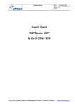
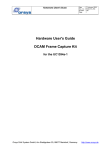
The block diagram below gives an overview of the FPGA connections on a UC1394a-3 MCM.
Figure 1: Internal block diagram of the UC1394a-3 with DSP Master BSP
2.2
Peripheral Interface
The peripheral interface provides a 16-bit asynchronous interface with programmable timings for
glueless connection to a peripheral component, such as a memory, FIFO, etc. A detailed
description of the peripheral interface can be found in chapter 3.3.
2.3
Streaming Interface
The UC1394a-3 MCM has two 400Mbps IEEE1394 ports. The IEEE1394 API allows to set up the
chipset for high-speed software streaming. Software streaming is done over a register interface
USER'S GUIDE
DSP MASTER BSP
Date
: 28 August 2006
Doc. no. :DSP_master_BSP_UG
Iss./Rev : 1.0
Page
: 10
which is implemented in the FPGA. Software streaming allows transparent, low level data transfer
with minimum software overhead. Software streaming is described in chapter 3.5.
The streaming interface is a part of the IEEE1394 interface and uses isochronous streaming. For a
detailed description of the IEEE1394 interface and isochronous streaming please refer to [18].
Date
: 28 August 2006
Doc. no. :DSP_master_BSP_UG
Iss./Rev : 1.0
Page
: 11
USER'S GUIDE
DSP MASTER BSP
3 BSP Features Description
This section describes the features provided by the DSP Master BSP in detail. The hardware and
common features of the UC1394a-3 MCM are described in the Hardware Reference Guide [17].
On-chip interfaces of the DSP are described by the respective documents from TI, that are listed in
chapter 8.
3.1
FPGA Address Map
The registers listed in Table 1 are implemented in the FPGA by the DSP Master BSP. All of these
registers are 32 bit wide and should typically accessed as 32 bit by application software. The
register VERSION contains the version and revision of the FPGA design. A part of the register
SYS_CTL is used for system control functions which are described in 3.3. The peripheral interface.
is accessed over the remaining bits in SYS_CTL and over PER_DATA as described in chapter 3.4.
The registers prefixed with STR_ are used for software streaming and are described in chapter 3.5.
Register address
00800016
00800216
00800416
00800616
00800816
00800A16
00800C16
00800E16
Register name
VERSION
SYS_CTL
PER_DATA
STR_DATA
STR_CTRL
STR_HDR
STR_LVL
STR_INT
Description
FPGA version register (read-only)
System control register
Peripheral data register
Streaming data register
Streaming control register
Streaming header register
Streaming level register
Streaming interrupt mask/flag register
Table 1: FPGA register map
3.2
Version Register (VER)
This register contains information about the FPGA version and revision. It can be used by
application software to check that the correct FPGA version is loaded.
Address:
00800016
Encoding:
31
16 15
RESERVED
r,0000000000000000
8 7
VER
r
0
REV
r
FPGA revision (REV)
This bit field contains the current FPGA revision. The FPGA revision can be changed due to bug
fixes or product enhancement.
FPGA version (VER)
This bit field identifies the current FPGA version. The version defines the functional behavior of the
FPGA as well as the supported registers. For the DSP master BSP, version 2 must be used. The
following FPGA versions are currently available for the UC1394a-3.
USER'S GUIDE
DSP MASTER BSP
FPGA version
0116
0216
applicable for
Streaming BSP
Bus master BSP
Date
: 28 August 2006
Doc. no. :DSP_master_BSP_UG
Iss./Rev : 1.0
Page
: 12
Date
: 28 August 2006
Doc. no. :DSP_master_BSP_UG
Iss./Rev : 1.0
Page
: 13
USER'S GUIDE
DSP MASTER BSP
Application software should check the version register after loading the FPGA.
Programming example:
#include "dsp_master_bsp.h" /* board support package + basic hardware def's */
#include "fpgaload.h"
/* FPGA loader */
// load FPGA from Flash
if (FpgaLoad (UC1394A3_FLASH_FPGA_CODE, UC1394A3_FLASH_FPGA_LENGTH) != FPGA_SUCCESS)
{
UC1394A3_LED_ON
while (1); // stop
}
// check for correct FPGA version
usFpgaVersion = (UC1394A3_VER & UC1394A3_VER_VERSION_MASK) >> 8;
if (usFpgaVersion != UC1394A3_MASTER_BSP_VER)
{
UC1394A3_LED_ON
while(1); //stop
}
3.3
System Control Functions (SYS_CTL)
Three bits in the system control register are used for system control purposes and are described
below. The remaining bits are used for operation of the peripheral interface and are described in
chapter 3.4.1.1.
Address:
00800216
Encoding:
31
26 25
BRSTSZ
r,w,000001
15
12
11
HOLD
RFETCH
r,w,0001
w,0
10
WRIE
r,w,0
22 21
SETUP
r,w,0001
9
RRIE
r,w,0
8
UN
r,0
7
6
OV WBREQ
r,0
r,1
5
4
3
WDONE RBREQ RREQ
r,1
r,0
r,0
16
STROBE
r,w,000001
2
DCM
r,w,0
1
SWR
w,0
0
WDE
r,w,0
Watchdog enable (WDE)
If the WDE is set to 1, resets over the DSP watchdog timer are enabled. A system reset will be
generated, whenever the DSP watchdog timer times out. This bit is set to 0 after loading the FPGA
and can only be set but not be cleared by application software. Thus, if the watchdog line is
enabled, there is no way to disable it. To implement watchdog functionality the WDTOUT output
and the watchdog timer of the DSP must be programmed accordingly. For a description of the DSP
watchdog timer please refer to [7].
Software reset (SWR)
This bit can be used by application software to trigger a system reset. Setting this bit to 1 triggers
the on-board reset generator, which generates a hardware reset pulse that resets all components
of the UC1394a-3. The SWR bit is always returns 0.
DCM status (DCM)
This bit can be used to check if the internal FPGA clocks are stable. DCM should always be
checked after loading code to the FPGA. This is described in the code fragment below.
USER'S GUIDE
DSP MASTER BSP
//
//
//
if
Date
: 28 August 2006
Doc. no. :DSP_master_BSP_UG
Iss./Rev : 1.0
Page
: 14
load FPGA-image from Flash
size of data stream is retrieved from FPGA code header in flash
FPGA code header is skipped (may also be included)
(FpgaLoad (UC1394A3_FLASH_FPGA_CODE,
UC1394A3_FLASH_FPGA_LENGTH) != FPGA_OK)
{
UC1394A3_LED_ON;
while (1) ; // stop
}
// wait until internal FPGA clocks are stable
while ((UC1394A3_SYS_CTL & UC1394A3_SYS_CTL_DCM) == 0)
asm (" nop");
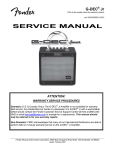
3.4
Peripheral interface
The peripheral interface implements a 16-bit bus with asynchronous control signals and
programmable timing. Interface operation is de-coupled from the DSP EMIF operation by two
FIFOs, one for each direction. This allows to access the peripheral interface with minimum CPU
overhead.
Figure 2: peripheral interface block diagram
Connected peripheral components are selected using a chip select signal (/PER_CS). Transfer
direction is indicated by PER_R/W. Data is applied to PER_D[15:0] if the access is a write access.
A common strobe signals (/PER_STRB) and two direction-specific strobe signals (/PER_RD,
/PER_WR) control sampling of read and write data.
Accesses are done in three phases with programmable duration:
• During the setup phase, /PER_CS, PER_R/W and, for write accesses, PER_D[15:0] are
active / contain valid data.
• During the strobe phase, /PER_STRB, /PER_RD (read accesses) and /PER_WR (write
accesses) are active. Read data is sampled at the end of the strobe phase with the rising
edge of /PER_STRB. Peripheral components typically sample write data with the rising
edge of /PAR_STRB or /PER_WR.
• During the access phase /PER_CS and, in case of a write access, PER_D[15:0] are kept
active.
All three access phases can be programmed to a different number of clocks as shown in Table 2.
Date
: 28 August 2006
Doc. no. :DSP_master_BSP_UG
Iss./Rev : 1.0
Page
: 15
USER'S GUIDE
DSP MASTER BSP
Access Settings
phase
Setup
Strobe
Hold
min
11
1
0
Timings
max
15
63
15
default
1
1
1
CPU:
294.912 MHz
CPU: 196.608 MHz
EMIF:
73.728 MHz
EMIF: 98.304 MHz
min
max
default
min
max
13.6 ns
203 ns 13.6 ns
10.2 ns
153 ns
13.6 ns
854 ns 13.6 ns
10.2 ns
641 ns
0 ns
203 ns 13.6 ns
0 ns
153 ns
default
10.2 ns
10.2 ns
10.2 ns
Table 2: Peripheral interface settings
3.4.1 Peripheral Interface Registers
The peripheral interface has two address locations: Operation control and status are located in the
system control register (SYS_CTL). Peripheral interface data is accessed through the peripheral
data register (PER_DATA).
3.4.1.1 System Control Register (Peripheral Interface)
Description:
Most bits of this register control peripheral interface operation. The remaining bits are used for
system-level control purposes and are described in chapter 3.3.
Address:
00800216
Encoding:
31
26 25
BRSTSZ
r,w,000001
15
12
11
HOLD
RFETCH
r,w,0001
r,w,0
10
WRIE
r,w,0
22 21
SETUP
r,w,0001
9
RRIE
r,w,0
8
UN
r,0
7
6
OV WBREQ
r,0
r,1
5
4
3
WDONE RBREQ RREQ
r,1
r,0
r,0
16
STROBE
r,w,000001
2
DCM
r,w,0
1
SWR
w,0
0
WDE
r,w,0
Single word read request (RREQ)
This bit is used for peripheral read transfers. It can be used to check that at least one word of data
is present in the read FIFO, indicated by RREQ = 1. This bit is used for single-word transfers.
Burst read request (RBREQ)
This bit is used for peripheral read transfers. It can be used to check that at least one block of data
(BRSTSZ 16-bit words) is present in the read FIFO, indicated by RBREQ = 1. This bit is used for
burst transfers. It is de-activated after BRSTSZ words have been read out of the FIFO.
External transfer done (WDONE)
This bit is used for peripheral write transfers. It can be used to check that the write FIFO is empty
and all external bus cycles are completely finished. This is the case when WDONE is 1.
Write burst request (WBREQ)
This bit is used for peripheral write transfers. It can be used to check that at least one block of data
(BRSTSZ 16-bit words) fits into the write FIFO. This is the case when WBREQ is 1. WBREQ is deactivated as soon as the first data word is written to the write FIFO (PER_DATA). WBREQ is only
activated again if BRSTSZ words have been written to PER_DATA or if BRSTSZ has been
1
A setting of 0 clocks is interpreted as if a setting of 1 was programmed.
USER'S GUIDE
DSP MASTER BSP
Date
: 28 August 2006
Doc. no. :DSP_master_BSP_UG
Iss./Rev : 1.0
Page
: 16
reprogrammed. For a BRSTSZ setting of 0 and 1, WBREQ is re-activated after each write to the
FIFO (if there is free space in the FIFO).
Write FIFO overflow (OV)
This bit is used for peripheral write transfers. It indicates an overflow condition of the write FIFO,
that is data was written to the FIFO while the FIFO was full. The overflow flag will be set each time
a write to the full FIFO is performed. The error indication can be cleared by writing a '1' to the OV
bit. Application software can poll this bit for detecting write errors.
Read FIFO underflow (UN)
This bit This bit is used for peripheral read transfers. It indicates an underflow condition of the read
FIFO, that is data was read from the FIFO while the FIFO was empty. The underflow flag will be
set each time, a read to the empty FIFO is performed. The error indication can be cleared by
writing a '1' to the UN bit. Application software can poll this bit for detecting read errors.
Read ready interrupt enable (RRIE)
This bit is used for peripheral read transfers. It is used to enable or disable the read ready interrupt.
If RRIE is set to 1, read-ready interrupts are enabled and an interrupt is triggered when the read
FIFO contains at least BRSTSZ words.
Write ready interrupt enable (WRIE)
This bit is used for peripheral read transfers. It is used to enable or disable write-ready interrupts. If
WRIE is set to 1, write-ready interrupts are enabled and interrupts are triggered when the write
FIFO can take up at least BRSTSZ words. A BRSTSZ setting of zero is treated the same as a
setting of 1. Subsequent interrupts can only be triggered after BRSTSZ words have been written to
the FIFO.
Read pre-fetch (RFETCH)
This bit is used for peripheral read transfers. This bit is used to trigger a single-word read (BRSTSZ
= 0) or a read burst (BRSTSZ > 0) on the peripheral interface. Single-word reads must always be
triggered manually using RFETCH. Also, after modifying BRSTSZ from zero to a nonzero value,
the very first read burst must be triggered using RFETCH. Only after that, read bursts are
automatically re-triggered. Reading RFETCH returns the state of the fetch operation: If RFETCH is
read as 1, read operation on the peripheral interface is either pending due to a higher priority write
operation or still in progress. If RFETCH is read as 0, read operation on the external interface has
been completed. Reading RFETCH is mainly intended for diagnostic purposes and should not be
used for handshaking. Application software should use RREQ and RBREQ instead to poll for read
data being available.
Number of hold clock cycles (HOLD)
This bit field is used for peripheral transfers in both directions. It controls the number of clock
cycles for the setup phase (0 .. 15) where chip select (/PER_CS), direction select (PER_R/W) and
write data (PER_D [15:0]) are held after the strobe signals (/PER_STRB and /PER_WR in case of
a write access and /PER_STRB and /PER_RD in case of a read access) were deactivated.
Number of strobe clock cycles (STRB)
This bit field is used for peripheral transfers in both directions. It controls the number of clock
cycles (1 .. 63) for the strobe phase of an access and therefore the width of the strobe signals
/PER_STRB, /PER_WR and /PER_RD. Setting STRB to 0 is treated as a setting of 1.
Number of setup clock cycles (SETUP)
This bit field is used for peripheral transfers in both directions. It controls the number of clock
cycles (1 .. 15) for the setup phase where /PER_CS, PER_R/W and, for write accesses,
PER_D[15:0] are activated before the strobe signals (/PER_STRB and /PER_WR for write
USER'S GUIDE
DSP MASTER BSP
Date
: 28 August 2006
Doc. no. :DSP_master_BSP_UG
Iss./Rev : 1.0
Page
: 17
accesses and /PER_STRB and /PER_RD for read accesses) go active. Setting SETUP to 0 is
treated as a setting of 1.
Number of 16-bit words per burst transfer (BRSTSZ)
This bit field is used for peripheral transfers in both directions, but with a slightly different meaning.
Write bursts:
BRSTSZ specifies the amount of data that can be written into the write FIFO in one block. If the
write FIFO has enough space for BRSTSZ words, a write-burst request is signaled via the WBREQ
bit and, if enabled by WRIE, also over an interrupt. The write-burst request is deactivated after the
first write to PER_DATA and goes active again only after BRSTSZ words have been written to
PER_DATA and the write FIFO has enough space for the next BRSTSZ words, or if BRSTSZ has
been reprogrammed. A BRSTSZ setting of 0 is treated as a BRSTSZ setting of 1 and causes a
write-burst request after each single word.
Read bursts:
BRSTSZ specifies the burst size of a read burst on the peripheral interface as well as the amount
of data that can be read from the read FIFO in one block. If a read burst was triggered (either
manually by RFETCH or automatically), a read-burst request is signaled by RBREQ and, if
enabled by RRIE, also an interrupt. The read-burst request is de-activated after BRSTSZ words
have been read out of the FIFO. A new read burst is triggered automatically if BRSTSZ is nonzero
and the read FIFO has at least BRSTSZ words free space. If BRSTSZ is set to 0, no read-burst
request is generated, but single-word handshaking over RREQ can be used instead.
3.4.1.2 Peripheral Data Register
Description:
This register is used to transfer data between the DSP and the read and write FIFOs of the
peripheral interface. These FIFOs are implemented in the FPGA. Application software can
implement software controlled transfers or DMA transfers. Transfers can be triggered without
handshake, with polling or interrupt driven. The EMIF of the DSP supports only 32-bit read
accesses. Even if the software does a 16-bit read from the peripheral interface, 32 bits are actually
read by the EMIF. Therefore it is recommended to read data from PER_DATA only by 32-bit read
accesses. Data can be written to PER_DATA by 16-bit or 32-bit accesses. 32-bit write accesses
are faster than two consecutive 16-bit accesses, because they consume less bus time on the EMIF
(one 4-byte access instead of two 2-byte accesses) as well as on the peripheral interface (the 4byte EMIF access provides that data in time, so that even with the fastest timing, the two accesses
can take place within one chip select cycle (2 /PER_STRB pulses without /PER_CS going
inactive). Therefore it is recommended to write data to PER_DATA only by 32-bit write accesses.
Suitable declarations of PER_DATA exist in the module support library's header files.
Address:
00800616
Encoding:
31
0
PER_DATA
r, w
3.4.2
Using the Peripheral Interface
3.4.3 Peripheral Interface Write Accesses
Write accesses to the peripheral interface are buffered by a FIFO in order to keep peripheral timing
independent of the EMIF timing (which is configured as 8-bit synchronous memory type). For each
16-bit word written to PER_DATA, a bus cycle on the peripheral interface is generated. Data can
be written as 16-bit accesses or as 32-bit accesses with MSW first. If application software can
USER'S GUIDE
DSP MASTER BSP
Date
: 28 August 2006
Doc. no. :DSP_master_BSP_UG
Iss./Rev : 1.0
Page
: 18
ensure that the external bus cycles can finish before new data is written to the FIFO, no handshake
is necessary and data can simply be written to PER_DATA as shown below. This method can be
used if
• peripheral accesses occur with sufficiently low data rate
• peripheral accesses are programmed to have not more than 4 clocks in total (setup +
strobe + hold ≤ 4) are done with a large distance:
#include "dsp_master_bsp.h" /* board support package + basic hardware def's */
...
// set up transfer timings
UC1394A3_SYS_CTL = (1L << UC1394A3_SYS_CTL_SETUP_SHIFT) |
(1L << UC1394A3_SYS_CTL_STROBE_SHIFT) |
(0L << UC1394A3_SYS_CTL_HOLD_SHIFT));
//main loop
while(1)
{
//write some 16- or 32-bit values to the peripheral interface
UC1394A3_PER_DATA16 = 0x0001;
UC1394A3_PER_DATA32 = 0x02030405;
}
However, usually the application software must check for the peripheral interface to be ready. This
check can be done on a single-word basis or block-based. Single-word handshake is more simple
and is suitable for low bandwidth requirements. Block-based handshake is intended for fast
transfers with low CPU overhead. Both methods use the same handshaking mechanisms.
3.4.3.1 Peripheral Interface Write Accesses Using Single-word Handshake
Application software can simply poll the WBREQ bit for free space in the write FIFO before writing
data to it:
#include "dsp_master_bsp.h" /* board support package + basic hardware def's */
...
// set up transfer timings
UC1394A3_SYS_CTL = (1L << UC1394A3_SYS_CTL_SETUP_SHIFT) |
(4L << UC1394A3_SYS_CTL_STROBE_SHIFT) |
(1L << UC1394A3_SYS_CTL_HOLD_SHIFT)
|
(0L << UC1394A3_SYS_CTL_BURSTSZ_SHIFT));
//main loop
while(1)
{
//wait for free space in the write FIFO
while((UC1394A3_SYS_CTL & UC1394A3_SYS_CTL_WBREQ) == 0);
//write one 16-bit value to the peripheral interface
UC1394A3_PER_DATA16 = 0x0001;
//wait for free space in the write FIFO
while((UC1394A3_SYS_CTL & UC1394A3_SYS_CTL_WBREQ) == 0);
//write next 16-bit value to the peripheral interface
UC1394A3_PER_DATA16 = 0x0002;
}
To remove the CPU overhead for polling WBREQ, interrupts can be used.
#include "dsp_master_bsp.h" /* board support package + basic hardware def's */
#include "msl.h"
/* module support library */
void interrupt PeriphWriteIsr(void);
void main (void)
{
INT16U usFpgaVersion;
/* sets up interrupts, clears and enables the cache */
InitDsp (eSameSpeed);
/* install interrupt handler for peripheral accesses */
IntHook (UC1394A3_INT_FPGA1, PeriphWriteIsr);
/* load FPGA-image from flash memory */
if (FpgaLoad (UC1394A3_FLASH_FPGA_CODE,
// wait until internal FPGA clocks are stable
while ((UC1394A3_SYS_CTL & UC1394A3_SYS_CTL_DCM) == 0);
/* clear FPGA interrupts and enable them */
IntClear(UC1394A3_INT_FPGA1);
IntEnable(UC1394A3_INT_FPGA1);
/* initial set up of peripheral interface to 4-10-4 timing */
UC1394A3_SYS_CTL = (( 4L << UC1394A3_SYS_CTL_SETUP_SHIFT)
|
USER'S GUIDE
DSP MASTER BSP
Date
: 28 August 2006
Doc. no. :DSP_master_BSP_UG
Iss./Rev : 1.0
Page
: 19
(10L << UC1394A3_SYS_CTL_STROBE_SHIFT) |
( 4L << UC1394A3_SYS_CTL_HOLD_SHIFT)
|
( 0L << UC1394A3_SYS_CTL_BURSTSZ_SHIFT));
/* enable write interrupts in the FPGA. This triggers the transfers */
UC1394A3_SYS_CTL = UC1394A3_SYS_CTL | UC1394A3_SYS_CTL_WRIE;
/* empty main loop */
while(1);
}
void interrupt PeriphWriteIsr(void)
{
/* check if this is really our interrupt */
if (UC1394A3_SYS_CTL & UC1394A3_SYS_CTL_WBREQ)
{
/* indicate access. */
/* The XF output can be used to trigger an oscilloscope */
asm(" BSET XF");
{volatile int i = 5; while(--i);}
asm(" BCLR XF");
/* write data to the peripheral interface */
UC1394A3_PER_DATA16 = 0x55AA;
}
/* check for FIFO overflows (may never happen! */
if (UC1394A3_SYS_CTL & UC1394A3_SYS_CTL_OV)
UC1394A3_LED_ON;
}
3.4.3.2 Peripheral Interface Write Accesses Using Burst Handshake
When using burst handshake, burst size must be set up before operation. All further operation is
the same as for single-word handshake, WBREQ and interrupts now act on a burst instead of a
single word.
#include "dsp_master_bsp.h" /* board support package + basic hardware def's */
...
// set up transfer timings and burst size
UC1394A3_SYS_CTL = (1L << UC1394A3_SYS_CTL_SETUP_SHIFT) |
(4L << UC1394A3_SYS_CTL_STROBE_SHIFT) |
(1L << UC1394A3_SYS_CTL_HOLD_SHIFT)
|
(5L << UC1394A3_SYS_CTL_BURSTSZ_SHIFT));
//main loop
while(1)
{
//wait for free space in the write FIFO
while((UC1394A3_SYS_CTL & UC1394A3_SYS_CTL_WBREQ) == 0);
//write 5 16-bit values to the peripheral interface
UC1394A3_PER_DATA32 = 0x00010203;
UC1394A3_PER_DATA32 = 0x04050607;
UC1394A3_PER_DATA16 = 0x0809;
}
Burst transfers can also be implemented by using DMA, so that the DSP can continue while data is
being transferred by the DMA controller. This also implements highest performance transfers,
where up to 8 16-bit words are transferred to the peripheral interface consecutively. Please note
that triggering DMA transfers directly by the peripheral interface is not possible, because only DSPinternal peripherals can trigger DMA events. Please note that some special rules apply when using
DMA transfers. See chapter 3.4.5 for details. The code example below uses the burst-ready
interrupt to trigger a DMA transfer of 16 16-bit words (transferred in 2 bursts of 8 words each). The
fact that the write FIFO is refilled before the previous burst is completely written to the peripheral
interface causes peripheral interface operation to be continuous, with /PER_CS and PER_R/W
being permanently low.
USER'S GUIDE
DSP MASTER BSP
Date
: 28 August 2006
Doc. no. :DSP_master_BSP_UG
Iss./Rev : 1.0
Page
: 20
#include "dsp_master_bsp.h" /* board support package + basic hardware def's */
#include "msl.h"
/* module support library */
/******* global variables ****************************************************/
INT32U aulTestData[8] = {0x00010203, 0x04050607, 0x08090A0B, 0x0C0D0E0F,
0x10111213, 0x14151617, 0x18191A1B, 0x1C1D1E1F};
/******* local function prototypes *******************************************/
void interrupt PeriphWriteIsr(void);
/******* function definitions ************************************************/
void main (void)
{
INT32U ulAddr;
/* sets up interrupts, clears and enables the cache */
InitDsp (eSameSpeed);
/* install interrupt handler for peripheral accesses */
IntHook (UC1394A3_INT_FPGA1, PeriphWriteIsr);
/* load FPGA-image from flash memory */
if (FpgaLoad (UC1394A3_FLASH_FPGA_CODE,
UC1394A3_FLASH_FPGA_LENGTH) != FPGA_OK)
{UC1394A3_LED_ON, while (1) ;} // stop
/* wait until internal FPGA clocks are stable */
while ((UC1394A3_SYS_CTL & UC1394A3_SYS_CTL_DCM) == 0);
/* clear FPGA interrupts and enable them */
IntClear(UC1394A3_INT_FPGA1);
IntEnable(UC1394A3_INT_FPGA1);
/* set up DMA controller */
C5501_DMA_GCR
= 0; /* keep at default */
C5501_DMA_GTCR
= 0; /* no timeouts enabled */
/* Set up DMA for transferring from aulTestData to PER_DATA */
/* Address update is done in double-indexed mode. Update sequence
*/
/* is: +1,+1,+1,+1,+1,+1,+1,+1,+1,+1,+1,+1,+1,+1,+1,+17,+1,...
*/
/* so that each burst starts on the correct (mirrored) address
*/
C5501_DMA_CCR0 = (C5501_DMA_CCR_DSTAMODE_D_INDEX
|
C5501_DMA_CCR_SRCAMODE_INCR
|
C5501_DMA_CCR_ENDPROG_IN_PROGRESS|
C5501_DMA_CCR_WP_DIS
|
C5501_DMA_CCR_REPEAT_ENDPROG
|
C5501_DMA_CCR_AUTOINIT_EN
|
C5501_DMA_CCR_EN_STOP
|
C5501_DMA_CCR_PRIO_HIGH
|
C5501_DMA_CCR_FS_ELEMENT
|
C5501_DMA_CCR_SYNC_UNSYNCED);
C5501_DMA_CSDP0 =(C5501_DMA_CSDP_DSTBEN_BURST
|
C5501_DMA_CSDP_DSTPACK_EN
|
C5501_DMA_CSDP_DST_EMIF
|
C5501_DMA_CSDP_SRCBEN_BURST
|
C5501_DMA_CSDP_SRCPACK_EN
|
C5501_DMA_CSDP_SRC_EMIF
|
C5501_DMA_CSDP_DATATYPE_32_BIT);
C5501_DMA_CICR0 = 0;
ulAddr = (INT32U)aulTestData * 2;
C5501_DMA_CSSAL0 = ((ulAddr >> 0) & 0xFFFF);
C5501_DMA_CSSAU0 = ((ulAddr >> 16) & 0xFFFF);
ulAddr = (INT32U)&UC1394A3_PER_DATA32_DMA * 2;
C5501_DMA_CDSAL0 = ((ulAddr >> 0) & 0xFFFF);
C5501_DMA_CDSAU0 = ((ulAddr >> 16) & 0xFFFF);
C5501_DMA_CEN0
= 4; /* must stay at 4x32bit = 1 DMA burst! */
C5501_DMA_CFN0
= 2; /* 2x4x32bit = 16 words */
C5501_DMA_CDEI0 = 1; /* element index must be 1 for burst operation */
C5501_DMA_CDFI0 = 17; /* frame index advances to next mirrored location */
/* Set up peripheral interface to 1-2-1 timing and */
/* burst size of 16 (16-bit words). */
UC1394A3_SYS_CTL = ((16L << UC1394A3_SYS_CTL_BURSTSZ_SHIFT) |
( 1L << UC1394A3_SYS_CTL_SETUP_SHIFT)
|
( 2L << UC1394A3_SYS_CTL_STROBE_SHIFT) |
( 1L << UC1394A3_SYS_CTL_HOLD_SHIFT));
/* Enable write interrupts in the FPGA. */
/* This triggers the transfers. */
UC1394A3_SYS_CTL = UC1394A3_SYS_CTL | UC1394A3_SYS_CTL_WRIE;
/* empty main loop */
while(1);
}
USER'S GUIDE
DSP MASTER BSP
Date
: 28 August 2006
Doc. no. :DSP_master_BSP_UG
Iss./Rev : 1.0
Page
: 21
void interrupt PeriphWriteIsr(void)
{
INT32U ulPeriphStat;
/* Get current status. Reading from the FPGA at this time doesn't */
/* interfere with DMA operation, because previous operation */
/* must have been finished before a new interrupt can be triggered. */
ulPeriphStat = UC1394A3_SYS_CTL;
/* check if this is really our interrupt */
if (ulPeriphStat & UC1394A3_SYS_CTL_WBREQ)
{
/* Trigger DMA write to the peripheral interface */
C5501_DMA_CCR0|= (C5501_DMA_CCR_EN_START | C5501_DMA_CCR_ENDPROG_DONE);
/* Check for writes to a full FIFO. FIFO overflows mustn't happen */
if (ulPeriphStat & UC1394A3_SYS_CTL_OV)
UC1394A3_LED_ON;
}
}
3.4.3.3 Checking for Completion of External Operation
Sometimes, application software must check that the external transfer has completed. This is done
by checking the WDONE bit in the SYS_CTL register. If this bit is set, the write FIFO is empty and
all external bus cycles are completely finished.
#include "dsp_master_bsp.h" /* board support package + basic hardware def's */
...
// set up transfer timings
UC1394A3_SYS_CTL = (1L << UC1394A3_SYS_CTL_SETUP_SHIFT) |
(4L << UC1394A3_SYS_CTL_STROBE_SHIFT) |
(1L << UC1394A3_SYS_CTL_HOLD_SHIFT)
|
(0L << UC1394A3_SYS_CTL_BURSTSZ_SHIFT));
//main loop
while(1)
{
//write one 16-bit value to the peripheral interface
UC1394A3_PER_DATA16 = 0x0001;
//wait until data was written to the peripheral interface
while((UC1394A3_SYS_CTL & UC1394A3_SYS_CTL_WDONE) == 0);
}
3.4.4 Peripheral Interface Read Accesses
Read accesses to the peripheral interface are FIFO buffered in order to keep peripheral timing
independent of the EMIF timing (which is configured as 8-bit synchronous memory type). The DSP
can read the FIFO using 16-bit or 32-bit accesses, however, the EMIF always reads 32 bit from
external memory. Therefore it is strongly recommended to always read 32 bit from PER_DATA.
In contrast to write accesses, application software must always check for the presence of data
before data is read from PER_DATA. Checking for data availability is done through the RREQ bit
for single-word transfers and through RBREQ for block-based transfers (of BURSTSZ size).
Peripheral interface read accesses can be done as single-word accesses or burst accesses.
Single-word accesses are simpler, but have less performance. For high bandwidth transfers, burst
transfers are recommended.
3.4.4.1 Peripheral Interface Read Accesses Using Single-word Handshake
Single Word accesses must always be triggered manually by setting the RFETCH bit to 1. Data is
available in the FIFO when RREQ is set to 1. Subsequent reads can only be triggered after the
preceding read has finished. Single-word reads are typically used for accesses to control / status
registers or for applications where only a few accesses at a low bandwidth are required.
USER'S GUIDE
DSP MASTER BSP
Date
: 28 August 2006
Doc. no. :DSP_master_BSP_UG
Iss./Rev : 1.0
Page
: 22
#include "dsp_master_bsp.h" /* board support package + basic hardware def's */
...
// set up transfer timings
UC1394A3_SYS_CTL = (1L << UC1394A3_SYS_CTL_SETUP_SHIFT) |
(4L << UC1394A3_SYS_CTL_STROBE_SHIFT) |
(1L << UC1394A3_SYS_CTL_HOLD_SHIFT)
|
(0L << UC1394A3_SYS_CTL_BURSTSZ_SHIFT));
//main loop
while(1)
{
//trigger read of one 16-bit word
UC1394A3_SYS_CTL = UC1394A3_SYS_CTL | UC1394A3_SYS_CTL_RFETCH;
//wait until data is available
while((UC1394A3_SYS_CTL & UC1394A3_SYS_CTL_RREQ) == 0);
//read data from the FIFO (Note: EMIF always reads 32 bits!)
tmp_data = UC1394A3_PER_DATA32;
//optional: clear FIFO underflow bit after read operation
UC1394A3_SYS_CTL = UC1394A3_SYS_CTL | UC1394A3_SYS_CTL_UN;
}
Single-word transfers could in principle be triggered by interrupts when RRIE is set to 1. In this
case the first read is triggered outside of the interrupt and then the interrupt service routine reads
the data from the FIFO and sets RFETCH again to trigger the next read. However, this mechanism
can be implemented easier by using burst transfers with a burst size of 1.
3.4.4.2 Peripheral Interface Read Accesses Using Burst Handshake
When using burst transfers, read cycles on the peripheral interface are always done as a
contiguous burst where /PER_CS stays active (low) during the entire burst. Burst accesses use an
automatic pre-fetch mechanism, that is, when the last word of the current burst gets read out of the
FIFO and there is enough space in the FIFO for a new burst, a new burst of data is automatically
read from the peripheral interface. This allows high bandwidth reads with minimum software
overhead. In order to avoid unwanted reads at startup, the very first burst must be triggered
manually through the RFETCH bit. After triggering the first transfer manually, BURSTSZ bus cycles
on the peripheral interface are generated and subsequent bursts are automatically triggered
whenever the first word of a burst is read out of the FIFO.
#include "dsp_master_bsp.h" /* board support package + basic hardware def's */
...
unsigned long tmp_data1;
unsigned short tmp_data2;
// set up transfer timings and burst size
UC1394A3_SYS_CTL = (1L << UC1394A3_SYS_CTL_SETUP_SHIFT) |
(4L << UC1394A3_SYS_CTL_STROBE_SHIFT) |
(1L << UC1394A3_SYS_CTL_HOLD_SHIFT)
|
(3L << UC1394A3_SYS_CTL_BURSTSZ_SHIFT));
//main loop
while(1)
{
//trigger read of one 16-bit word
UC1394A3_SYS_CTL = UC1394A3_SYS_CTL | UC1394A3_SYS_CTL_RFETCH;
//wait until data is available
while((UC1394A3_SYS_CTL & UC1394A3_SYS_CTL_RREQ) == 0);
//read data from the FIFO (Note: EMIF always reads 32 bits!)
tmp_data1 = UC1394A3_PER_DATA32;
tmp_data2 = (unsigned short)UC1394A3_PER_DATA32;
//optional: clear FIFO underflow bit after read operation
UC1394A3_SYS_CTL = UC1394A3_SYS_CTL | UC1394A3_SYS_CTL_UN;
}
At the end of a multi-burst transfer, automatic generation of read bursts can be disabled by setting
BURSTSZ to 0. Single-burst transfers can be implemented by setting up BURSTSZ, triggering a
transfer, waiting until RBREQ is set, setting BRSTSZ back to zero and then reading the data from
the read FIFO.
#include "dsp_master_bsp.h" /* board support package + basic hardware def's */
...
unsigned long tmp_data;
USER'S GUIDE
DSP MASTER BSP
Date
: 28 August 2006
Doc. no. :DSP_master_BSP_UG
Iss./Rev : 1.0
Page
: 23
// set up transfer timings and burst size
UC1394A3_SYS_CTL = (1L << UC1394A3_SYS_CTL_SETUP_SHIFT) |
(4L << UC1394A3_SYS_CTL_STROBE_SHIFT) |
(1L << UC1394A3_SYS_CTL_HOLD_SHIFT)
|
(2L << UC1394A3_SYS_CTL_BURSTSZ_SHIFT));
//trigger read of one burst (of 2 16-bit words)
UC1394A3_SYS_CTL = UC1394A3_SYS_CTL | UC1394A3_SYS_CTL_RFETCH;
//wait until data is available
while((UC1394A3_SYS_CTL & UC1394A3_SYS_CTL_RBREQ) == 0);
//switch off further reads
UC1394A3_SYS_CTL = UC1394A3_SYS_CTL & ~UC1394A3_SYS_CTL_BURSTSZ_MASK;
//read data from the FIFO
tmp_data = UC1394A3_PER_DATA32;
...
Interrupt-triggered transfers are enabled by setting RRIE to 1. When enabled, an interrupt is
generated for each new block of BURSTSZ words in the read FIFO. Interrupts are re-triggered only
after the previous block has been completely read out of the FIFO.
#include "dsp_master_bsp.h" /* board support package + basic hardware def's */
#include "msl.h"
/* module support library */
INT32U aulTestData[2];
void interrupt PeriphReadIsr(void);
void main (void)
{
/* sets up interrupts, clears and enables the cache */
InitDsp (eSameSpeed);
/* install interrupt handler for peripheral accesses */
IntHook (UC1394A3_INT_FPGA1, PeriphReadIsr);
/* load FPGA-image from flash memory */
if (FpgaLoad (UC1394A3_FLASH_FPGA_CODE,
UC1394A3_FLASH_FPGA_LENGTH) != FPGA_OK)
{
UC1394A3_LED_ON;
while (1) ; // stop
}
/* wait until internal FPGA clocks are stable */
while ((UC1394A3_SYS_CTL & UC1394A3_SYS_CTL_DCM) == 0);
/* clear FPGA interrupts and enable them */
IntClear(UC1394A3_INT_FPGA1);
IntEnable(UC1394A3_INT_FPGA1);
/* initial set up of peripheral interface to 1-2-1 timing and */
/* burst size of 4 */
UC1394A3_SYS_CTL = ((4L << UC1394A3_SYS_CTL_BURSTSZ_SHIFT) |
(1L << UC1394A3_SYS_CTL_SETUP_SHIFT)
|
(2L << UC1394A3_SYS_CTL_STROBE_SHIFT) |
(1L << UC1394A3_SYS_CTL_HOLD_SHIFT));
/* enable read interrupts in the FPGA. */
UC1394A3_SYS_CTL = UC1394A3_SYS_CTL | UC1394A3_SYS_CTL_RRIE;
/* trigger the very first transfer. All further transfers will be */
/* triggered automatically */
UC1394A3_SYS_CTL = UC1394A3_SYS_CTL | UC1394A3_SYS_CTL_RFETCH;
/* empty main loop */
while(1);
}
void interrupt PeriphReadIsr(void)
{
/* check if this is really our interrupt */
if (UC1394A3_SYS_CTL & UC1394A3_SYS_CTL_RBREQ)
{
/* indicate access. */
/* The XF output can be used to trigger an oscilloscope */
asm(" BSET XF");
{volatile int i = 5; while(--i);}
asm(" BCLR XF");
/* Read data from the peripheral interface */
aulTestData[0] = UC1394A3_PER_DATA32;
aulTestData[1] = UC1394A3_PER_DATA32;
}
/* check for reads from empty FIFO (may never happen for even burst lengths!) */
if (UC1394A3_SYS_CTL & UC1394A3_SYS_CTL_UN)
UC1394A3_LED_ON;
}
Block-based transfers can also be implemented by using DMA, so that the DSP can continue while
data is being transferred by the DMA controller. This also implements highest performance
USER'S GUIDE
DSP MASTER BSP
Date
: 28 August 2006
Doc. no. :DSP_master_BSP_UG
Iss./Rev : 1.0
Page
: 24
transfers, where up to 8 16-bit words are transferred from the peripheral interface consecutively.
Please note that triggering DMA transfers directly by the peripheral interface is not possible,
because only DSP-internal peripherals can trigger DMA events. . Please note that some special
rules apply when using DMA transfers. See chapter 3.4.5 for details. The code example below
uses the burst-ready interrupt to trigger a DMA transfer of 32 16-bit words (transferred in 4 bursts
of 8 words each).
#include "dsp_master_bsp.h" /* board support package + basic hardware def's */
#include "msl.h"
/* module support library */
/******* global variables ****************************************************/
INT32U aulTestData[16];
/******* local function prototypes *******************************************/
void interrupt PeriphReadIsr(void);
/******* function definitions ************************************************/
void main (void)
{
INT32U ulAddr;
/* sets up interrupts, clears and enables the cache */
InitDsp (eSameSpeed);
/* install interrupt handler for peripheral accesses */
IntHook (UC1394A3_INT_FPGA1, PeriphReadIsr);
/* load FPGA-image from flash memory */
if (FpgaLoad (UC1394A3_FLASH_FPGA_CODE,
UC1394A3_FLASH_FPGA_LENGTH) != FPGA_OK)
{UC1394A3_LED_ON, while (1) ;} // stop
/* wait until internal FPGA clocks are stable */
while ((UC1394A3_SYS_CTL & UC1394A3_SYS_CTL_DCM) == 0);
/* clear FPGA interrupts and enable them */
IntClear(UC1394A3_INT_FPGA1);
IntEnable(UC1394A3_INT_FPGA1);
/* set up DMA controller */
C5501_DMA_GCR
= 0; /* keep at default */
C5501_DMA_GTCR
= 0; /* no timeouts enabled */
/* Set up DMA for transferring from PER_DATA to aulTestData.
*/
/* Address update is done in double-indexed mode. Update sequence
*/
/* is: +1,+1,+1,+1,+1,+1,+1,+1,+1,+1,+1,+1,+1,+1,+1,+17,+1,...
*/
/* so that each burst starts on the correct (mirrored) address
*/
C5501_DMA_CCR0 = (C5501_DMA_CCR_DSTAMODE_INCR
|
C5501_DMA_CCR_SRCAMODE_D_INDEX
|
C5501_DMA_CCR_ENDPROG_IN_PROGRESS|
C5501_DMA_CCR_WP_DIS
|
C5501_DMA_CCR_REPEAT_ENDPROG
|
C5501_DMA_CCR_AUTOINIT_EN
|
C5501_DMA_CCR_EN_STOP
|
C5501_DMA_CCR_PRIO_HIGH
|
C5501_DMA_CCR_FS_ELEMENT
|
C5501_DMA_CCR_SYNC_UNSYNCED);
C5501_DMA_CSDP0 =(C5501_DMA_CSDP_DSTBEN_BURST
|
C5501_DMA_CSDP_DSTPACK_EN
|
C5501_DMA_CSDP_DST_EMIF
|
C5501_DMA_CSDP_SRCBEN_BURST
|
C5501_DMA_CSDP_SRCPACK_EN
|
C5501_DMA_CSDP_SRC_EMIF
|
C5501_DMA_CSDP_DATATYPE_32_BIT);
C5501_DMA_CICR0 = 0;
ulAddr = (INT32U)&UC1394A3_PER_DATA32_DMA * 2;
C5501_DMA_CSSAL0 = ((ulAddr >> 0) & 0xFFFF);
C5501_DMA_CSSAU0 = ((ulAddr >> 16) & 0xFFFF);
ulAddr = (INT32U)aulTestData * 2;
C5501_DMA_CDSAL0 = ((ulAddr >> 0) & 0xFFFF);
C5501_DMA_CDSAU0 = ((ulAddr >> 16) & 0xFFFF);
C5501_DMA_CEN0
= 4; /* must stay at 4x32bit = 1 DMA burst! */
C5501_DMA_CFN0
= 4; /* 4x4x32bit = 32 words */
C5501_DMA_CSEI0 = 1; /* element index must be 1 for burst operation */
C5501_DMA_CSFI0 = 17; /* frame index advances to next mirrored location */
USER'S GUIDE
DSP MASTER BSP
Date
: 28 August 2006
Doc. no. :DSP_master_BSP_UG
Iss./Rev : 1.0
Page
: 25
/* Set up peripheral interface to 1-2-1 timing and */
/* burst size of 32 (16-bit words). */
/* Note: if DMA burst mode is used, BURSTSZ must be set to a multiple */
/* of 8! */
UC1394A3_SYS_CTL = ((32L << UC1394A3_SYS_CTL_BURSTSZ_SHIFT) |
( 1L << UC1394A3_SYS_CTL_SETUP_SHIFT)
|
( 2L << UC1394A3_SYS_CTL_STROBE_SHIFT) |
( 1L << UC1394A3_SYS_CTL_HOLD_SHIFT));
/* enable read interrupts in the FPGA. */
UC1394A3_SYS_CTL = UC1394A3_SYS_CTL | UC1394A3_SYS_CTL_RRIE;
/* trigger the very first transfer. All further transfers will be */
/* triggered automatically */
UC1394A3_SYS_CTL = UC1394A3_SYS_CTL | UC1394A3_SYS_CTL_RFETCH;
/* empty main loop */
while(1);
}
void interrupt PeriphReadIsr(void)
{
INT32U ulPeriphStat;
/* Get current status. Reading from the FPGA at this time doesn't */
/* interfere with DMA operation, because previous operation */
/* must have been finished before a new interrupt can be triggered. */
ulPeriphStat = UC1394A3_SYS_CTL;
/* check if this is really our interrupt */
if (ulPeriphStat & UC1394A3_SYS_CTL_RBREQ)
{
/* Trigger DMA read from the peripheral interface */
C5501_DMA_CCR0|= (C5501_DMA_CCR_EN_START | C5501_DMA_CCR_ENDPROG_DONE);
/* Check for reads from an empty FIFO. FIFO errors mustn't happen */
/* for even burst lengths. */
if (ulPeriphStat & UC1394A3_SYS_CTL_UN)
UC1394A3_LED_ON;
}
}
3.4.5
•
•
•
•
•
•
•
•
•
•
Peripheral Interface Usage Notes
Write transfers have precedence over read transfers. Therefore, no read transfer will be
performed as long as there is data in the write FIFO. However, a read transfer can be
triggered by setting RFETCH while a write is currently active.
Read bursts are always finished, once started, even if a write transfer is pending.
Changing BURSTSZ does not affect the current read burst, but affects the WBREQ and
RBREQ flags. Therefore, before changing BURSTSZ, make sure, that no transfers are
currently active.
Reading from PER_DATA causes a FIFO underflow condition if there is only one 16-bit
word present in the read FIFO. This is due to the fact that the EMIF always reads 32 bit.
This FIFO underflow condition can safely be ignored. However, to avoid this situation, it is
recommended to use burst read transfers only with even sizes and to access PER_DATA
only with 32-bit transfers.
Reading from PER_DATA using 16-bit accesses is only allowed for single-word transfers
where only one 16-bit word is present in the read FIFO. Otherwise, each 2nd word will get
lost (because the EMIF always reads 32 bit from the EMIF).
Changing the access timings while an external transfer is active changes the timings for the
subsequent transfers.
Manually triggering a read is only possible when no read burst is currently in progress on
the external interface. Therefore, re-triggering the next read must only be done after the last
data of the previous burst is available (as indicated by RBREQ or, for single-word transfers,
indicated by RREQ).
Read cycles on the external interface are suspended when the read FIFO is full. This
allows to manually trigger a read burst even if the FIFO does not have enough space left.
When using DMA for transfers, no other accesses (with the same transfer direction as the
DMA transfer) should be made to the FPGA in order not to interfere with DMA operation.
When using DMA for transfers, use burst mode for transfer lengths that are multiples of 8
16-bit words. This gives the best performance. Se also the example code in chapters
USER'S GUIDE
DSP MASTER BSP
Date
: 28 August 2006
Doc. no. :DSP_master_BSP_UG
Iss./Rev : 1.0
Page
: 26
3.4.3.2 and 3.4.4.2. For other transfer lengths, single-mode DMA accesses with constant
address must be used. However, these accesses are not much faster than software.-driven
accesses.
USER'S GUIDE
DSP MASTER BSP
3.5
Date
: 28 August 2006
Doc. no. :DSP_master_BSP_UG
Iss./Rev : 1.0
Page
: 27
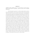
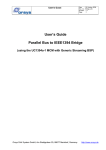
Software Streaming
Software streaming is part of the IEEE1394 interface. The IEEE1394 interface is described in detail
in [18]. Software streaming allows to transfer large amounts of data between the DSP and
IEEE1394 with minimal overhead. Data transfers are buffered by a FIFO, so that the DSP can
operate independent of the IEEE1394 timing. Streaming transfers are unidirectional and must be
set up with the IEEE1394 API as well as the streaming registers in the FPGA. The maximum
transfer rate for software streaming is listed in chapter 5.3. Software streaming uses isochronous
streaming. Isochronous streaming is explained in [18].
The DSP Master BSP allows to:
• transmit synchronization information in the data stream under software control: See
description of the SYNC bit field in the STR_HDR register
• synchronize receive operation to the incoming data stream: See description of the
RXSYNC bit field in the STR_CTL register.
• include isochronous packet headers in the received data stream for multi-stream reception
and diagnostic information: See description of the RXHDR bit field in the STR_CTL register.
Figure 3: Software streaming block diagram
3.5.1 Software Streaming Registers
Software streaming operation and the data transfer is done over a set of registers. These registers
are described in detail in this chapter together with programming examples. How to set up and use
software streaming operation is shown in chapter 3.5.2.
3.5.1.1 Streaming Control Register (STR_CTL)
Description:
This register controls the basic operation of streaming.
Address:
00800816
Date
: 28 August 2006
Doc. no. :DSP_master_BSP_UG
Iss./Rev : 1.0
Page
: 28
USER'S GUIDE
DSP MASTER BSP
Encoding:
31
11
RSVD
r,0
10
HDR
r,w,0
9
8
RSVD
r,00
7
RXSYNC
r,w,0
6
5
RSVD
r,w,00 2
4
3
TX_IDLE RSVD
r,1
r,0
2
EN
r,w,0
1
RST
w,0
0
DIR
r,w,0
Streaming direction (DIR)
This bit controls the direction of streaming as follows:
DIR
Direction
0
receive (from 1394 network) (default)
1
transmit (to 1394 network)
The streaming data FIFO is not cleared by a direction change. Therefore, data can be written to it
and read back for test purposes.
Notes on direction change:
1.) A direction change of streaming always requires that the DMRX bit of the LLC DM Control
register is set accordingly. This is usually done by 1394 API software (e.g. by calling sbiIsoListen /
sbiIsoTalk, preceded by sbiIsoStop, if necessary). To avoid bus contention between FPGA and
IEEE1394 chipset, the following sequences must be performed:
a) direction change from receive to transmit:
• First change direction of LLC (call sbiIsoStop, then sbiIsoTalk)
• then set the DIR bit in the streaming control register.
b) direction change from transmit to receive:
• First change direction of streaming by clearing the DIR bit in the streaming control register.
• then change direction of LLC (call sbiIsoStop, then sbiIsoListen)
2.) Before the direction is changed, it must be guaranteed that no transfer between FPGA and LLC
is currently active. This can be done by checking the FIFO empty condition before a direction
switch, or by resetting the streaming interface. In receive direction, the LLC receive operation must
be disabled before a direction switch (see 1.)).
Streaming reset (RST)
This bit is only writeable. A read always returns '0'. When a '1' is written to this bit, the streaming
logic will be immediately reset. Resetting streaming
• aborts all current transfers
• clears the internal data FIFO
Streaming enable (EN)
This bit can be used to control streaming operation. It must be set to '1' to enable streaming
operation. Setting this bit to '0' stops streaming operation between FPGA and the IEEE1394
chipset. However, the FIFO can still be read and written. Transmit operation between FPGA and
the IEEE1394 chipset is stopped at packet boundaries, whereas receive operation between the
IEEE1394 chipset and the FPGA is stopped immediately.
EN
0
1
2
streaming operation
disabled (default)
enabled
These bits are read/write but only 00b may be written to these bits
Date
: 28 August 2006
Doc. no. :DSP_master_BSP_UG
Iss./Rev : 1.0
Page
: 29
USER'S GUIDE
DSP MASTER BSP
State machine status (TX_IDLE)
This bit is read-only. It indicates whether a transfer between FPGA and IEEE1394 is currently in
progress (TX_IDLE = 0) or not (TX_IDLE = 1). Application software can use this bit to ensure
transmit operation has completely finished before changing direction.
Receive synchronization (RXSYNC)
This bit can be used by application software to synchronize to the next incoming packet that
contains a matching sync bit pattern. When RXSYNC is set by application software, all incoming
data is skipped until a packet with matching sync bits is received. Sync bits match if at least one bit
is set in both, the SYNC bit field of an incoming packet header, and the iSyncBits parameter of
sbiIsoTalk. The RXSYNC feature is used for receive operation only and has no effect for transmit.
Please note that the RXSYNC feature uses a sync pattern set up by the IEEE1394 API, whereas
the SYNC bit field of the STR_HDR register is not used for receive operation.
Receive header information (RXHDR)
This bit applies only to software streaming in receive mode (DIR = 0). If set to 1; each isochronous
packet is preceded by a header quadlet. This mode is required when packets are received from
more than one device (reception of multiple streams). Then the isochronous channel number
contained in the header allows the receiver to determine the sending device. The header quadlet
has the same structure than the STR_HDR register described in chapter 3.5.1.2. If set to 0
(default), the header of each isochronous packet is discarded and only the payload part is
received.
3.5.1.2 Streaming Header Register (STR_HDR)
Description:
This register is only used for transmit operation. It specifies all parameters required for transmit
operation. In receive direction, this register is ignored. The header register of the IEEE1394 chipset
is not used and does not need to be programmed. The value in the header register of the LLC will
be overwritten by the value of the STR_HDR register. Default values and shift constants for this
register are defined in the dsp_master_bsp header file. Below is a code example that sets transmit
operation for 16 quadlets packet size and isochronous channel number 1:
#include "dsp_master_bsp.h" /* board support package definitions */
...
UC1394A3_STR_HDR =
((UC1394A3_STR_HDR_TAG_UNFORMATTED << UC1394A3_STR_HDR_TAG_SHIFT) |
(1L
<< UC1394A3_STR_HDR_CH_NO_SHIFT)|
(UC1394A3_STR_HDR_TCODE_ISOCH_STR << UC1394A3_STR_HDR_TCODE_SHIFT)|
(1L
<< UC1394A3_STR_HDR_SYNC_SHIFT) |
((16L * 4)
<< UC1394A3_STR_HDR_LENGTH_SHIFT));
Address:
08000A16
Encoding:
31
16 15
PKTSIZE
r,w,0000000000000100
14 13
TAG
r,w,00
8 7
CHANNEL
r,w,000000
4 3
TCODE
r,w,1010
0
SYNC
r,w,0000
Sync bit pattern (SYNC)
This bit field specifies the sync bit pattern. This pattern can be used to indicate the first packet of a
sequence of isochronous packets. Application software can use the SYNC bit field for
synchronization on the receiver side and to indicate a new sequence of streaming data, such as a
new picture frame in case of image data. The SYNC bit field must be set up accordingly before the
associated packet data is written to STR_DATA, but only after previous packet data has been sent.
Date
: 28 August 2006
Doc. no. :DSP_master_BSP_UG
Iss./Rev : 1.0
Page
: 30
USER'S GUIDE
DSP MASTER BSP
Transaction Code (TCODE)
This bit field specifies the transaction code for the packet to be sent. The default value is A16
(defined as UC1394A3_STR_HDR_TCODE_ISOCH_STR in dsp_master_bsp.h), which identifies the packet as a
isochronous streaming packet. Application software should not change this value.
Isochronous channel number (CHANNEL)
The channel number specifies the isochronous channel for outgoing packets. Several data sources
can perform isochronous streaming on different channels simultaneously (provided that the overall
bandwidth isn't exceeded).
Type of payload data (TAG)
This bit field specifies the type of the payload data. The data type is application specific, however,
the default for unformatted data is 0, which is defined as UC1394A3_STR_HDR_TAG_UNFORMATTED in
dsp_master_bsp.h. This value is the default value, which shouldn't be changed by the application
software.
Packet size (PKTSIZE)
This bit field specifies the payload data size for one packet in bytes. The value must be a multiple
of 4 and must not exceed 4096 bytes (maximum payload).
3.5.1.3 Streaming Trigger Level (STR_LEVEL)
Description:
This register defines the trigger level for FIFO fill-level related interrupts.
Address:
08000C16
Encoding:
31
29 28
RESERVED
r,000
16 15
TRIG_LEVEL
r,w,0000000000100
13 12
RESERVED
r,000
0
RESERVED
r,w,0000000000100
TRIG_LEVEL
This bit field controls the almost full flag (IF_AF) and the almost empty flag (IF_AE). These flags
can be polled by application software. Alternatively, fill level related interrupts can be triggered by
these flags if the corresponding interrupt enable bit (IE_AF or IE_AE) in STR_INT is enabled.
TRIG_LEVEL is specified in bytes, however, only multiple of 2 bytes are allowed. Please note that
multiple fill-level interrupts may be triggered during a packet is transferred. Therefore, fill-level
related interrupts should be disabled while application software transfers packet data to or from the
FIFO.
Behavior when TRIG_LEVEL is used as almost full level:
If the FIFO contains at least TRIG_LEVEL bytes, the almost full flag (IF_AF) in the STR_INT
register will be set. This bit can be used to trigger data transfers from the FIFO. Application
software typically uses IF_AF when receiving streaming data and sets TRIG_LEVEL to the packet
payload size. This causes the IF_AF flag to be set whenever one complete packet is received.
Programming example:
#include "dsp_master_bsp.h" /* board support package definitions */
sSetup.uiIsoPacketsizeInQuads = 256; /* 1024 bytes per packet */
...
/* this is the default trigger method: The FIFO causes an interrupt */
/* whenever a complete packet is in the FIFO.*/
UC1394A3_STR_LVL = (4 * sSetup.uiIsoPacketsizeInQuads) << UC1394A3_STR_LVL_INT_SHIFT;
Date
: 28 August 2006
Doc. no. :DSP_master_BSP_UG
Iss./Rev : 1.0
Page
: 31
USER'S GUIDE
DSP MASTER BSP
Behavior when TRIG_LEVEL is used as almost empty level:
If the FIFO contains TRIG_LEVEL or less bytes, the almost empty flag (IF_AE) in the STR_INT
register will be set. This bit can be used to implement data transfers to the FIFO. Application
software typically uses IF_AE when transmitting streaming data and sets TRIG_LEVEL to the FIFO
size minus packet payload size. This causes the IF_AE flag to be set whenever one complete
packet fits into the FIFO. However, for latency reasons it is recommended to use not more than
2048 bytes trigger level. Programming example:
#include "dsp_master_bsp.h" /* board support package definitions */
sSetup.uiIsoPacketsizeInQuads = 0x256; /* 1024 bytes per packet */
/* Trigger an interrupt whenever half a packet fits into the FIFO */
UC1394A3_STR_LVL = (UC1394A3_STR_FIFO_SIZE - 4 * sSetup.uiIsoPacketsizeInQuads)
<< UC1394A3_STR_LVL_INT_SHIFT;
3.5.1.4 Streaming Interrupt Register (STR_INT)
Description:
This register controls the generation of interrupts for streaming and contains the corresponding
interrupt flags to display the occurrence of interrupts.
Application software can use this register to enable and disable interrupts that trigger data
transfers or indicate error conditions. Please note: when using interrupt-driven data transfers,
interrupts must be disabled during the transfer. The reason for this is the fact that spurious
interrupts may occur during the transfer, caused by simultaneous FIFO access from the IEEE1394
chipset and the FPGA.
This register also contains the corresponding interrupt flags to display the information related to the
streaming FIFO. It can be used by application software for polling the FIFO fill level, for triggering
transfers or for error detection. The IF_E, IF_AE, IF_AF and IF_F bits are being set permanently
while the respective fill level condition is active. Therefore, if for example the IF_AF flag is cleared
while the FIFO is still in almost full condition, the IF_AF flag is set again, and the DSP receives a
new interrupt. IF_UN and IF_OV are set by a temporary condition, which is only active for a short
time.
Address:
00800E16
Encoding:
31 14
13
12
RSVD IE_UN IE_OV
r,0
r,w,0
r,w,0
11
IE_F
r,w,0
10
IE_AF
r,w,0
9
IE_AE
r,w,0
8
IE_E
r,w,0
7
6
RSVD
r,0
5
4
IF_UN IF_OV
r,wc,0 r,wc,0
3
IF_F
r,wc,0
2
IF_AF
r,wc,0
1
IF_AE
r,wc,1
0
IF_E
r,wc,1
Empty flag (IF_E)
This bit will be set whenever the streaming FIFO is empty. It can be cleared by writing a '1' to it. If
the FIFO remains empty, the empty flag will be set again after it was cleared. To get the most
recent state of the FIFO, this bit should be cleared before it is checked. Application software can
use this bit for error checking. Usually, before and after a transfer, the FIFO should be empty.
Programming example:
/* Check: FIFO must be left empty from previous operation */
UC1394A3_STR_INTF |= UC1394A3_STR_INTF_E;
PIPELINE_DELAY;
if ((UC1394A3_STR_INTF & UC1394A3_STR_INTF_E) == 0)
{ ... }
Almost empty flag (IF_AE)
This bit will be set whenever the streaming FIFO is almost empty (see chapter 3.5.1.3) for details).
It can be cleared by writing a '1' to it. If the FIFO remains almost empty, the almost empty flag will
be set again after it was cleared. To get the most recent state of the FIFO,. this bit should be
cleared before it is checked (as described above for the IF_E bit). Application software can poll this
USER'S GUIDE
DSP MASTER BSP
Date
: 28 August 2006
Doc. no. :DSP_master_BSP_UG
Iss./Rev : 1.0
Page
: 32
bit for triggering transfers in transmit direction (see description of the IF_AE bit in the STR_INTM
register). When DSP interrupts are used, the IF_AE flag should be cleared after a transfer
(triggered by the IF_AE flag) has finished. This ensures that a new interrupt is generated, either
immediately, or, if the FIFO is no longer almost empty, when it is almost empty again.
Almost full flag (IF_AF)
This bit will be set whenever the streaming FIFO is almost full (see chapter 3.5.1.3) for details). It
can be cleared by writing a '1' to it. If the FIFO remains almost full, the almost full flag will be set
again after it was cleared. To get the most recent state of the FIFO,. this bit should be cleared
before it is checked (as described above for the IF_E bit). Application software can poll this bit for
triggering transfers in receive direction (see description of the IF_AF bit in the STR_INTM register).
When DSP interrupts are used, the IF_AF flag should be cleared after a transfer (triggered by the
IF_AF flag) has finished. This ensures that a new interrupt is generated, either immediately, or, if
the FIFO is no longer almost full, when it is almost full again.
Full flag (IF_F)
This bit will be set whenever the streaming FIFO is full. It can be cleared by writing a '1' to it. If the
FIFO remains full, the full flag will be set again after it was cleared. Application software can use
this bit for test purposes, e.g. for determining the FIFO size.
Streaming FIFO overflow flag (IF_OV)
This bit indicates an overflow condition, this means an attempt was made to write to the FIFO while
the FIFO was full.
An overflow occurs, if
• in receive direction: the DSP does not read the data from STR_DATA fast enough (slower
than the IEEE1394 chipset).
• in transmit direction: the DSP writes to STR_DATA faster than the IEEE1394 chipset reads
the data.
The overflow flag will be set each time, a write to a full FIFO is performed. To clear this error
indication, write a '1' to the OV bit. In general, overflow errors should be avoided by triggering data
transfers by the fill level related interrupts / FIFO flags (IF_AE for transmit, IF_AF for receive).
Application software should regularly poll this bit for detecting transfer errors.
Streaming FIFO underflow flag (IF_UN)
This bit indicates an underflow condition, this means an attempt was made to read from the FIFO
while the FIFO was empty.
An underflow occurs, if
• in receive direction: the DSP reads more data than available (faster than the IEEE1394
chipset fills the FIFO).
• in transmit direction: This error usually doesn't happen. It can only happen if the packet size
in STR_HDR is changed to a higher value when the IEEE1394 chipset is just starting
packet transmit.
The underflow will be set each time a read from an empty FIFO is performed. To clear this error
indication, write a '1' to the IF_UN bit. In general, underflow errors should be avoided by triggering
data transfers by the fill level related interrupts / FIFO flags (IF_AE for transmit, IF_AF for receive).
Application software should regularly poll this bit for detecting transfer errors.
Empty interrupt enable (IE_E)
If this bit is set to 1, interrupts are generated while the empty flag is set.
USER'S GUIDE
DSP MASTER BSP
Date
: 28 August 2006
Doc. no. :DSP_master_BSP_UG
Iss./Rev : 1.0
Page
: 33
Almost empty interrupt enable (IE_AE)
If this bit is set to 1, interrupts are generated while the almost empty flag is set. Application
software typically uses this bit for triggering transfers in transmit direction. To trigger transmits by
the IF_AE flag, application software must:
•
install an interrupt handler for DSP interrupt 1:
•
clear and enable DSP interrupt 1:
IntHook(C5501_INT_INT1, IsoTxIntHandler);
IntClear(C5501_INT_INT1);
IntEnable(C5501_INT_INT1);
•
program the AE level to FIFO size (8192+2 bytes) minus the transfer size in bytes:
// interrupt when >= 100 bytes fit in FIFO
UC1394A3_STR_LVL = (UC1394A3_STR_FIFO_SIZE – 100) << UC1394A3_STR_LVL_INT_SHIFT;
•
clear and interrupt through the IF_AE flag:
UC1394A3_STR_INT = UC1394A3_STR_INT_IF_AE;
enable interrupt through the IE_AE flag:
UC1394A3_STR_INT = UC1394A3_STR_INT_IE_AE;
•
in the interrupt handler, disable the interrupt after it has occurred:
UC1394A3_STR_INT = 0;
•
•
transfer the data or start a data transfer using DMA
clear the interrupt after the transfer:
•
re-enable the interrupt for the next transfer:
UC1394A3_STR_INT = UC1394A3_STR_INT_IF_AE;
UC1394A3_STR_INT = UC1394A3_STR_INT_IE_AE;
Almost full interrupt enable (IE_AF)
If this bit is set to 1, interrupts are generated while the almost full flag is set. Application software
typically uses this bit for triggering transfers in receive direction. To trigger reception by the IF_AF
flag, application software must:
•
install an interrupt handler for DSP interrupt 1:
•
clear and enable DSP interrupt 1:
IntHook(C5501_INT_INT1, IsoRxIntHandler);
IntClear(C5501_INT_INT1);
IntEnable(C5501_INT_INT1);
•
program the AF level to the transfer size in bytes:
//interrupt when >= 100 bytes are available
UC1394A3_STR_LVL = 100L << UC1394A3_STR_LVL_INT_SHIFT;
•
clear interrupt through the IF_AF flag:
UC1394A3_STR_INT = UC1394A3_STR_INT_IF_AF;
enable interrupt through the IE_AF flag:
UC1394A3_STR_INT = UC1394A3_STR_INT_IE_AF;
•
in the interrupt handler: disable the interrupt after it has occurred:
UC1394A3_STR_INT = 0;
•
•
transfer the data or start a data transfer using DMA
clear the interrupt after the transfer:
•
re-enable the interrupt for the next transfer:
UC1394A3_STR_INT = UC1394A3_STR_INT_IF_AF;
UC1394A3_STR_INT = UC1394A3_STR_INT_IE_AF;
Full interrupt enable (IE_F)
If this bit is set to 1, interrupts are generated while the full flag is set. Application software can use
this bit for testing (e.g. FIFO size detect) and for detecting situations where the FIFO is about to
overflow. However, usually the full condition is only polled through the STR_INT register, but FIFO
full interrupts are not used.
FIFO overflow interrupt enable (IE_OV)
If this bit is set to 1, an interrupt is generated when data is written to a full FIFO. Application
software can use this bit for error checking. However, the OV bit is usually only polled through the
STR_INT register, but overflow interrupts are not used.
USER'S GUIDE
DSP MASTER BSP
Date
: 28 August 2006
Doc. no. :DSP_master_BSP_UG
Iss./Rev : 1.0
Page
: 34
FIFO underflow interrupt enable (IE_UN)
If this bit is set to 1, an interrupt is generated when data is read from an empty FIFO. Application
software can use this bit for error checking. However, the UN bit is usually only polled through the
STR_INT register, but underflow interrupts are not used.
3.5.1.5 Streaming Data Registers(STR_DATA)
Description:
This register is used to transfer streaming data between the DSP and the FPGA. Application
software can use either software controlled transfers or DMA transfers. The EMIF of the DSP
supports only 32-bit read accesses. Therefore it is recommended to read data from STR_DATA
only by 32-bit read accesses. Data can be written to STR_DATA by 16-bit or 32-bit accesses. 32bit write accesses are faster than two consecutive 16-bit accesses. Therefore it is recommended to
write data to STR_DATA only by 32-bit write accesses. The FIFO can be read back for test
purposes. Programming example:
#include "dsp_master_bsp.h" /* board support package definitions */
...
/* write one quadlet to the stremaing interface */
UC1394A3_STR_DATA32 = 0x12335678;
/* write some 16-bit words to the FIFO */ nd
UC1394A3_STR_DATA16 = 0x0001; /* MSW 2 quadlet */
nd
UC1394A3_STR_DATA16 = 0x0002; /* LSW of 2rd quadlet */
UC1394A3_STR_DATA16 = 0x0003; /* MSW of 3rd quadlet*/
UC1394A3_STR_DATA16 = 0x0004; /* LSW of 3 quadlet */
th
UC1394A3_STR_DATA16 = 0x0005; /* MSW of 4th quadlet */
UC1394A3_STR_DATA16 = 0x0006; /* LSW of 4 quadlet */
/* if EN in STR_CTL isn't set, no data will be transmitted, */
/* so it stays in the FIFO and can be read back */
UC1394A3_STR_CTL = UC1394A3_STR_DIR_RECEIVE;
st
if (UC1394A3_STR_DATA32 != 0x12345678 || /* 1 quadlet */
nd
UC1394A3_STR_DATA32 != 0x00010002 || /* 2rd quadlet */
UC1394A3_STR_DATA32 != 0x00030004 || /* 3th quadlet */
UC1394A3_STR_DATA32 != 0x00050006)
/* 4 quadlet */
{ /* ...some error action */ }
Address:
08000616
31
0
STR_DATA
r, w,0000000016
3.5.2 Software Streaming Programming
Setting up software streaming is usually a straightforward process. Depending on the transfer
direction, different procedures are required:
3.5.2.1 Setting up Streaming Transmit Operation
First, streaming is set up by programming
• the IEEE1394 chipset (over IEEE1394 API call sbiIsoTalk)
• FPGA registers
• DSP interrupts (if required)
• the DMA controller of the DSP (if required)
Then, streaming data is transferred in the configured direction by writing to the STR_DATA
register. Transfers are triggered by the FIFO fill level, which affects the FIFO flags in the STR_INT
register. Application software can poll these bits or use interrupt driven transfers. Interrupts can be
enabled in the STR_INT register. The FIFO fill level controls the IF_AE and IF_AF flags of the
STR_INT register according to the trigger level programmed to TRIG_LEVEL.
3.5.2.2 Stopping Streaming Transmit Operation
• disable interrupts if used for transfers
USER'S GUIDE
DSP MASTER BSP
•
Date
: 28 August 2006
Doc. no. :DSP_master_BSP_UG
Iss./Rev : 1.0
Page
: 35
stop the IEEE1394 chipset (over IEEE1394 API call sbiIsoStop)
3.5.2.3 Setting up Streaming Receive Operation
First, streaming is set up by programming
• FPGA registers
• DSP interrupts (if required)
• the DMA controller of the DSP (if required)
• the IEEE1394 chipset (over IEEE1394 API calls sbiIsoListen)
Then, streaming data is transferred in the configured direction by reading from the STR_DATA
register. Transfers are triggered by the FIFO fill level, which affects the FIFO flags in the STR_INT
register. Application software can poll these bits or use interrupt driven transfers. Interrupts can be
enabled in the STR_INT register. The FIFO fill level controls the IF_AE and IF_AF flags of the
STR_INT register according to the trigger level programmed to TRIG_LEVEL.
3.5.2.4 Stopping Streaming Receive Operation
• disable interrupts if used for transfers
• stop the IEEE1394 chipset (over IEEE1394 API call sbiIsoStop)
• stop isochronous receive on FPGA level
Please note that setting up streaming must be done in a different order, depending on the desired
transfer direction. This avoids bus contention between the FPGA and the IEEE1394 chipset. The
correct sequence is listed in the description of the DIR bit in the STR_CTL register below. A safe
default is to set up the FPGA to receive from the 1394 chipset and to set up the 1394 chipset for
transmit. This ensures that neither side is driving data.
USER'S GUIDE
DSP MASTER BSP
Date
: 28 August 2006
Doc. no. :DSP_master_BSP_UG
Iss./Rev : 1.0
Page
: 36
4 Individual Signal Description
This chapter defines the signals that are supported by the UC1394a-3 with DSP master BSP. The
complete pinout of the UC1394a-3 when equipped with the DSP master BSP is shown in Table 3.
Signals that are defined by the UC1394a-3 hardware, independent of this BSP are described in
[17].
Pin
1
2
3
4
5
6
7
8
9
10
11
12
13
14
15
16
17
18
19
20
21
22
23
24
25
26
27
28
29
30
31
32
A-connector
+3.3V
GND
McBSP0_DR
McBSP0_DX
McBSP0_CLKR
McBSP0_CLKX
McBSP0_FSR
McBSP0_FSX
/RESET_OUT
/RESET_IN
GND
/INT2
N.C.
N.C.
N.C.
N.C.
UART_TxD
UART_RxD
/UART_RTS
/UART_CTS
GND
TPA0+
TPA0TPB0+
TPB0+3.3V
B-connector
+3.3V
GND
PER_D0
PER_D1
PER_D2
PER_D3
PER_D4
PER_D5
PER_D6
PER_D7
GND
PER_D8
PER_D9
PER_D10
PER_D11
PER_D12
PER_D13
PER_D14
PER_D15
GND
/PER_WR
/PER_RD
/PER_STRB
PER_R/W
/PER_CS
+3.3V
C-connector
McBSP1_DR
McBSP1_DX
McBSP1_CLKR
McBSP1_CLKX
McBSP1_FSR
McBSP1_FSX
GND
N.C.
N.C.
N.C.
N.C.
N.C.
N.C.
GND
JTAG_DSP_EMU1
JTAG_DSP_EMU0
/JTAG_DSP_TRST
JTAG_DSP_TCK
JTAG_DSP_TDO
JTAG_DSP_TDI
JTAG_DSP_TMS
JTAG_FPGA_TCK
JTAG_FPGA_TDO
JTAG_FPGA_TDI
JTAG_FPGA_TMS
XF
/HINT
I/O15
GND
N.C.
N.C.
N.C.
N.C.
Pin function independent of the DSP master BSP
Table 3: Pinout sorted by pins
D-connector
TPB1TPB1+
TPA1TPA1+
GND
HD0
I/O0
HD1
I/O1
HD2
I/O2
HD3
I/O3
HD4
I/O4
HD5
I/O5
HD6
I/O6
HD7
I/O7
HA0
I/O8
HA1
I/O9
HA2
I/O10
HA3_HR/W
I/O11
GND
/HCS
I/O12
/HRD_HSTRB
I/O13
/HWR_HSTRB
I/O14
HRDY
N.C.
N.C.
N.C.
N.C.
N.C.
GND
TIM0
TIM1
I2C_SDA
I2C_SCL
Pin
1
2
3
4
5
6
7
8
9
10
11
12
13
14
15
16
17
18
19
20
21
22
23
24
25
26
27
28
29
30
31
32
USER'S GUIDE
DSP MASTER BSP
4.1
Date
: 28 August 2006
Doc. no. :DSP_master_BSP_UG
Iss./Rev : 1.0
Page
: 37
Peripheral Interface
PER_D[15:0]:
These are the bi-directional data bus lines of the peripheral interface. For write accesses,
PER_D[15:0] are driven during the entire access. For read accesses, PER_D[15:0] must be driven
with the read data. Read data is sampled at the end of the strobe phase (rising edge of
/PER_STRB or /PER_RD). When inactive, the data bus is held in its previous state by a bus holder
to avoid floating inputs.
direction
polarity
built-in termination handling when not used
Bi-directional n/a
bus holder
leave open
/PER_CS
This is the active low chip select output line of the UC1394a-3 peripheral interface. /PER_CS
selects the external peripheral component. /PER_CS is always driven.
direction
polarity
built-in termination handling when not used
Output
Active-low n/a
leave open
/PER_RD and /PER_WR
These are the active low read strobe (/PER_RD) and the active low write strobe (/PER_WR)
outputs of the UC1394a-3 peripheral interface. They indicate the strobe phase of the peripheral
interface. Read data is sampled at the rising edge of /PER_RD. Write data is valid before and after
the rising edge of /PER_WR. Peripherals usually sample write data at the rising edge of /PER_WR.
Both signals are generated from the signals PER_R/W and /PER_STRB and have the same timing
as the /PER_STRB signal. Alternatively, peripherals can use the common strobe output
(/PER_STRB) in conjunction with the direction select signal (PER_R/W).
Direction
Polarity
built-in termination handling when not used
Output
active-low n/a
leave open
/PER_STRB
This is the active low strobe output of the peripheral interface, common for both directions (read
and write accesses). When active, it indicates the strobe phase of a peripheral access. Read data
is sampled with the rising edge of /PER_STRB. Write data is valid before and after the rising edge
of /PER_WR. Peripherals usually sample write data at the rising edge of /PER_STRB. /PER_STRB
is typically used in conjunction with PER_R/W. Alternatively, the direction-specific strobe signals
(/PER_RD and /PER_WR) can be used.
Direction
Polarity
built-in termination handling when not used
Output
active-low n/a
leave open
PER_R/W
This is the direction select signal of the peripheral interface. It indicates the direction of the current
access. PER_R/W is valid during the entire access (setup, strobe and hold phase) and is typically
used in conjunction with /PER_STRB.
Direction
Polarity
built-in termination handling when not used
Output
n/a
n/a
leave open
4.2
Reset
/RESET_IN
This signal is connected to the FPGA and to the on-board reset generator. The basic function of
/RESET_IN is defined by board hardware and is documented in [17]. Additionally, the DSP master
BSP uses this signal to trigger hardware resets from the following sources:
• DSP watchdog resets, see chapter 3.3 for details
• software-triggered resets, see chapter 3.3 for details
USER'S GUIDE
DSP MASTER BSP
Date
: 28 August 2006
Doc. no. :DSP_master_BSP_UG
Iss./Rev : 1.0
Page
: 38
In case of one of the above reset events, the /RESET_IN pin is pulled low by the FPGA for a
period of 1 .. 32µs. Therefore, external hardware should only drive this pin with an open-collector
(open-drain) output. In order to minimize signal contention, /RESET_IN is driven by the FPGA with
a limited drive strength of 6mA.
Direction
Polarity
Bi-directional active-low
Built-in termination Handling when not used
leave open
4.7 kΩ pull-up
Date
: 28 August 2006
Doc. no. :DSP_master_BSP_UG
Iss./Rev : 1.0
Page
: 39
USER'S GUIDE
DSP MASTER BSP
5 Interface Characteristics
This chapter documents electrical characteristics and signal timings that are specific to the DSP
Master BSP. Basic hardware characteristics are documented in [17].
5.1
Reset Input
/RESET_IN is an open-drain signal that is used as an input and that is driven low for a short period
in case of a FPGA-generated reset.
Parameter
Compatible I/O standards
High input level
Low input level
Low-level output current
Value
3.3V LVTTL
min. 2.31 V
max. 0.99 V
6mA (max.)
Table 4: /RESET_IN signal levels and maximum loads
Parameter
/RESET_IN input pulse width
/RESET_IN output pulse width when driven by the FPGA
Min
1 µs
1 µs
Value
Max
32 µs
Table 5: /RESET_IN timing parameters
5.2
5.2.1
Peripheral Interface
Peripheral Interface Electrical Characteristics
Parameter
Compatible I/O standards
High input level
Low input level
Output current
Value
3.3V LVTTL
min. 2.0 V
max. 0.8 V
12mA (max.)
Table 6: Peripheral interface signal levels and maximum loads
5.2.2 Peripheral Interface Signal Timing
The peripheral interface timing is programmable in units of DSP EMIF clock periods (13.6 ns or
10.2 ns for 73.728 MHz or 98.304 MHz respectively). Programmable timing is set up in the system
control register, see chapter 3.4.1.1. The figures and tables below specify the timing details of the
peripheral interface for FPGA version 2.0. The term "control signals" refers to /PER_CS, PER_R/W
and PER_D[15:0] (write direction only). The term "strobe signals" refers to /PER_STRB, PER_RD
and PER_WR.
Date
: 28 August 2006
Doc. no. :DSP_master_BSP_UG
Iss./Rev : 1.0
Page
: 40
USER'S GUIDE
DSP MASTER BSP
/PER_CS
PER_R/W
/PER_STRB
/PER_RD
/PER_WR
PER_D[15:0]
tsu2
tsu1
th2
tp1
th1
Figure 4: Peripheral interface read timing diagram
Parameter
Name Description
tsu1
control signals valid before strobe signals active
tp1
strobe signals active
th1
control signals valid after strobe signals inactive
tsu2
read data valid before strobe high
th2
read data valid after strobe high
value
min
SU - 5 ns
STRB
HLD - 5 ns
4 ns
0 ns
max
Table 7: Peripheral interface read timing parameters
/PER_CS
PER_R/W
/PER_STRB
/PER_RD
/PER_WR
PER_D[15:0]
tsu2
tsu1
tp1
th2
th1
Figure 5: Peripheral interface write timing diagram
Parameter
Name Description
tsu1
control signals valid before strobe signals active
tp1
strobe signals active
th1
control signals valid after strobe signals inactive
tsu2
write data valid before strobe high
th1
write data valid after strobe high
th2
write data high-Z after control signals inactive
value
min
SU - 5 ns
STRB
HLD - 5 ns
SU - 5 ns
HLD - 5 ns
max
5 ns
Table 8: Peripheral interface read timing parameters
5.3
Software Streaming Performance
Software streaming performance strongly depends on parameters such as available CPU time,
transfer methods (software or DMA), location of the streaming data, etc.
Table 9 shows software streaming performance, measured under the following conditions:
• streaming data located in SDRAM
USER'S GUIDE
DSP MASTER BSP
•
•
•
Date
: 28 August 2006
Doc. no. :DSP_master_BSP_UG
Iss./Rev : 1.0
Page
: 41
burst-mode DMA is used for data transfer
packet size is a multiple of 4 quadlets (required by burst-mode DMA operation)
no other accesses to the FPGA or to SDRAM are done during the transfer
Packet size
4 quadlets
Direction
transmit
receive
256 quadlets
transmit
receive
600 quadlets
800 quadlets
580 quadlets
780 quadlets
transmit
receive
DSP setup
300 / 75 MHz
200 / 100 MHz
300 / 75 MHz
200 / 100 MHz
300 / 75 MHz
200 / 100 MHz
300 / 75 MHz
200 / 100 MHz
300 / 75 MHz
200 / 100 MHz
300 / 75 MHz
200 / 100 MHz
Transfer time
4.9 µs
4.9 µs
5.0 µs
5.0 µs
52.0 µs
42.5 µs
53.4 µs
45.0 µs
125 µs
125 µs
125 µs
125 µs
Table 9: Software streaming performance parameters
IEEE1394 bandwidth
131072 byte / s
131072 byte / s
131072 byte / s
131072 byte / s
8388608 byte / s
8388608 byte / s
8388608 byte / s
8388608 byte / s
19660800 byte / s
26214400 byte / s
19005440 byte / s
25559040 byte / s
USER'S GUIDE
DSP MASTER BSP
Date
: 28 August 2006
Doc. no. :DSP_master_BSP_UG
Iss./Rev : 1.0
Page
: 42
6 Development Support
6.1
Software Development
The DSP master BSP is supported by the DSP Development Kit (documented in [18]), which
contains
• a description of the development kit (MCM and Small Carrier)
• low level access functions for the board hardware
• drivers for the UART
• documentation and example code for accessing the BSP features
• documentation and example code for loading the FPGA
• application examples
Together with the DSP development kit, Code Composer Studio from Texas Instruments is
required. Further, the use of an emulator, such as the XDS510 is required.
6.2
FPGA Development
FPGA Development is supported by a separate FPGA development package. This package
contains the FPGA design of the DSP master BSP as a project with most parts of the design
provided as VHDL source code. The user can add own functions to the DSP master BSP or can
create a totally different FPGA design. For the latter, a framework with an empty FPGA design is
provided. Together with the FPGA development package, development tools from Xilinx [2] are
required.
USER'S GUIDE
DSP MASTER BSP
Date
: 28 August 2006
Doc. no. :DSP_master_BSP_UG
Iss./Rev : 1.0
Page
: 43
7 List of abbreviations used in this document
ADC
BSP
Byte
CCS
Configuration ROM
Doublet
Endiannes
firmware
FPGA
I2C
IEEE1394
LED
LLC
LSB
LSW
MCM
MSB
MSW
McBSP
n.a.
open collector output
open drain output
Phy
push-pull output
Quadlet
root directory
RSV
TBC
TBD
analog to digital converter
board support package, a specific combination of software and FPGA
design that adds certain functions to the UC1394a-3.
A data word consisting of 8 bits of data. This terminology appears in the
IEEE1394 standards and is also commonly used
Code Composer Studio: An integrated development environment for
digital signal processors provided by Texas Instruments.
a well-defined location that must be implemented in each device. It
contains information about the device, such as capabilities and supported
software protocols
A data word consisting of 16 bits of data. This terminology appears in the
IEEE1394 standards
The order, in which data words are assembled to larger entities (i.e. bytes
to quadlets). The IEEE1394 standards use big endian notation, so the
most significant part comes first and is located at lower addresses.
The combination of software and FPGA code that is installed on the
UC1394a-3. This software will be booted from flash memory at power up
or system reset.
field programmable gate array
=IIC = inter-IC-communication. A two wire interface between integrated
circuits, such as EEPROM's, temperature sensors, etc.
Standard for a high speed serial bus. Also known as Fire Wire or i-Link,
which are the trademarks of Apple inc. and SONY respectively.
light emitting diode
link layer controller (for IEEE1394)
least significant bit or byte
least significant word
multi-chip module
most significant byte
most significant word
multi-channel buffered serial port: A peripheral interface of the
TMS320VC5501/5502 DSP of the UC1394a-3
not available
an output that drives only the logic 0 state to GND
an output that drives only the logic 0 state to GND
physical layer transceiver (for IEEE1394)
an output that drives both states, logic 0 to VCC and logic 1 to GND
A data word consisting of 32 bits of data. This terminology appears in the
IEEE1394 standards
an entry in the configuration ROM that contains general information about
the device.
reserved
to be changed. This is subject to change, so do not rely on it
to be defined. The value for this is not yet defined.
USER'S GUIDE
DSP MASTER BSP
Date
: 28 August 2006
Doc. no. :DSP_master_BSP_UG
Iss./Rev : 1.0
Page
: 44
8 Literature References
[1]
[2]
[3]
[4]
[5]
[6]
Texas Instruments website at www.ti.com
Xilinx website at www.xilinx.com
TMS320VC5501 Fixed-Point Digital Signal Processor Data Manual, TI, SPRS206
TMS320VC5502 Fixed-Point Digital Signal Processor Data Manual, TI, SPRS166
TMS320VC5501/5502 DSP Host port Interface (HPI), TI, SPRU620
TMS320VC5501/5502 DSP Universal Asynchronous Receiver/Transmitter Reference Guide, TI,
SPRU597
[7] TMS320VC5501/5502 Timers Reference Guide, TI, SPRU618
[8] TMS320C55x DSP CPU Reference Guide, TI, SPU371
[9] TMS320C55x DSP Peripherals Reference Guide, TI, SPRU317
[10] TMS320C55x Assembly Language Tools User's Guide, TI, SPRU280
[11] TMS320C55x Optimizing C/C++ Compiler User’s Guide, TI, SPRU281
[12] FireWire System architecture by Don Anderson, Mind Share Inc, ISBN 0-201-48535-x
[13] IEEE Standard for a High PerformanceSerial Bus , IEEE Std, 1394-1995
[14] IEEE Standard for a High Performance Serial Bus—Amendment 1, IEEE Std, 1394a-2000
[15] IEEE Standard for a Control and Status Registers (CSR) Architecture for Microcomputer Buses,
IEEE Std, Std 1212-2001
[16] TSB12LV32 IEEE1394 and P1394a Compliant General-Purpose Link-Layer Controller, TI, SPRU317
[17] UC1394a-3 Hardware Reference Guide, Orsys, UC1394a-3_hrg.pdf
[18] DSP Development Kit User's Guide, Orsys, DSP_DevKit_UG.pdf
[19] User Guide IEEE1394 embedded API, Orsys, emb_1394_API_UG.pdf