1
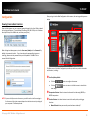
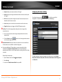
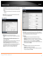
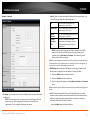
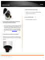
TRENDnet User’s Guide Cover Page TRENDnet User’s Guide Table of Contents Contents Product Overview .................................................................................... 2 Package Contents ...................................................................................................... 2 Features .................................................................................................................... 2 Product Hardware Features ....................................................................................... 3 Application Diagram .................................................................................................. 4 Installation ............................................................................................... 4 Hardware Installation ............................................................................................ 4 Camera Installation ............................................................................................... 5 Starting Camera Finder (IPSetup) ............................................................ 8 Configuration ......................................................................................... 10 Viewing Camera Basic Function................................................................................ 10 Configuring the Camera Setting ............................................................................... 11 Smart Wizard........................................................................................................... 12 Basic........................................................................................................................ 13 Network .................................................................................................................. 15 Video & Audio ......................................................................................................... 18 Event Server ............................................................................................................ 20 Motion Detect ......................................................................................................... 23 Event Config ............................................................................................................ 23 Tools ....................................................................................................................... 26 Device Info .............................................................................................................. 27 How to setup/access the camera behind a Router ................................ 28 Technical Specifications ......................................................................... 31 Troubleshooting..................................................................................... 32 © Copyright 2012 TRENDnet. All Rights Reserved. i TV-IP252P TRENDnet User’s Guide Features Product Overview The PoE Dome Internet Camera (model TV-IP252P) is designed for indoor enterprise class security surveillance applications. View and manage the tamper resistant dome IP camera from any Internet connection. Manually pan the camera side-to-side 350 degrees and tilt it up-and-down 160 degrees to fix its final viewing angle. No need to install this camera near a power source, power and data are received through a single Ethernet cable using Power over Ethernet (PoE) technology. Manage up to 32 TRENDnet cameras with the included complimentary camera management software. Advanced features include motion detection recording with two motion detection windows, email alerts, scheduled recording sessions, Samba client saves video to network storage devices, dual streaming MPEG-4/MJPEG image compression, two-way audio support (microphone and speaker sold separately), TV-IP252P Input/Output ports, digital zoom and an analog BNC video-out connector. A wall/ceiling mounting kit is included and the off-white IP camera housing blends into most Package Contents TV-IP252P Multi-Language Quick Installation Guide CD-ROM (Utility, Software &User’s Guide) Network cable (1.5m / 5ft) Power adapter (12V DC, 1.5A) Camera mounting kit environments. * TRENDnet’s Mobile APP supports iPhone®, iPad®, iPod® Touch and Android. Search for SecurView Mobile from iTunes® or Google Play™. For future updates, please check www.trendnet.com/App for details. ** Monitoring multiple cameras may required a high performance CPU If any package contents are missing or damaged, please contact the retail store, online retailer, or reseller/distributor that the item was purchased. © Copyright 2012 TRENDnet. All Rights Reserved. 2 TV-IP252P TRENDnet User’s Guide Product Hardware Features Inside Component Ethernet/PoE Port: Connect the provided network cable (RJ-45 type). The connector supports Power over Ethernet standard (PoE), enabling the camera to be powered by the Ethernet. Power: Connect the provided power adapter to supply power to the camera if Lens Focus Adjustment: Adjust the focus either clockwise or counter clockwise. Reset button: Press the button to restart the camera. Press and hold the button for five seconds, the camera will resume the factory default settings. LED indicators: Indicates the camera is powered on with the steady amber light and the link activity with blinking green light Link & Power switches: not using PoE. GPIO: Connected the provided external GPIO connector to the device, and then connect the external device (such as motion detection, event triggering or alarm system) to GPIO adapter. BNC connector: Connect the external monitor to BNC connector Mic In: Connect an external microphone. Speaker Out: Connects an external speaker. The two switches allow you to manually turn of the LED indicators. © Copyright 2012 TRENDnet. All Rights Reserved. 3 TV-IP252P TRENDnet User’s Guide Application Diagram Installation Hardware Installation The camera can be mounted to the ceiling surface directly by following the steps below: 1. Remove the Dome cover by unscrewing the four screws. 2. Use the included drill template to drill three mounting holes on the desire location and hammer the plastic anchors into the holes. © Copyright 2012 TRENDnet. All Rights Reserved. 4 TV-IP252P TRENDnet User’s Guide Camera Installation 3. Secured the camera to the location with three screws. 1. Insert the Installation CD-ROM into your computer’s CD-ROM drive to initiate the Auto-Run program. 2. Click the Install Camera. 4. Before put the Dome cover back, adjust the lens assembly by the following steps: Tilt the camera lens to a proper position by loosing the screws () and then swinging the adjustable base (). Rotate the camera lens by turning the base pedestal () in either clockwise or counter clockwise direction. Adjust the lens focus by turning the lens ring slowly () in either clockwise or counter clockwise direction. NOTE: You can review the image quality from the Web browser when you complete the installation. If the image quality is poor, you have to disassemble the Dome cover to adjust the lens focus until the desired image appears clearly. 5. Put the Dome cover back and secure with four screws. © Copyright 2012 TRENDnet. All Rights Reserved. 5 TV-IP252P TRENDnet User’s Guide 3. Write down the MAC ID of the camera 5. Connect a network cable to the camera’s network port and then to your router. If you are using the PoE, please ensure the cable is connected to a PoE switch or PoE injector. 4. If you are using PoE to supply power to camera, please skip to the next step. To power up the camera, plug in and connected the power adapter to the camera. You can verify the power connection by checking the amber LED on the camera. 6. Wait while the utility is searching the cameras. © Copyright 2012 TRENDnet. All Rights Reserved. 6 TV-IP252P TRENDnet User’s Guide 7. The founded cameras will show on the screen. The camera already selected by default if you have only one camera installed. If you have more than one camera in the same Network, you will need to identify the camera by the MAC ID. 9. Click here on the screen to access the camera now or click Next button for later accessing. 10. Click Finish to exit the program or click Home return to the main screen. 8. Type in the Password. The password is “admin” by default. We strongly suggested changing the camera’s password. The Change Password option is enable by default. © Copyright 2012 TRENDnet. All Rights Reserved. 7 TV-IP252P TRENDnet User’s Guide Starting Camera Finder (IPSetup) 3. Click the IPSetup from the Auto-Run menu screen. Then the IPSetup Wizard will appear. Click Install to install the utility. 4. When the Completing the IPSetup Setup Wizard appears, click Finish. The camera comes with a conveniently utility, IPSetup, which is included in the Installation CD-ROM, allowing you to search the camera on your network easily. 1. 2. Insert the Installation CD-ROM into your computer’s CD-ROM drive to initiate the Auto-Run program. Click the Camera Finder (IPSetup) from the Auto-Run menu screen. © Copyright 2012 TRENDnet. All Rights Reserved. 8 TV-IP252P TRENDnet User’s Guide 5. After installing the IPSetup utility, the application is automatically installed to your computer, and creates a folder in Start\Program\TRENDnet\IPSetup. 6. Click Start>Programs>TRENDnet>IPSetup, and then click IPSetup. 7. - Camera Display Area: By default, the IP setting on the Camera is set to DHCP. If you have DHCP server, the camera will automatic get the IP address from DHCP server. If you do not have DHCP server on your network, it will show the default IP as 192.168.10.30. Double click the IP address; it will link to Camera’s Web Configuration page. - Change IP: Click this button to bring up the following window. It allows you to change the IP Address. You can select either Static IP or click DHCP. Then, enter the Administrator ID & Password. By default the ID/Password is: admin. When complete, click Change. - Search: Click this button to search the connected camera in the same network - Exit: Click this button to exit the program. The IPSetup window will appear. It will search for the camera within the same network. Camera Display Area © Copyright 2012 TRENDnet. All Rights Reserved. 9 TV-IP252P TRENDnet User’s Guide Configuration After you login into the Web Configuration of the camera, the main page will appear as below: Viewing Camera Basic Function Open the Web browser on your computer (example showed in the User’s Guide is based on the Internet Explorer). Type the default IP address (192.168.10.30) or the IP address found by IPSetup in the Address bar, and then press [Enter]. When the login window appears, enter the User name (admin) and the Password. By default, the password is admin. If you have change the password during camera installing, please enter the password that you have updated. Click OK to link to camera’s Web Configuration. The Main screen of the Web Configuration provides you with many useful information and functions, including: Live View/Setup Switch: Click the button to configure the camera. Click the view image. button to return to the Main screen to view the live Compression Buttons: Select to transmit and record the video using MPEG4, or MJPEG compression. NOTE: If you are initially access to the camera, you will be ask to install a new plug-in for the camera. Permission request depends on the Internet security settings of your computer. Click Yes to proceed. Function Buttons: Use these buttons to control the audio, video, and trigger functions. Manual Record allows you manually record and save a video clip*. © Copyright 2012 TRENDnet. All Rights Reserved. 10 TV-IP252P TRENDnet User’s Guide Snapshot allows you to capture and save a still image*. Browse allows you to assign the destination folder to store the video clips and still images*. Talk allows you to speak out through the camera. Please note only one user is allowed to use this function at a time. Listen allows you to receive the on-site sound and voice from the camera. Trigger Out allows you to trigger on/off the GPIO output manually. Configuring the Camera Setting To configure the camera, click on the Main screen of Web Configuration. The Web Configuration will start from the Basic page. Live View: The Live View Image window displays the real-time image of the connected camera. The current compression mode of image is displayed above the Live View Image window. Click the Zoom In buttons above the Live View Image window to zoom in the live view image by 1x, 2x, or 3x. Camera Information: Displays the camera’s location and the current date & time. The information can be modified in the Web Configuration. If you are using Microsoft 7/Vista platform, you may not be able to find the recorded files by Snapshot or Manual Record. You will need to disable the protected mode of Security in the IE browser before recording a video file or taking a snapshot. Please follow the below steps: 1. Open IE Browser then select Tools Internet Options 2. Select Security The Web Configuration contains the settings in the left menu bar, including Smart Wizard, Basic, Network, Video/Audio, Event Server, Motion detect, Event Config, Tools, and Device Info. 3. Uncheck the ”Enable Protected Mode” then press OK © Copyright 2012 TRENDnet. All Rights Reserved. 11 TV-IP252P TRENDnet User’s Guide Smart Wizard IP Setting Select the IP setting according to your network: DHCP, Static IP, or PPPoE. The camera’s Smart Wizard lets you configure your camera easily and quickly. The wizard will guide you through the necessary settings with detailed instructions on each step. To start the wizard, click Smart Wizard in the left menu bar. Camera Setting By default, the camera name is set as model number. Change the name if necessary. Enter the location and administrator password twice. It is stronger recommend that you change the admin password. Email Settings Enter the required information to be able to send email with image. For example, myserver.com. If you are using a free mail service (e.g. Google Gmail®, Yahoo®, Hotmail®), please enter the SMTP server address and the corresponding information from the service provider. © Copyright 2012 TRENDnet. All Rights Reserved. 12 TV-IP252P TRENDnet User’s Guide Confirm Settings Basic The last step shows the configuration of your camera. When you confirm the settings, click Apply to finish the wizard and reboot the camera. Otherwise, click Prev to go back to the previous step(s) and change the settings; or click Cancel to end the wizard and discard the changes. The Basic menu contains three sub-menus that provide the System settings for the camera, such as the Camera Name, Location, Date & Time, and User management. Basic >> System Basic: This item allows you to assign the camera name and location information. © Copyright 2012 TRENDnet. All Rights Reserved. 13 TV-IP252P TRENDnet User’s Guide - Camera Name: Enter a descriptive name for the camera, which is helpful to identify the camera easily while multiple cameras are connected within the network. Location: Enter a descriptive name for the location where is monitored by the camera. Basic >> User Indication LED: This item allows you to set the LED illumination as desired. There are two options: Normal and OFF. Basic >> Date & Time Date & Time: Enter the correct date and time for the system. - TimeZone: Select the proper time zone for the region from the pull-down menu. - Automatically adjust clock for daylight saving time changes: select this option for daylight saving - Synchronize with PC: Select this option and the date & time settings of the camera will be synchronized with the connected computer. - Synchronize with NTP Server: Select this option and the time will be synchronized with the NTP Server. You need to enter the IP address of the server and select the update interval in the following two boxes. - Manual: Select this option to set the Date and Time manually. Administrator: To prevent unauthorized access to the camera’s Web Configuration, you are strongly recommend to change the default administrator password. Type the administrator password twice to set and confirm the password. General User - User Name: Enter the user’s name you want to add to use the camera. - Password: Enter the password for the new user. When you are finished, click Add/Modify to add the new user to the camera. To modify the user’s information, select the one you want to modify from UserList and click Add/Modify. - UserList: Display the existing users of the camera. To delete a user, select the one you want to delete and click Delete. Guest - User Name: Enter the guest’s name you want to add to use the camera. - Password: Enter the password for the new guest. - UserList: Display the existing guests of the camera. To delete a user, select the one you want to delete and click Delete. © Copyright 2012 TRENDnet. All Rights Reserved. 14 TV-IP252P TRENDnet User’s Guide NOTE: The “General User” is allowed to access the camera and control the Function buttons on the Main screen of the Web Configuration.; the “Guest” can only view the live view image from the Main screen while accessing the camera. Only the “Administrator” is allowed to configure the camera through the Web Configuration. Direct Video Stream Authentication: Network The Network menu contains two sub-menus that provide the networking settings for the camera, such as the IP Setting, DDNS Setting, UPnP, Bonjour, Port Number and IP Filter. To steam the video directly without going through the configuration page, you can access it via Internet. - Enable: User needs to enter user name and password to stream the camera. - Disable: User can stream the camera without entering the user name and password. Examples of the direct link to video: MPEG4 Mode http://camera_ip_address:port number/mpgview.htm MJPEG Mode http://camera_ip_address:port number/jpgview.htm NOTE This feature is enabled by default, and for security reason, it is recommended to have the feature enabled at all time. © Copyright 2012 TRENDnet. All Rights Reserved. 15 TV-IP252P TRENDnet User’s Guide Network >> Network - Static IP: Select this option to assign the IP address for the camera directly. You can use IP Setup to obtain the related setting values. IP Enter the IP address of the camera. The default setting is 192.168.10.30. Subnet Mask Enter the Subnet Mask of the camera. The default setting is 255.255.255.0. Default Gateway Enter the Default Gateway of the camera. The default setting is 192.168.10.1. Primary/ Secondary DNS DNS (Domain Name System) translates domain names into IP addresses. Enter the Primary DNS and Secondary DNS that are provided by ISP. - PPPoE: Select this option when you use a direct connection via the ADSL modem. You should have a PPPoE account from your Internet service provider. Enter the User Name and Password. The camera will get an IP address from the ISP as starting up. NOTE: Once the camera get an IP address from the ISP as starting up, it automatically sends a notification email to you. Therefore, when you select PPPoE as your connecting type, you have to set up the email or DDNS configuration in advance. DDNS Setting: With the Dynamic DNS feature, you can assign a fixed host and domain name to a dynamic Internet IP address. To set up the DDNS: 1. Select the Enable option to enable this feature. 2. Select the Provider from the pull-down list. 3. Enter the required information in the Host Name, User Name, and Password boxes. NOTE: You have to sign up for DDNS service with the service provider before configuring this feature. IP Setting: This item allows you to select the IP address mode and set up the related configuration. - DHCP: Select this option when your network uses the DHCP server. When the camera starts up, it will be assigned an IP address from the DHCP server automatically. This is the default IP setting on the camera. UPnP: The camera supports UPnP (Universal Plug and Play), which is a set of computer network protocols that enable the device-to-device interoperability. In addition, it supports port auto mapping function so that you can access the camera if it is behind an NAT router or firewall. Select the Enable option to enable this feature. © Copyright 2012 TRENDnet. All Rights Reserved. 16 TRENDnet User’s Guide UPnP Port Forwarding: select this option to have the port forward to router. Bonjour: The devices with Bonjour will automatically broadcast their own services and listen for services being offered for the use of others. If your browser with Bonjour, you can find the camera on your local network without knowing its IP address. The Apple Safari is already with Bonjour. You can download the complete Bonjour for Internet Explorer browser from Apple's web site by visiting http://www.apple.com/bonjour/. Ports Number - HTTP Port: The default HTTP port is 80. - RTSP Port: Configure the transmission of streaming data within the network. The default RTSP (Real Time Streaming Protocol) port is 554. NOTE: If the camera is behind an NAT router of firewall, the suggested to be used is from 1024 to 65535. Network >> IP Filter TV-IP252P select the Deny option to assign the range of IP addresses that are blocked to access the camera. Disable: Select this option to disable the IP Filter function of the camera. Accept - Assign a range of IP addresses that are allowed to access the camera by entering the Start IP address and End IP address options. When you are finished, click Add to save the range setting. You can repeat the action to assign multiple ranges for the camera. For example, when you enter 192.168.10.50 in Start IP Address and 192.168.10.70 in End IP Address, the user whose IP address located within 192.168.10.50 ~ 192.168.10.70 will be allowed to access the camera. Accept IP List: The list displays the range setting(s) of IP addresses that are allowed to access the camera. To clear the setting, select a range of IP addresses from the list and click Delete. Deny - Assign a range of IP addresses that are blocked to access the camera by entering the Start IP address and End IP address options. When you are finished, click Add to save the range setting. You can repeat the action to assign multiple ranges for the camera. For example, when you enter 192.168.10.50 in Start IP Address and 192.168.10.70 in End IP Address, the user whose IP address located within 192.168.10.50 ~ 192.168.10.70 will not be allowed to access the camera. Deny IP List: The list displays the range setting(s) of IP addresses that are blocked to access the camera. To clear the setting, select a range of IP addresses from the list and click Delete. The IP Filter setting allows the administrator of the camera to limit the users within a certain range of IP addresses to access the camera. To disable this feature, select the Disable option; otherwise, select the Accept option to assign the range of IP addresses that are allowed to access the camera, or © Copyright 2012 TRENDnet. All Rights Reserved. 17 TV-IP252P TRENDnet User’s Guide Video & Audio Video & Audio >> Video The Video & Audio menu contains four sub-menus that provide the video and audio settings for the camera. Video & Audio >> Camera Image Setting - Brightness: Adjust the brightness level from 0 ~ 100. - Saturation: Adjust the colors level from 0 ~ 100. - Sharpness: Adjust the sharpness level from 0 ~ 100. Click Default to restore the default settings of the three options above. - Mirror: Select Vertical to mirror the image vertically, or select Horizontal to mirror the image horizontally. MPEG4 - Video Resolution: Select the desired video resolution from the three formats: VGA, QVGA, and QQVGA. The higher setting (VGA) obtains better video quality while it uses more resource within your network. - Video Quality: Select the desired image quality from five levels: Lowest, Low, Medium, High, and Highest. - Frame Rate: Select a proper setting depending on your network status. MJPEG - Video Resolution: Select the desired video resolution from the three formats: VGA, QVGA, and QVGA. The higher setting (VGA) obtains better video quality while it uses more resource within your network. - Video Quality: Select the desired image quality from five levels: Lowest, Low, Medium, High, and Highest. - Frame Rate: Select a proper setting depending on your network status. © Copyright 2012 TRENDnet. All Rights Reserved. 18 TV-IP252P TRENDnet User’s Guide - None IE Browser Viewer: Select the proper mode for viewing image while using none IE browser: Java Applet, Still Image, or Server Push. Video & Audio >> Text Overlay NOTE: The camera supports both MPEG4 and MJPEG compression. MJPEG capture the images in JPEG format, which require higher bandwidth to view smooth video. The administrator can control the bandwidth of each connection well through the setting options above. 3GPP: The camera supports 3GPP specification. To disable this feature, select the Disable option; otherwise, select 3GPP Without Audio or 3GPP With Audio to transfer the video clips without or with audio. If you use a mobile phone that supports 3GPP, you can also view the real-time streaming image captured by the camera on your phone (with the default player on the phone) by entering the RTSP link: rtsp://(IP address of the camera)/3gp. Video & Audio >> Audio Include Date & Time: Select this option to display the date & time information on the live view image. Include Text: Select this option and enter your heading text in the box to display the text information on the live view image. Enable Opaque: Select this option to display the overlay text with a background color. For example, when you select the Include Date & Time and Include Text options and click Apply, you can see the related information displayed on the live view image when you click the button. Camera Microphone In: Select the Enable option to enable the camera’s audio function, so that you can receive the on-site sound and voice from the camera. Camera Speaker Out: Select the Enable option to enable the camera’s external speaker function, so that the connected speaker can play the sound and voice through the camera. You can set the speaker’s volume by entering the proper value in the Volume option. The default setting is 90. © Copyright 2012 TRENDnet. All Rights Reserved. 19 TV-IP252P TRENDnet User’s Guide Event Server HTTP Notify For Motion Trigger The Event Server menu contains three sub-menus that allow you to upload images to FTP, send emails that include still images, and store the images to a NAS system. Send the query parameter via an HTTP notification when an event is triggered. - Host: Enter the IP of the HTTP server Port: Enter the Port number of the HTTP server User Name: Enter the username of the HTTP server Password: Enter the password of the HTTP server Query: Enter the query parameter for the request if necessary Example: Host: 192.168.10.1 Port: 80 Query: xxx.cgi?name1=value1&name2=value2 Example: cgi/event.cgi?status=#s&time=#t&model=modelname Result: http://192.168.10.1:80/cgi/event.cgi?status=#s&time=#t&model=modelname When you complete the required settings for HTTP Notify for Motion Trigger, FTP, Email, or Network Storage, click Test to test the related configuration is correct or not. Once the camera connects to the server successfully, click Apply. © Copyright 2012 TRENDnet. All Rights Reserved. 20 TV-IP252P TRENDnet User’s Guide Event Server Setting >> FTP FTP - Host Address: Enter the IP address of the target FTP server. Port Number: Enter the port number used for the FTP server. User Name: Enter the user name to login into the FTP server. Password: Enter the password to login into the FTP server. Directory Path: Enter the destination folder for uploading the images. For example, /test. - Passive Mode: Select the Enable option to enable passive mode. - FTP Upload With: Set the format of the image that is to be uploaded to the FTP server. You can set the format as One Snapshot or images containing Pre-event (0 ~ 3 seconds) and Post-event (0 ~ 3 seconds). Event Server Setting >> Email Email - SMTP Server Address: Enter the mail server address. For example, myserver.com. If you are using a free mail service (e.g. Google Gmail®, Yahoo®, Hotmail®), please enter the SMTP server address from the service provider. - Port Number: Assign the port number in the text box. The default port is 25. For the free mail service, please enter the correct port number from the service provider. - SSL: If the mail server requires an encrypted connection, you should select the SSL option. - STARTTLS is an extension to plain text communication protocols. It offers a way to upgrade a plain text connection to an encrypted connection. © Copyright 2012 TRENDnet. All Rights Reserved. 21 TRENDnet User’s Guide - - - Sender Email Address: Enter the email address of the user who will send the email. For example, [email protected]. Authentication Mode: Select None to disable the authentication feature, or select SMTP and then enter the User Name and Password according to the mail server configuration. Sender User Name: Enter the user name to login the mail server. Sender Password: Enter the password to login the mail server. Receiver #1 Email Address: Enter the first email address of the user who will receive the email. Receiver #2 Email Address: Enter the second email address of the user who will receive the email. Send Email With: Set the format of the image that is to be sent by the email. You can set the format as One Snapshot or images containing Pre-event (0 ~ 3) seconds and Post-event (0 ~ 3) seconds. TV-IP252P - Path: Assign the path for uploading the files on the Network Storage server. For example, Test. - User Name: Enter the user name to login into the Network Storage server. - Password: Enter the password to login into the Network Storage server. - Split By: When the file is too large to upload smoothly, use this option to split it by selecting File Size or Recording Time. - When Storage Full: Select Stop Recording or Recycle - Delete Oldest Folder when the storage space on the Network Storage server is full. - Encode Format: Select MPEG4 or H.264 as the encode format while recording. - File Format: Select MP4 or AVI as the file format while recording. WAN IP Change Notify: Select the option to enable the system to notify you when the WAN IP address changed. Event Server Setting >> Network Storage Network Storage - Samba Server Address: Enter the IP address of the Network Storage server. - Share: Assign the folder on the Network Storage server to share the files to users. © Copyright 2012 TRENDnet. All Rights Reserved. 22 TV-IP252P TRENDnet User’s Guide Motion Detect Event Config The Motion Detect menu contains the command and option that allow you to enable and set up the motion detection feature of the camera. The camera provides two detecting areas. The Event Config menu contains five sub-menus that provide the commands to configure event profiles. To enable the detecting area, select Window 1 or 2 from the pull-down list, and then select Enable. When the detecting area is enabled, you can use the mouse to move the detecting area and change the area coverage. Name: Assign a name to the detecting area. Threshold: Move the slide bar to adjust the level of motion detection on recording video. NOTE: Sliding the Threshold bar to the right will decrease the sensitivity of motion detection; sliding the Threshold bar to the left will increase the sensitivity of motion detection. © Copyright 2012 TRENDnet. All Rights Reserved. 23 TRENDnet User’s Guide TV-IP252P Event Configuration >> General Setting General - Snapshot/Recording Subfolder: You can assign a given subfolder to each new captured file. Otherwise, leave this option blank to use the default setting. - Network Storage Recording Time Per Event: Limit the recording time while you are using the Network Storage solution. Event Configuration >> Schedule Profile Schedule Profile: This sub-menu displays the scheduled profile(s). To customize the profile, click Add and then enter a descriptive name for the profile in the prompt dialog window. After entering the profile name, click OK and the profile is added to the Schedule Profiles list. - Profile Name: Display the profile name that you select in the Schedule Profiles list. - Weekdays: Select the weekday(s) that you want to separately assign in the schedule profile. The weekday that has been assigned will be displayed with green color. - Time List: Display the time period that you have assigned within the selected weekday. To assign the same time period to every weekday, click Add this to all weekdays; click Delete this from all weekdays to remove the selected time period from every weekday. Click Delete to remove the selected time period. - Start/End Time: Enter the start and end time and then click Add to assign a time period within in the selected weekday. To delete the profile, select the profile in the list and click Delete. © Copyright 2012 TRENDnet. All Rights Reserved. 24 TV-IP252P TRENDnet User’s Guide Event Configuration >> Motion Detect Trigger Motion Detect Profile: Select the Enable option to enable the trigger function of the camera, so that you can send captured images within the detecting area to the FTP server, email receiver, or the Network Storage server. You have to configure corresponding settings, such as FTP server and email server, to enable this feature. Please note that you have to configure the related settings before enabling these features. - Schedule Profile: Select a schedule profile from the pull-down list. - Action: Select the destination that the captured images will be sent to: Record to Network Storage, Send Email, FTP Upload, or HTTP Notify. Event Configuration >> Schedule Trigger You can separately configure the schedule for trigger function of the camera by Email, FTP, or Network Storage. Select the Enable option on each item, and then select a Schedule Profile from the pull-down list and set the Interval time. NOTE: If the setting value of the Network Storage Recording Time Per Event option in General Setting is longer than the Interval time in Network Storage Schedule, the recorded file will be a continuous video clip. For example, if you set the Network Storage Recording Time Per Event as 10 seconds and the Interval as 5 seconds, recorded file becomes a non-stop video clip because the camera will record a 10-second video clip every 5 seconds. © Copyright 2012 TRENDnet. All Rights Reserved. 25 TV-IP252P TRENDnet User’s Guide Event Configuration >> GPIO Trigger Tools The Tools menu provides the commands that allow you to restart or reset the camera. You can also backup and restore your configuration, and upgrade the firmware for the camera. The GPIO trigger function of the camera allows you to set Trigger Out function or send captured images within the detecting area to the Network Storage server, email, FTP or HTTP notify. You have to configure corresponding settings, such as Network Storage Server, FTP server and email server, to enable this feature. Enable Trigger In 1 or 2: Select the option to enable the GPIO trigger function of the camera. Then, complete the following options - Schedule Profile: Select a schedule profile (Always, or the profile you have set) from the pull-down list. - Action: Select the Trigger Out function or select the destination of the captured image (Record to Network Storage, Send Email, FTP Upload or HTTP Notify). Factory Reset: Click Reset to restore all factory default settings for the camera. System Reboot: Click Reboot to restart the camera just like turning the device off and on. The configuration of the camera will be retained after rebooting. Configuration: You can save your camera configuration as a backup file on your computer. Whenever you want to resume the original settings, you can restore them by retrieving the backup file. - Backup: Click Get the backup file to save the current configuration of the camera. - Restore: Click Browse to locate the backup file and then click Restore. © Copyright 2012 TRENDnet. All Rights Reserved. 26 TV-IP252P TRENDnet User’s Guide Update Firmware: You can upgrade the firmware for your camera once you obtained a latest version of firmware. - Current Firmware Version: This item displays the current firmware version. - Select the firmware: Click Browse to locate the backup file and then click Update. Device Info >> Device Info Display the Basic, Video & Audio, and Network settings of the camera. NOTE: Make sure to keep the camera connected to the power source during the process of upgrading firmware. Otherwise, the camera might be damaged because of failure of upgrading firmware. Device Info The Information menu displays the current configuration and events log of the camera. Device Info >> System Log The Logs table displays the events log recorded by the system. © Copyright 2012 TRENDnet. All Rights Reserved. 27 TV-IP252P TRENDnet User’s Guide How to setup/access the camera behind a Router 4. Open another web browser and go to your Router’s Web Configuration page. (In the example, TRENDnet’s TEW-651BR Wireless N router is used) You can either setup the Dynamic DNS connection via camera itself or your home router. An account from any of the listed DDNS providers is required prior to this operation. Configure DDNS on your Camera 1. Go to Camera’s DDNS Setting page, click Enable to activate the feature. Then select a DDNS provider from the list. 2. Enter your DDNS’s the Host Name, User Name and Password. 3. In the Port Number section, assign an HTTP port of the camera. The default HTTP Port on the camera is 80. The example shows above is using port number 9000. © Copyright 2012 TRENDnet. All Rights Reserved. 28 TV-IP252P TRENDnet User’s Guide 5. Go to Virtual Server* section and create a new entry. Enable: Click Enable Name: Enter the application name (eg. CameraName) Protocol: Select TCP Private Port: The HTTP port that you assign on your Camera. Public Port: The port used on remote side to access to your Camera. LAN Server: The local IP address of your Camera. 6. Open another web browser and enter your DDNS domain and camera’s port number. http://yourDomainName:PortNumber 7. Camera’s login page will appear. Configure DDNS on your router 1. Go to Camera’s DDNS Ports Number section, assign a HTTP port for your camera and click Apply. 2. Login to your router’s web configuration page. Then click Add to add the application. * Please refer to your router’s user’s manual for detail Virtual Server setting. Some router might use Port Forwarding or Special applications for this function. The setup steps should be very similar. © Copyright 2012 TRENDnet. All Rights Reserved. 29 TV-IP252P TRENDnet User’s Guide 3. Find the Dynamic DNS configuration section. 5. Go to Virtual Server* section and create a new entry. Enable: Click Enable Name: Enter the application name (eg. Camera Name) Protocol: Select TCP Private Port: The HTTP port that you assign on your Camera. Public Port: The port used on remote side to access to your Camera. LAN Server: The local IP address of your Camera. Click Add to add the application. 4. Enable DDNS, fill out the following information and then click Apply. * Please refer to your router’s user’s manual for detail Virtual Server setting. Some router might use Port Forwarding or Special applications for this function. The setup steps should be very similar. 6. Open another web browser and enter your DDNS domain and camera’s port number. http://yourDomainName:PortNumber 7. The camera login page will appear. © Copyright 2012 TRENDnet. All Rights Reserved. 30 TV-IP252P TRENDnet User’s Guide Technical Specifications Power Input: 100 ~ 240V AC , 0.5A, 50~60Hz Output: 12VDC 1.5A external power adapter (for non-PoE installations) Camera General Sensor: 1/4” Megapixel CMOS sensor Max. Resolution: 640 x 480 pixels Board Lens Focal Length: 3.58 mm Aperture (F/No): F2.0 +/- 5% Minimum illumination: 0.1 Lux @ F2.0 Viewing Angle - Horizontal: 69.3 degree - Vertical: 58.1 degree - Diagonal: 44.8 degree Audio Microphone In port (microphone sold separately) Audio out port: Mono (speakers sold separately) Sensitivity: -42dB +/- 3dB Frequency: 100~10,000Hz S/N: 65dB Format: PCM/AMR Pan/Tilt (Manually) Dimension 140 x 120 x 140 mm (5.2 x 4.7 x 5.5 in.) Weight 600 g (21.2oz.) Temperature Operating: 0C ~ 45C (32F ~ 113F) Storage: -15C ~ 60C (5F ~ 140F) Humidity Max. 90% (non-condensing) Certifications CE, FCC Requirement Management Interface Internet Explorer 7.0 or above To Run SecurView Pro Windows 7 (32/64-bit), Vista (32/64-bit), XP (32/64bit) Windows Server 2003, 2008 SecurView Pro Channel: supports up to 32 cameras Record/Playback/Motion Detection/Audio Manually adjust camera to final fixed position: Network Protocols Pan: -175° ~ +175° Tilt: 20 ~ 90° Rotate: -90° ~ +90° Management Hardware Network IEEE 802.3u 10/100Mbps Fast Ethernet IEEE 802.3af PoE LED Power, Link/Act (can turn off LEDs) Reset Button Reboot or restore to factory default Power Consumption 8 watts max. TCP/IP, IPv4, UDP, ICMP, DHCP, NTP, DNS, DDNS, SMTP, FTP, HTTP, HTTPs, Samba, PPPoE, UPnP, Bonjour, RTP, RTSP, RTCP, SSL, and 3GPP Remote Remote management supported Backup / Restore Save/retrieve configuration files Settings Image Brightness, saturation, sharpness, and mirror (horizontal/vertical) Video Encoding type: MPEG-4, MJPEG Compression: 5 levels © Copyright 2012 TRENDnet. All Rights Reserved. 31 TV-IP252P TRENDnet User’s Guide Resolution/Frame Rate: VGA (640x480) up to 30fps QVGA (320x240) up to 30fps QQVGA (160x120) up to 30fps Recording / snapshot Recording type: continuous, schedule, motion detection, or snapshot Event Management Event trigger: motion, schedule Store video file to storage device Overlay Text overlay: time, date, and text Port Settings HTTP port: 80 (default) Troubleshooting 1. Windows 7 If the installation menu does not appear automatically, click on the Windows Icon on the bottom left hand corner of the screen, click the “Search programs and files” box, and type D:\autorun.exe, where “D” in “D:\autorun.exe” is the letter assigned to your CD-ROM Drive, and then press the ENTER key on your keyboard . RTSP port: 554 (default) Digital Zoom 3x Dynamic DNS Yes Time Synchronize with NTP server or set time/date manually Email Supports up to 2 destination accounts System Log 100 entries (max.) I inserted the Utility CD-ROM into my computer's CD-ROM Drive but the installation menu does not appear automatically. What should I do? Windows Vista If the installation menu does not appear automatically, click Start, click the Start Search box, and type D:\autorun.exe where "D" in "D:\autorun.exe" is the letter assigned to your CD-ROM Drive, and then press the ENTER key on your keyboard. Windows XP If the window does not appear automatically, click Start, click Run and type D:\autorun.exe where “D” in “D:\autorun.exe” is the letter assigned to your CD-ROM Drive, and then press the ENTER key on your keyboard. 2. IP Setup is unable to detect my camera. What should I do? a. b. c. d. Verify that you have followed all the steps in Section 2: Hardware Installation. Disable any software firewall programs such as ZoneAlarm or Norton Internet Security. If you are using Windows 7, Vista or XP, disable the built in firewall. Click on Search in IPSetup. Reset the IP Camera by remove the top cover and press the reset button © Copyright 2012 TRENDnet. All Rights Reserved. 32 TV-IP252P TRENDnet User’s Guide 5. When I click on Live View the image does not load? a. b. 6. Make sure that you are using a browser that supports ActiveX. Make sure that ActiveX is installed. Can I use the TV-IP252P outdoor? The TV-IP252P was designed for indoor use only. 3. I do not have a DHCP server or DHCP is disable on my network and I am unable to configure the TV-IP252P. What should I do? a. b. 4. Go to the TCP/IP settings on your computer and assign a static IP address on your computer’s network adapter in the subnet of 192.168.10.x. Since the default IP address of the TV-IP322P is 192.168.10.30, do not assign a static IP address of 192.168.10.30 on your computer’s network adapter. Open Internet Explorer and enter http://192.168.10.30 into the address bar. The image is blurry. How can I adjust the focus on the IP camera? Remove the cover on the top of the TV-IP252P. You can adjust the Internet Camera’s focus by rotating the Lens (Please refer to Cameo Focus on page 6 for more detail). © Copyright 2012 TRENDnet. All Rights Reserved. 33 TRENDnet User’s Guide Limited Warranty TRENDnet warrants its products against defects in material and workmanship, under normal use and service, for the following lengths of time from the date of purchase. TV-IP252P – 3 Years Limited Warranty AC/DC Power Adapter, Cooling Fan, and Power Supply carry 1 year warranty. If a product does not operate as warranted during the applicable warranty period, TRENDnet shall reserve the right, at its expense, to repair or replace the defective product or part and deliver an equivalent product or part to the customer. The repair/replacement unit’s warranty continues from the original date of purchase. All products that are replaced become the property of TRENDnet. Replacement products may be new or reconditioned. TRENDnet does not issue refunds or credit. Please contact the point-of-purchase for their return policies. TRENDnet shall not be responsible for any software, firmware, information, or memory data of customer contained in, stored on, or integrated with any products returned to TRENDnet pursuant to any warranty. There are no user serviceable parts inside the product. Do not remove or attempt to service the product by any unauthorized service center. This warranty is voided if (i) the product has been modified or repaired by any unauthorized service center, (ii) the product was subject to accident, abuse, or improper use (iii) the product was subject to conditions more severe than those specified in the manual. Warranty service may be obtained by contacting TRENDnet within the applicable warranty period and providing a copy of the dated proof of the purchase. Upon proper submission of required documentation a Return Material Authorization (RMA) number will be issued. An RMA number is required in order to initiate warranty service support for all TRENDnet products. Products that are sent to TRENDnet for RMA service must have the RMA number marked on the outside of return packages and sent to TRENDnet prepaid, insured and packaged appropriately for safe shipment. Customers shipping from outside of the USA and Canada are responsible for return shipping fees. Customers shipping from outside of the USA are responsible for custom charges, including but not limited to, duty, tax, and other fees. TV-IP252P WARRANTIES EXCLUSIVE: IF THE TRENDNET PRODUCT DOES NOT OPERATE AS WARRANTED ABOVE, THE CUSTOMER’S SOLE REMEDY SHALL BE, AT TRENDNET’S OPTION, REPAIR OR REPLACE. THE FOREGOING WARRANTIES AND REMEDIES ARE EXCLUSIVE AND ARE IN LIEU OF ALL OTHER WARRANTIES, EXPRESSED OR IMPLIED, EITHER IN FACT OR BY OPERATION OF LAW, STATUTORY OR OTHERWISE, INCLUDING WARRANTIES OF MERCHANTABILITY AND FITNESS FOR A PARTICULAR PURPOSE. TRENDNET NEITHER ASSUMES NOR AUTHORIZES ANY OTHER PERSON TO ASSUME FOR IT ANY OTHER LIABILITY IN CONNECTION WITH THE SALE, INSTALLATION MAINTENANCE OR USE OF TRENDNET’S PRODUCTS. TRENDNET SHALL NOT BE LIABLE UNDER THIS WARRANTY IF ITS TESTING AND EXAMINATION DISCLOSE THAT THE ALLEGED DEFECT IN THE PRODUCT DOES NOT EXIST OR WAS CAUSED BY CUSTOMER’S OR ANY THIRD PERSON’S MISUSE, NEGLECT, IMPROPER INSTALLATION OR TESTING, UNAUTHORIZED ATTEMPTS TO REPAIR OR MODIFY, OR ANY OTHER CAUSE BEYOND THE RANGE OF THE INTENDED USE, OR BY ACCIDENT, FIRE, LIGHTNING, OR OTHER HAZARD. LIMITATION OF LIABILITY: TO THE FULL EXTENT ALLOWED BY LAW TRENDNET ALSO EXCLUDES FOR ITSELF AND ITS SUPPLIERS ANY LIABILITY, WHETHER BASED IN CONTRACT OR TORT (INCLUDING NEGLIGENCE), FOR INCIDENTAL, CONSEQUENTIAL, INDIRECT, SPECIAL, OR PUNITIVE DAMAGES OF ANY KIND, OR FOR LOSS OF REVENUE OR PROFITS, LOSS OF BUSINESS, LOSS OF INFORMATION OR DATE, OR OTHER FINANCIAL LOSS ARISING OUT OF OR IN CONNECTION WITH THE SALE, INSTALLATION, MAINTENANCE, USE, PERFORMANCE, FAILURE, OR INTERRUPTION OF THE POSSIBILITY OF SUCH DAMAGES, AND LIMITS ITS LIABILITY TO REPAIR, REPLACEMENT, OR REFUND OF THE PURCHASE PRICE PAID, AT TRENDNET’S OPTION. THIS DISCLAIMER OF LIABILITY FOR DAMAGES WILL NOT BE AFFECTED IF ANY REMEDY PROVIDED HEREIN SHALL FAIL OF ITS ESSENTIAL PURPOSE. Governing Law: This Limited Warranty shall be governed by the laws of the state of California. Some TRENDnet products include software code written by third party developers. These codes are subject to the GNU General Public License ("GPL") or GNU Lesser General Public License ("LGPL"). © Copyright 2012 TRENDnet. All Rights Reserved. 34 Limited Warranty TRENDnet User’s Guide Go to http://www.trendnet.com/gpl or http://www.trendnet.com Download section and look for the desired TRENDnet product to access to the GPL Code or LGPL Code. These codes are distributed WITHOUT WARRANTY and are subject to the copyrights of the developers. TRENDnet does not provide technical support for these codes. Please go to http://www.gnu.org/licenses/gpl.txt or http://www.gnu.org/licenses/lgpl.txt for specific terms of each license. V1.0R / 10.16.2012 © Copyright 2012 TRENDnet. All Rights Reserved. 35