1
PMD-1208LS User's Guide
Functional Details
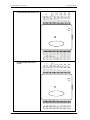
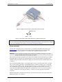
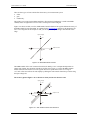
Figure 3-8. Digital connection Port A0 detecting the state of a switch
Port A0
+GND
+5V
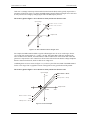
Figure 3-9. Schematic showing switch detection by digital channel Port A0
For more information on digital signal connections
For more information on digital signal connections and digital I/O techniques, refer to the Guide to Signal
Connections (available on our web site at www.mccdaq.com/signals/signals.pdf).
Power terminals
The PC +5 V connection (pin 30) is on the bottom screw terminal of the PMD-1208LS. Refer to the
pinout diagrams on page 3-4 for the location of this pin. This terminal draws power from the USB
connector. The +5 V screw terminal is a 5 volt output that is supplied by the host computer.
Caution! The +5V terminal is an output. Do not connect to an external power supply or you may
damage the PMD-1208LS and possibly the computer.
The maximum total output current that can be drawn from all PMD-1208LS connections (power, analog
and digital outputs) is 500 mA. This maximum applies to most personal computers and self-powered
USB hubs. Bus-powered hubs and notebook computers may limit the maximum available output current
to 100 mA.
Just connecting the PMD-1208LS to your computer draws 20 mA of current from the USB +5 V supply.
Once you start running applications with the PMD-1208LS, each DIO bit can draw up to 2.5 mA, and
each analog output can draw 30 mA. The maximum amount of +5 V current available for experimental
use, over and above that required by the PMD-1208LS, is the difference between the total current
requirement of the PMD (based on the application), and the allowed current draw of the PC platform
(500 mA for desktop PCs and self-powered hubs, or 100 mA for bus-powered hubs and notebook
computers).
With all outputs at their maximum output current, you can calculate the total current requirement of the
PMD-1208LS USB +5 V as follows:
3-8