1
C. SETTING THE SENSING FIELD
Guide pins
BFP1 U S E R ’ S G U I D E
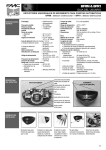
• To adjust the sensing field according to your specific needs, use the masking delivered in the sensor box;
The minimum detection area at mounting height of 2.2 m is 0.5 m x 0.5 m
THE MOST ADVANCED TECHNOLOGY IN PASSIVE INFRARED SENSOR RANGE
• To tailor the sensing field, cut segments
Remarks :
1) Be careful to cut just entire segments
2) It is necessary to cut at least one segment to get a detection
The BFP1 is designed for use in opening of automatic doors with small and medium sized sensing fields
It is not recommended for automatic doors with large sensing fields (BFR1 range is recommended) or automatic doors when shopping
carts or trolleys are used.
Cut-Out footprints
To insert the masking lens :
• Consider the position of the guide pins when inserting both legs of the masking lens to the front cover
• Gently push both legs of the masking lens
TECHNICAL
SPECIFICATIONS
To remove the masking lens :
• Insert the screwdriver between the leg of the masking lens and the leg of the front cover
• Use it as a lever downwards
SENSING FIELD
Technology
Optical characteristics
Passive infrared and microprocessor
P.I.R. with 4 elements, 15 Fresnel
lenses with full independent masking
possibilities
Mounting height
3 m max
Maximum Detection area for mounting height of 2.2m
2.5 m (W) x 1.5 m (D)
Minimum Detection area for mounting height of 2.2 m
0.5 m (W) x 0.5 m (D)
Detection mode
motion
Detection speed
0.1 to 1.5 m/s
Light indicator
1 red LED
Warm up
10 s
Hold time
0.5 s or 2 s
Response time
< 200 ms
Power supply
12 VDC –10% to 24 VDC +30%
12 to 24 V AC ±10%
Mains frequency
50/60 Hz
Power consumption
<1W
Connection
small plug-in 5 contacts connector
Recommended cable
section
< 0.5 mm2
Length of cable
2.5 m
Temperature range
from –30°C to +55°C
DESCRIPTION
The passive infrared
sensor
ASYMMETRICAL SENSING FIELD SHORTER DEPTH
DETECTION AREA
DETECTION AREA
door threshold
door threshold
FSA Accessory
for mounting on the wall
±10 cm
NO DETECTION
±10 cm
NODETECTION
SYMPTOMS
PROBABLE CAUSES
CORRECTIVE ACTIONS
The door will not open and the LED does not light up
The sensor is not properly powered
a. Check the power supply
b. Check the supplied voltage
The door will not open and the LED lights up
The wiring of the relay output is not
connected correctly
Check the relay wiring
The door opens when no detection occurs and closes
during a detection
The mode of the relay output is
not correct
Change the dip-switch #2 position
The sensing field does not correspond to your
requirements
The cut of the masking lens is wrong
Cut out a new lens to meet the required
sensing field size
42.0006/V1-12.01
732937 - Rev. A
TROUBLESHOOTINGS
FAAC S.p.A. - Via Benini, 1 40069 Zola Predosa - Italia - tel.+39 051 61724 - fax.+39 051 758518 - www.faacgroup.com
INSTALLATION
TIPS
• The sensor must be firmly
fastened in order to avoid any
vibrations
Standard output relay (free potential change-over contact)
• Max contact voltage 60 V DC/ 42 V AC
• Max contact current 1A (resistive)
• Max switching power 30W (DC) / 60 VA(AC)
Manual adjustments
• shape of sensing field (masking lens)
• sensitivity (dip switch #1)
• relay configuration (dip switch #2)
• Hold time (dip switch #3)
Immunity
electromagnetic compatibility (EMC)
according to 89/336/EEC and its
amendments.
• Color
• Weight
• Dimensions
anthracite grey
40g
121mm (W) x 51mm (H) x 40mm (D)
• Degree of protection
IP54
DESCRIPTION
OF
THE PRODUCT
AND
THE SENSOR
MOUNTING
THE SENSOR
Main cable
Unplug 5-wire connector
2 screws to fix the BFP1
2 brackets
Lens
2 screws to fix the brackets with
the BFP1
Masking Lens (2 units)
• Description of the product
1
2
12-24 V AC/DC
3
COM
4
NO
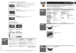
A. MOUNTING THE BFP1
5
NC
Wire Opening Footprints
• Wiring
Microprocessor
LED
Dip Switches
PYRO element
• Stick the template on the wall
• Drill the 2 holes to fix the FSA
and the hole for the cable
• Open the FSA (see page 2 :
opening and closing the FSA
Accessory)
• Cut the wire opening footprint
of the base
• Fix the sensor to the FSA base
with the 2 screws
• Connect the sensor to the cable
• Close the FSA (see page 2 :
opening and closing the FSA
Accessory)
Guide pins of the BFP1 base
Guide pins of the masking lens
Guide Pins of the BFP1 base
• Description of the sensor
• Inner view of the sensor front cover
OPENING
AND
CLOSING
THE SENSOR
• Use a small screwdriver to open the sensor
• Insert the screwdriver in the rectangular hole under the bracket cam
• Use it as a lever upwards
OPENING
AND
CLOSING
THE FSA
ACCESSORY
LED
SIGNAL
• The LED flashes for a few seconds when the sensor is switched on
• The LED lights up through the lens when the sensor detects motion
SETTING
OF
THE SENSOR
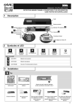
A.DIP SWITCHES SETTINGS AND RELAY CONFIGURATIONS
• Consider the position of the guide pin when inserting both legs of the
front cover to the base
• Gently push both sides of the front cover
OPENING THE FSA ACCESSORY
DIP SWITCHES
ON
OFF
Sensitivity high
Sensitivity low (recommended
for mounting height < 2,2 m)
2
Passive mode
Active mode
OFF
3
Hold time : 2 sec
Hold time : 0,5 sec
OFF
The relay configurations are :
• Either use the screwdriver to open the FSA (left picture)
• Or pinch off both sides of the front cover (right picture)
• Rotate the front cover upwards
CLOSING THE
DETECTION
ACTIVE MODE
NO DETECTION
COM (3)
NC (5)
NO (4)
COM (3)
COM (3)
NC (5)
1
NO (4)
NC (5)
NO (4)
NC (5)
B.SENSING FIELD POSITION
FRONT VIEW
PROFILE VIEW
2,2 m 3 m
2,2 m
ON
ON
PASSIVE MODE
NO (4)
COM (3)
FSA ACCESSORY
• Insert the bottom of the front cover to the bottom clip of the base
• Push on the top of the front cover face
FACTORY SETTING
1
3m
50 cm 50 cm 50 cm 50 cm 50 cm
2,5 m
50 cm 50 cm 50 cm
1,5 m depth
door
threshold
FLAT VIEW
1,5 m
2,5 m
height 2,2 m
2
3