1
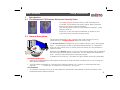
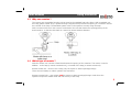
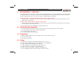
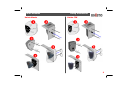
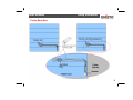
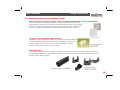
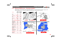
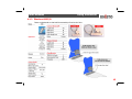
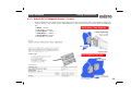
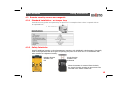
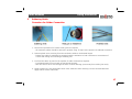
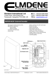
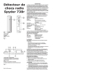
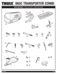
Unisto Remotes
Fitting Instructions
Remote
Installation
& User Guide
EP0027A_520Aa_en
6 October2009/SNO
Whilst every effort has been made to ensure that all information contained in this document is correct at the time of publication, due to our
policy of continuous product improvement, the company reserves its right to change any information contained herein without notice.
Unisto Remotes
Fitting Instructions
Contents:
1.
1.1.
1.2.
1.3.
1.4.
2.
2.1.
2.2.
2.3.
3.
3.1.
3.2.
3.2.1.
3.2.2.
3.3.
3.4.
4.
4.1.
4.1.1.
4.1.2.
4.1.3.
4.2.
4.2.1.
4.2.2.
4.3.
4.4.
5.
Introduction
The Manta And C2K Remote Electronic Security Seals
General Description
Why use remotes?
Which type of remote?
Unit installation – Trailer door
Positioning unit (unseized)
Preparation
Fitting
Connecting the UNISTO Remote to sensors
Sensor selection and installation considerations
Remote wiring guide
Standard Installation – no tamper loop
Installation using tamper loop
Wiring protection
Junction boxes and connections -notes
Remote Sensors
Remote Security Sensors (Magnetic)
Elmdene 4HDBR sensor
Elmdene 4RSC/B
Aritech DC111
Remote security sensors non-magnetic
Pressure sensor
Safety Interlocks
Testing the magnetic sensor
Door sensor installation
Soldering Guide
1
1
1
2
2
3
3
3
4
5
5
6
6
7
8-9
10
11
11
12
13
14
15
15
15
16
16
17
Unisto Remotes
Fitting Instructions
1
Introduction
1.1 The Manta and C2K Remote Electronic Security Seals
Unisto C2K
Unisto Manta
The Unisto Remote electronic security seals are designed as
re-useable, self-contained, extremely rugged, battery powered
devices to be fixed in place permanently.
They may be fitted to trailers, trucks shipping containers, vaults,
cabinets, safes etc.
Anywhere, in fact, that requires indication of whether a door
or portal has been opened or tampered with.
1.2 General Description
This manual is designed to give a step-by-step guide showing how to fit,
install and set up a Unisto Remote electronic security seal.
The Unisto Remote is designed to secure vehicles, tankers, (etc.) with multiple
doors or access points, and/or to provide double protection on a single door.
When all of the vehicle doors or access points are closed, the unit generates a
random number.
By pressing the display button on the unit, this random number will be displayed
and can be noted on the delivery documents. The LED display will illuminate for
three seconds, while showing the current seal number.
In addition to the C2K unit – the Manta unit gives added audit trail functionality:
SealTrak & Manta unit
• SealTrak is a handheld device that enables the transfer of audit data from the Manta unit to a PC running the
SealTrakSuite software.
The LED display illuminates for 3 seconds, after which the Manta is in a ready to communicate state with
SealTrak
via Infra-red. The Manta is in this state for 30 seconds.
SealTrakSuite
• Is a software suite that runs on a PC and enables the examination and validation of audit trail data for each
trailer/asset with a Manta unit fitted.
•
1
Unisto Remotes
Fitting Instructions
1.3 Why use remotes ?
The remote unit gives added security to that given by the standard hasp only device. With a standard unit
the hasp (plastic coated wire) is passed through a clip/hole that prevents the opening of a container without
the removal of the hasp. The standard system relies on the operator correctly using the hasp.
With a remote unit there is also a sensor connected to the unit that detects the opening/closing of the
door/container, so that the door/safe etc. cannot be opened without detection.
1.4 Which type of remote ?
With the remote unit a sensor is fitted that detects the opening of the container. This sensor is used in
addition to the hasp (a remote unseized unit), or instead of the hasp (a remote seized unit).
Remote seized unit – does not use a hasp, only the sensor to detect openings/closings.
These are used mainly to reduce operator time and effort.
Remote unseized unit – uses a hasp and the sensor to detect openings/closings. Used where the
operators require the added visual and real security of the hasp.
2
Unisto Remotes
2
Fitting Instructions
Unit installation – Trailer door
The UNISTO Remote unit can be used in many sealing applications, the most popular being in trailer security.
It is placed near to the handle of the trailer door and fitted in such a way that the door cannot be opened
without operating the unit. There are two types of UNISTO Remote available:
Remote unseized – Where both the hasp and the remote sensor are used.
• Typically used in a situation where the hasp is used for additional security and requires that the unit be
fitted near to the handle.
Remote seized – Where only the remote sensor is used.
• Used to monitor openings and closings of vehicle entry points and requires only that the unit be fitted in
an accessible place for the operator.
The next page shows the installation in diagrammatic form
2.1 Positioning unit (unseized)
•
•
•
•
The
The
The
The
unit should be positioned so that it does not impair the movement of the door handle.
hasp should prevent door opening when fitted.
unit should be easily seen.
unit should be easily accessible.
2.2 Preparation
• Hold the rubber gasket with Front facing away from the fixing surface (1).
• Drill 2 off 6mm holes.
• Drill 1 off 24 mm hole.
2.3 Fitting
•
•
•
•
•
•
•
Screw the two lengths of threaded studding into the unit (2).
Fit the rubber gasket and then the mudflap over the studding (3).
Fit the remote cable assembly to the unit (4).
Fit the assembly to the prepared mounting point (5).
Fit the washers to the ends of the studding (5).
Fit the nuts to the studding – DO NOT over tighten (5).
Cut the studding so that it is flush with the top of the nuts.
3
Unisto Remotes
Unisto Manta
Fitting Instructions
Unisto C2K
4
Unisto Remotes
3
Fitting Instructions
Connecting the Unisto remote to sensors
The majority of sensors used are magnetic (see appendix A), but the connection methods for all are similar,
and once connected the wiring may need protection – methods for which will be outlined in section 3.2.
The connection may be made either by using a junction box or by soldered joints covered by heatshrink
tubing. The method chosen will depend upon the application.
Sensors with tamper loop
Some sensors have additional wiring that enables a tamper loop to be set up. This is a loop that hampers any
attempted tampering by providing additional cables that form an extra electronic loop that is monitored at all
times.
3.1 Sensor selection and installation considerations
The following sections deal more closely with this, but in summary:1. Examine where you are planning to place the unit and sensors :
• Is there potential damage from moving parts? For example, could the sensor be hit by roll cages if fitted
to a trailer?
• Can it be fitted away from this potential damage? – If not then the unit, sensor and wiring must be
protected as in section 3.3.
2. Choose the sensor according to the application
• Does the application need very high security? – Then more sophisticated sensors have to be used.
• Can false openings be generated because the door (trailer) moves when the vehicle is in transit? –
If it does then a sensor with a larger operating gap must be chosen.
Please Note:
Sensors and installation accessories are NOT part of the delivery package.
Please find example supplier information in sections 3.4 to 4.2 of the following document.
5
Unisto Remotes
3.2
Fitting Instructions
Remote wiring guide
The two examples below show the required wiring using the supplied remote cable assembly.
3.2.1 Standard installation – no tamper loop
6
Unisto Remotes
Fitting Instructions
3.2.2 Installation using tamper loop
7
Unisto Remotes
Fitting Instructions
3.3 Wiring protection
In some applications the wiring that connects the remote unit to the sensor is exposed to damage. In these
cases UNISTO recommends the exposed cable be protected by covering with an aluminium “top hat”
extrusion. NOTE: All fixings should be of good quality and corrosion proof.
3.3 Trailer Roller Shutter Door
8
Unisto Remotes
Fitting Instructions
3.3 Trailer Barn Door
9
Unisto Remotes
Fitting Instructions
3.4 Junction boxes and connections - notes
This information is given as a guide – other equipment can be used – consult your installer
Junction boxes such as Spelsberg PCE-077 have to be mounted according to
manufacturers’ instructions so that the environmental seal is not compromised.
Where connections enter the boxes they should enter through a compression
gland (e.g. Autotechnic PG09) so that there cannot be any water ingress.
Terminal / soldering inside junction boxes
Sometimes it can be difficult to solder or heatshrink in confined spaces,
so terminal blocks can be used. We highly recommend to use push fit
terminal blocks. Push fits are easy to work with, reliable, vibration
resistant and there are many to choose from.
Tubing & p-clips
Where cable are exposed such as on the outside of a tanker they should run either through conduit or
through plastic tubing such as Schlemmer polyflex 27-1200069, and they should be clipped firmly to the
surface using p-clips or similar.
10
Unisto Remotes
4
Fitting Instructions
Remote Sensors
NOTE: Any combination of mechanical and magnetic sensors in series can be used with the
Unisto remote units to generate a seal
4.1 Remote Security Sensors (Magnetic)
Comprises of reed switch(es) encapsulated within cast aluminium housing.
The sensor housing is completely rigid thus offering maximum protection to the reed switch assembly.
The actuating magnet assembly is also encapsulated within a cast aluminium housing and features sufficient
magnetic field strength to compensate for misalignment or movement in the door being protected.
The magnets used are selected to maintain performance at low ambient temperatures.
The wiring is PVC insulated and is protected by flexible steel conduit, which is bonded into the sensor housing.
General points to take note of:
•
•
•
•
•
Mount the sensors as far away from potential damage as possible. Where this is not possible protect them
from damage with a cover.
Magnetic sensors are usually a matched pair and should not be mixed.
Allow for wear of the opening and closing doors/lids when mounting. Prevent magnet and sensor assemblies
from hitting each other, and ensure that sensors still operate with worn doors/lids.
Fixings should be corrosion proof.
Any Junction boxes used should be at least IP67
Please Note:
Sensors and installation accessories are NOT part of the delivery package.
11
Unisto Remotes
Fitting Instructions
4.1.1 Elmdene 4HDBR sensor – Mounting examples
High security, 2 reed switches with single biased reeds. Recommended distance between magnet and
sensor assemblies is 5 – 15mm to register as ‘closed’ and to enable reliable operation.
12
Unisto Remotes
Fitting Instructions
4.1.2 Elmdene 4RSC/B
These are designed so that half the assembly is fixed to the floor.
n
13
Unisto Remotes
Fitting Instructions
4.1.3 Aritech DC11 (Magnetic Sensor – 6 wire)
These sensors are very high security and require to be set to between 5 and 15 mm apart to register as
‘closed’. Wiring – This sensor has six cables attached – the four that used in a Manta Remote installation
are:• White – Sensor
• Red/White – Unused
• Silver/White – sensor
• Gold/White – tamper
• Green/White –tamper
• Blue/White – Unused
14
Unisto Remotes
Fitting Instructions
4.2 Remote security sensors non-magnetic
4.2.1 Standard installation – no tamper loop
Used where entry points are operated by air pressure. For example where a door is opened with an
air operated lock.
4.2.2 Safety Interlocks
Used for additional security on door/compartment openings, with individually coded actuators. Generally
fixed to lids/cupboards and other types of openings, they can act on their own or in combination with
other sensors for heightened security.
Multiple direction
Actuator from
Pilz
Single direction
Actuator from
Schmersal
When the actuator is removed from the body
the circuit is broken causing an open event to be
recorded in the Unisto remote unit.
15
Unisto Remotes
Fitting Instructions
4.3 Testing the magnetic sensor
1. Using a multimeter, switch to the lowest resistance range and zero the meter to that range.
2. Place both halves of the magnetic sensor together to its operating position.
3. (i)Connect one of the two bare wires from the magnetic sensor block to the red probe of the multimeter.
(ii)Connect the other bare wire from the magnetic sensor block to the black probe of the multimeter.
4. The anticipated reading from the multimeter should be less than 2 ohms for a correctly working sensor.
5. Any other reading from the multimeter indicates a faulty sensor.
Problem Solver
If the above tests on the UNISTO Remote unit and the door sensor indicate the correct functioning of these
components then three other likely causes of the unit reading <OPEN> are;
(i) Poor connections at the junction box.
(ii) Cable used to extend the magnetic sensor is ‘open circuit’.
(iii) Both halves of the magnetic sensor are not in close proximity, sufficient to actuate the UNISTO Remote
unit.
4.4 Door sensor installation
The sensor and magnet are supplied as a matched pair.
Mixing of sensors and magnets during fitting may cause problems with compatibility. The magnet and
sensors should be mounted with a 5-15mm gap for optimum performance. The fixing screws should be
of a non-corroding material (e.g. stainless steel).
16
Unisto Remotes
Fitting Instructions
5
Soldering Guide
4.1 Procedure for Solder Connection
1. Perform this procedure for further solder joints as required.
- all conductive cables should be secured in position using “P clips” at the junction of soldered connection.
2. Remove plastic outer covering from the conductive cable to the desired length.
- Prepare the cable for soldering by stripping back the insulation of each conductor to a maximum of
5.5mm and tinning the end using a soldering iron.
3. Pre-form the above in pairs for the number of solder connections required.
- Cut approximately 50 mm length of heat shrink sleeving,
- Pass one end of inner wire through the bore of shrink sleeving (move away from solder joint area).
4. Solder together the two appropriate inner wires. Slide the shrink sleeving over the sleeved cable and
apply heat to secure and locate.
17
Unisto Remotes
Fitting Instructions
Additional Notes
18
Unisto Remotes
Fitting Instructions
Revision History
19