1
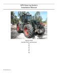
GPS Steering System
Installation Manual
Supported Vehicles
Challenger
Massey Ferguson
AGCO
MT-645C
MF-8650
DT-205B
MT-655C
MF-8660
DT-225B
MT-665C
MF-8670
DT-250B
MT-675C
MF-8680
DT-275B
All Autoguide2 Ready vehicles with Factory
CAN Steering Valve and Wheel Angle Sensor
PN: 602-0234-01-A
LEGAL DISCLAIMER
Note: Read and follow ALL instructions in this manual carefully before installing or operating the AutoSteer system.
Note: Take careful note of the information in the Safety Information section and throughout this manual.
The manufacturer disclaims any liability for damage or injury that results from failure to follow the instructions and warnings
set forth herein.
Please take special note of the following warnings:
1. There is NO obstacle avoidance system included in the manufacturer’s product. Therefore, users must always have an
operator on the equipment when the AutoSteer system is in use to look for any obstacles including people, animals, trees,
ditches, buildings, etc.
2. During installation of the AutoSteer system and during the Calibration and Tuning processes the vehicle steering system
can move the vehicle and turn the front wheels. Be sure that all people and obstacles are clear of the vehicle on all sides
before engine startup, calibration, tuning or use of the AutoSteer system.
3. Use of the AutoSteer system is NOT permitted while equipment is on roads or in public areas. Follow the instructions set
forth below for ensuring that the system is OFF before driving on roads or in public areas.
ii
GPS AutoSteer System
Special Requirements
Tools
This list consists of the tools required to complete the installation. The installer is assumed to have a complete set of common
installation tools.
10mm socket and ratchet
3/8" wrench
Multimeter (voltmeter)
13mm socket and ratchet
7/16" wrench
Ladder, 10 ft (3m)
16mm socket and ratchet
1/2" wrench
Wire cutters
17mm socket and ratchet
15/16” wrench
Tape measure 12 ft (3.7m) minimum
24mm socket and ratchet
24mm wrench
Cleaning rags
#1 Phillips screwdriver
Automotive grease
Cleaning brush
#2 Phillips screwdriver
Epoxy adhesive
Hardware Installation Manual
iii
Safety Information
Warning Alerts
The AutoSteer system installer and manufacturer disclaim any responsibility for damage or physical harm caused by failure to
adhere to the following safety requirements:
•
•
As the operator of the vehicle, you are responsible for its safe operation.
The AutoSteer system is not designed to replace the vehicle’s operator.
Note: Verify that all screws, bolts, nuts, hose connections and cable connections are tight after the final installation of the
AutoSteer system.
WARNING
To avoid electrical shock hazards, remove the Roof Module
from the vehicle before driving under low structures or low
electrical power lines.
WARNING
To prevent injury from falling, ensure you are in a stable
position on the vehicle when installing or removing the Roof
Rail and Roof Module. If the vehicle does not provide a safe
platform, use a ladder to safely access the vehicle roof while
installing or removing the Roof Rail and Roof Module.
WARNING
To prevent accidental death or injury from being run over by
the vehicle. Ensure all sides of the vehicle are clear of
people and obstacles before startup, calibration, tuning or
use of the AutoSteer system.
iv
GPS AutoSteer System
WARNING
To understand the potential hazards associated with the
operation of the AutoSteer system equipment read the
provided documentation before installing the AutoSteer
system on a vehicle.
WARNING
To prevent the accidental engagement of the AutoSteer
system and loss of vehicle control while driving on roads,
shut down the AutoSteer display (exit the program) and turn
off the AutoSteer main switch on the tractor console. Never
drive on roads or in public areas with the AutoSteer system
turned on.
Caution Alerts
The AutoSteer system installer and manufacturer disclaim any responsibility for damage or physical harm caused by failure to
adhere to the following safety requirements:
CAUTION
The Roof Module must be removed when transporting or
driving the vehicle at speeds above 30 mph (50 km/h). The
Roof Module can possibly detach due to wind loads at
higher speeds.
CAUTION
The AutoSteer system does not detect obstacles in the
vehicle’s path. The operator must observe the path being
driven in order to avoid obstacles.
Hardware Installation Manual
v
CAUTION
When engaged, the AutoSteer system controls only the
steering of the vehicle. The operator must control the speed
of the vehicle.
CAUTION
The AutoSteer system must be powered OFF when
installing or removing the Roof Module.
CAUTION
The Roof Module must always be firmly secured to the Roof
Rail using the hardware whenever the vehicle is in operation
to prevent the Roof Module from releasing from its bracket
and falling.
Vehicle Requirements
The tractor must be one of the AGCO models listed on this manual’s front cover and must be fully AutoGuide2 ready with the
factory Steering Valve, Wheel Angle Sensor, roof-top connector and wiring harness. Contact your AGCO dealer as necessary
to confirm the vehicle and Steering Valve are AutoSteer-2 Ready. Some vehicles require a firmware upgrade and a Steering
Valve or Wheel Angle Sensor calibration to fully enable the AutoSteer functionality. The firmware upgrade and calibration
must be performed by an authorized AGCO dealer using a factory service tool.
The steering system must be in good working order before installing AutoSteer. Drive the vehicle and confirm it steers straight
and is responsive. The electrical system and battery must be in good working order. The roof and cab electrical connectors
must not be damaged and in good working order. To improve the overall installation and cable routing, clean the cab and cab
roof before starting the installation. Check for loose or worn parts.
vi
GPS AutoSteer System
Important Information
This installation manual contains valuable information for servicing the AutoSteer system. After the installation is complete,
store this manual in a safe place for future reference.
Note: Verify that all screws, bolts, nuts and cable connections are tight after the AutoSteer system final installation.
Technical Support
Refer to your owner's manual for technical support information.
Contact Information
Refer to your owner's manual for contact information.
AutoGuide2 is a trademark of AGCO Corporation.
Copyright © 2010 All Rights Reserved.
Hardware Installation Manual
vii
viii
GPS AutoSteer System
Table of Contents
Chapter 1
Installation Overview ....................................................................................................... 1
Kit Overview . . . . . . . . . . . . . . . . . . . . . . . . . . . . . . . . . . . . . . . . . . . . . . . . . . . . . . . . . . . . . . . 2
Pre-Installation Vehicle Hardware and Software Verification . . . . . . . . . . . . . . . . . . . . . . . . . 3
Pre-Installation Vehicle Tests . . . . . . . . . . . . . . . . . . . . . . . . . . . . . . . . . . . . . . . . . . . . . . . . . . 4
Installation Procedure Outline . . . . . . . . . . . . . . . . . . . . . . . . . . . . . . . . . . . . . . . . . . . . . . . . . 5
Cable Diagram . . . . . . . . . . . . . . . . . . . . . . . . . . . . . . . . . . . . . . . . . . . . . . . . . . . . . . . . . . . . . 6
Chapter 2
Roof Module Installation.................................................................................................. 7
Safety Notes . . . . . . . . . . . . . . . . . . . . . . . . . . . . . . . . . . . . . . . . . . . . . . . . . . . . . . . . . . . . . . . . 7
Challenger MT-600C Installation Procedure . . . . . . . . . . . . . . . . . . . . . . . . . . . . . . . . . . . . . . . 9
Massey Ferguson MF-8600 and AGCO DT-200B Installation Procedure . . . . . . . . . . . . . . . 15
Chapter 3
Display Installation ......................................................................................................... 23
Chapter 4
Connecting System Cables............................................................................................ 25
Roof Module Connection. . . . . . . . . . . . . . . . . . . . . . . . . . . . . . . . . . . . . . . . . . . . . . . . . . . . . 25
Roof Module Serial Communication Connection . . . . . . . . . . . . . . . . . . . . . . . . . . . . . . . . . . 32
Power Supply Connection . . . . . . . . . . . . . . . . . . . . . . . . . . . . . . . . . . . . . . . . . . . . . . . . . . . . 36
Cab Power Connection . . . . . . . . . . . . . . . . . . . . . . . . . . . . . . . . . . . . . . . . . . . . . . . . . . . . 37
Battery Power Connection . . . . . . . . . . . . . . . . . . . . . . . . . . . . . . . . . . . . . . . . . . . . . . . . . . 38
Chapter 5
Post-Installation Procedures and Information ............................................................. 41
Create a New Vehicle . . . . . . . . . . . . . . . . . . . . . . . . . . . . . . . . . . . . . . . . . . . . . . . . . . . . . . . 41
Verify the Vehicle is Ready for AutoSteer . . . . . . . . . . . . . . . . . . . . . . . . . . . . . . . . . . . . . . . 42
Calibration and Tuning Notes . . . . . . . . . . . . . . . . . . . . . . . . . . . . . . . . . . . . . . . . . . . . . . . . . 43
Vehicle Specific Installation Calibration and Tuning Guidelines . . . . . . . . . . . . . . . . . . . . 43
Chapter 6
Final Hardware Installation Checklist ........................................................................... 45
Hardware Installation Manual
ix
x
GPS AutoSteer System
1
Installation Overview
This Installation Overview chapter contains part numbers, kit overview diagram, cabling diagram and the installation
procedure.
•
•
•
•
•
Kit Overview
Pre-Installation Vehicle Hardware and Software Verification
Pre-Installation Vehicle Tests
Installation Procedure Outline
Cable Diagram
This installation guide describes the installation of the AutoSteer system on several models of Challenger, Massey Ferguson
and AGCO series vehicles. The AutoSteer installation kit PN: 188-0025-01 supports the AGCO Autoguide2 models listed on
the front cover.
Hardware Installation Manual
1
Kit Overview
Kit Overview
The Installation Kit (PN 188-0025-01) contains the components shown in Figure 1-1.
Figure 1-1
AGCO MT-600C AutoGuide2 Kit Components (PN: 188-0025-01)
Table 1-1
Installation Kit Components
2
Item
Component
Part Number
1.
Cable Routing Hardware
200-0121-01
2.
Roof Module Bracket
200-0525-01
3.
Installation Manual
602-0234-01
4.
Display RAM Mount Assembly
207-0010-01
5.
AutoGuide2 Harness
201-0479-01
6.
Ethernet Cable
201-0497-01
9.
Roof Rail
200-0515-01
10.
Blanking Connectors
200-0520-01
GPS AutoSteer System
Pre-Installation Vehicle Hardware and Software Verification
Item
Component
Part Number
11.
Roof Module Brackets
200-0583-01
Pre-Installation Vehicle Hardware and Software
Verification
Before beginning the AutoSteer installation, you must verify your vehicle has the appropriate hardware and software installed.
1. Verify that the AutoGuide2 connector is present on the cab roof front left corner. See Figure 1-2.
Note: This connector is used for connecting your ParaDyme Roof Module for vehicle power and the CAN interface.
Figure 1-2
Accuguide2 Connector on Roof
AutoGuide2 Connector
2. Confirm the vehicle has the correct Steering Valve firmware installed and fully supports AutoGuide2.
Note: If you are uncertain about your firmware version, contact your AGCO dealer.
Hardware Installation Manual
3
Pre-Installation Vehicle Tests
Pre-Installation Vehicle Tests
The vehicle steering system must be in good working condition prior to AutoSteer System installation. Verify the existing
steering system is operating correctly by performing the tests listed below.
Note: The AutoSteer system test requires a relatively large area for vehicle movement. Ensure you have enough room to
perform the test before beginning.
1. Drive the vehicle in a low gear and slowly turn the steering wheel full left. The vehicle should steer to the left at a steadily
increasing rate until it is making a sharp left turn.
2. Drive the vehicle in a low gear and slowly turn the steering wheel full right. The vehicle should steer to the right at a
steadily increasing rate until it is making a sharp right turn.
Note: The change in steering speed and angle should also be proportionally opposite to what was noticed when
turning the vehicle to the left. The vehicle should react at the same speed and turn at the same angle when the steering
wheel is turned the same angle either left or right.
3. Drive the vehicle in a straight line on flat terrain in a low gear and release the steering wheel.
Note: The vehicle should continue to drive straight after releasing the wheel without drifting right or left.
4. Ask the vehicle driver or owner if they have experienced any vehicle steering problems. The operator should report no
steering problems.
Note: If the vehicle passes the four tests, proceed with the AutoSteer system installation.
Note: If the vehicle fails one or more of the tests, the steering system must be evaluated by an AGCO dealer and
repaired if necessary.
4
GPS AutoSteer System
Installation Procedure Outline
Installation Procedure Outline
Note: The system interconnect cable diagram in the Cable Diagram on page 6 section of this chapter shows the
AutoSteer system electrical connections and should be used as a reference during the installation process.
When installing and electric steering actuator such as OnTrac2, skip Step 2. and Step 6. and follow the supplementary
instructions provided with your electric steering unit.
1. Verify the components received match the shipping documentation.
2. Verify the vehicle has the proper factory software and hardware installed for AutoGuide2.
3. Install the Roof Rail and Roof Module
4. Install the Display mounting bracket.
5. Install the Display using the RAM Mount Arm.
6. Connect the roof CAN harness.
7. Connect the Ethernet cable. (when required)
8. Connect the power and Display cables.
Note: Instructions for connecting the Display electrical connections are found in the Display User Manual.
9. Ensure all connectors and cables are properly coupled secured with cable ties.
10. Power ON the AutoSteer system.
11. Calibrate the AutoSteer system.
12. Tune the AutoSteer system.
13. Verify the AutoSteer system has been properly installed and operates satisfactorily.
Note: An optional Wheel Angle Sensor is not offered for this installation. The AutoSteer system always uses the
factory provided front axle Wheel Angle Sensor.
Hardware Installation Manual
5
Cable Diagram
Cable Diagram
6
GPS AutoSteer System
2
Roof Module Installation
This Roof Module Installation chapter contains information in the following sections:
•
•
•
Safety Notes
Challenger MT-600C Installation Procedure
Massey Ferguson MF-8600 and AGCO DT-200B Installation Procedure
Safety Notes
•
•
•
•
The AutoSteer system must be powered OFF when installing or removing the Roof Module.
The Roof Module must be removed when transporting the vehicle at speeds above 30 mph/50 kph.
The Roof Module must always be firmly secured to the Roof Rail using the hardware provided whenever the vehicle is in
operation to prevent the Roof Module from releasing from its bracket and falling.
Ensure you are in a stable position on the vehicle platform when removing the Roof Module, to ensure you do not fall or
drop the Roof Module.
WARNING
To prevent injury from falling, ensure you are in a stable
position on the vehicle when installing or removing the Roof
Rail and Roof Module. If the vehicle does not provide a safe
platform, use a ladder to safely access the vehicle roof while
installing or removing the Roof Rail and Roof Module.
Hardware Installation Manual
7
Safety Notes
There are two styles of cab roof mounts depending on the tractor model. The Challenger MT-600C series has a roof style as
shown in Figure 2-1 with two light mounts and no hatches or covers. The Massey Ferguson MF-8600 series and AGCO
DT-200B series have the roof style shown in Figure 2-2 with a maintenance cover.
Figure 2-1
Challenger MT-600C Rooftop
Figure 2-2
Massey Ferguson MF-8600 and AGCO DT-200B Rooftops
8
GPS AutoSteer System
Challenger MT-600C Installation Procedure
Challenger MT-600C Installation Procedure
1. Locate the two beacon mounting plates on top of the cab. The left beacon mounting plate is shown in Figure 2-3.
Note: If the beacons are installed on the vehicle, the same kit will work. Follow the instructions provided except
ensure the beacons are reattached after bracket installation.
Figure 2-3
Mounting Screw Location
Beacon Mounting Location
Hardware Installation Manual
9
Challenger MT-600C Installation Procedure
2. Remove the three hex bolts holding the cap with a 10mm socket and ratchet.
3. Assemble both of the Roof Rail brackets as shown in Figure 2-4.
4. Attach an 8mm nut to the rear leveling screw.
5. Turn the leveling screw into the threaded hole at the bracket rear.
6. Attach another 8mm nut to the screw opposite side.
Figure 2-4
Assemble Roof Rail Bracket
Roof Rail Bracket
Top Lock Nut
Bottom Lock Nut
Leveling Screw
10
GPS AutoSteer System
Challenger MT-600C Installation Procedure
7. Attach the Roof Rail bracket to the roof using the new longer kit provided M6 x 25mm bolts with the Roof Rail mounting
holes facing the vehicle front. See Figure 2-5.
8. Tighten the bolts with a 10mm socket and ratchet.
Figure 2-5
Attach the Roof Rail Mounting Bracket (Left Side Shown)
Roof Rail Mounting Bracket
9. Repeat the above process and attach the other Roof Rail mounting bracket on the cab right side.
10. Adjust the rear bracket leveling screw so it holds the Roof Rail bracket parallel to the ground while compressing against
the roof slightly, as shown in Figure 2-6.
11. Tighten the two lock nuts with two 13mm wrenches.
Figure 2-6
Adjust Leveling Screw
Leveling Screw
Hardware Installation Manual
11
Challenger MT-600C Installation Procedure
12. Place the Roof Rail on top of the Roof Rail mounting brackets and center it over the cab.
Note: Ensure the Roof Rail Quick Release Pin is on the vehicle left side.
13. Confirm the Roof Rail is mounted perpendicular to the cab roof using the same bracket holes on the right and left brackets.
14. Attach the Roof Rail using the kit provided 5/8” x 1” bolts, washers and nuts. See Figure 2-7.
15. Tighten the bolts with a 15/16” wrench and 15/16” socket and ratchet.
Figure 2-7
Attach Roof Rail
Roof Rail
Mounting Bolts
12
GPS AutoSteer System
Challenger MT-600C Installation Procedure
16. Attach the three antennas to the proper Roof Module connections. See Figure 2-8.
Note: Hand tighten the connections. Do not over tighten.
Figure 2-8
Antennas Attached to Roof Module
RTK Radio Modem Antenna
Cell Modem Antenna
WiFi Antenna
17. Remove the Roof Rail locking pin. See Figure 2-9.
Figure 2-9
Removing the Locking Pin
Locking Pin
Hardware Installation Manual
13
Challenger MT-600C Installation Procedure
18. Place the Roof Module on the Roof Rail
19. Re-insert the locking pin to lock the Roof Module onto the vehicle. See Figure 2-10.
Note: The locking pin can be inserted from either side of the Roof Rail.
Figure 2-10 Locking Pin Inserted
Roof Module Locked
20. The Roof Module is now installed. See Figure 2-11.
Figure 2-11 Roof Module Installed
14
GPS AutoSteer System
Massey Ferguson MF-8600 and AGCO DT-200B Installation Procedure
Massey Ferguson MF-8600 and AGCO DT-200B Installation
Procedure
1. Locate the three hex screws on each side attaching the plastic maintenance cover on the cab roof right and left sides. See
Figure 2-12.
2. Remove the three screws on each side for securing the two mounting brackets.
Figure 2-12 Mounting Bracket Bolt Locations
Mounting Bolts
Note: The factory screws are threaded into metal inserts in the cab roof. If the threaded insert unscrews from the roof
when you remove the original screw, you must re-install and bond it with epoxy adhesive on the insert's external
threads before you can proceed with the installation. To re-install the threaded insert in the roof, temporarily thread an
M8 screw with an M8 jam nut into the insert then turn the screw so that the insert rotates and threads flush into the
roof. Release the jam nut while holding the screw head, then remove the screw from the insert. There is a kit provided
M8 nut.
Hardware Installation Manual
15
Massey Ferguson MF-8600 and AGCO DT-200B Installation Procedure
Note: To avoid possible damage, do not use conventional thread lockers such as Loctite on the plastic cab roof. Use
only an Epoxy adhesive or a product recommended by your AGCO dealer.
3. Install one bracket on each side aligning the bracket holes with the existing threads. See Figure 2-13.
Note: The right and left brackets are identical.
4. Secure each bracket with three kit provided longer hex screws and washers.
Note: Apply a small amount of grease to the screw threads before assembly to protect the threads.
Figure 2-13 Roof Bracket Mounted
Second Bracket Location
Roof Bracket Mounted
16
GPS AutoSteer System
Massey Ferguson MF-8600 and AGCO DT-200B Installation Procedure
5. Tighten the bracket bolts using a 13mm socket wrench. See Figure 2-14.
Note: Do not over-tighten the bolts.
Figure 2-14 Tightening the Bracket Bolts
Hardware Installation Manual
17
Massey Ferguson MF-8600 and AGCO DT-200B Installation Procedure
6. Install the Roof Rail over the rear bracket holes. See Figure 2-15.
Note: Ensure the Roof Rail is aligned perpendicular to the roof. The Roof Rail quick release pin should be on the cab
left side.
7. Center the Roof Rail over the roof using the hole number six for the left mounting bolt.
8. Secure the Roof Rail to the brackets on each cab side using the kit provided M16 hex bolt, two washers and locknut.
Figure 2-15 Roof Rail Mounted On Brackets
Mounting Bolts
18
GPS AutoSteer System
Massey Ferguson MF-8600 and AGCO DT-200B Installation Procedure
9. Attach the three antennas to the proper Roof Module connections. See Figure 2-16.
Note: Hand tighten the connections. Do not over tighten.
Figure 2-16 Antennas Attached to Roof Module
RTK Radio Modem Antenna
Cell Modem Antenna
WiFi Antenna
Figure 2-17 Remove Locking Pin
Locking Pin
Hardware Installation Manual
19
Massey Ferguson MF-8600 and AGCO DT-200B Installation Procedure
10. Place the Roof Module on the Roof Rail. See Figure 2-18.
Figure 2-18 Roof Module Mounted
11. Reinsert the Locking Pin into the Roof Rail. See Figure 2-19.
Note: The Roof Brackets and Roof Rail must be removed whenever the roof maintenance cover is opened for
servicing the air conditioner. Re-install the Roof Rail following the correct installation procedure whenever the
maintenance cover is removed for servicing the vehicle.
Figure 2-19 Reinsert Locking Pin
Locking Pin
20
GPS AutoSteer System
Massey Ferguson MF-8600 and AGCO DT-200B Installation Procedure
Note: The Locking Pin can be inserted from either Roof Rail side.
12. The Roof Module is now installed.
Hardware Installation Manual
21
Massey Ferguson MF-8600 and AGCO DT-200B Installation Procedure
22
GPS AutoSteer System
3
Display Installation
This Display Installation chapter contains information for mounting the system Display.
Note: This chapter provides instructions for installing the RAM mount ball in the cab. After the RAM mount is installed
the Display can be attached. Refer to your Display User Manual for installation instructions.
1. Locate the identify the cab right side bracket mounting bar. See Figure 3-1.
Figure 3-1
Identify the Bracket Mounting Bar
Display Bracket Mounting Bar
Hardware Installation Manual
23
Display Installation
2. Attach the RAM Mount Ball to the mounting bar with the two kit provided U-bolts and nuts.
3. Point the RAM Ball at an angle downward towards the seat. See Figure 3-2.
4. Tighten the bracket with a 1/2” wrench.
5. Install the four vinyl caps over the bolts.
Figure 3-2
Display Bracket Installed
U-Bolt
Vinyl Cap
Note: Refer to the Display user manual for the remaining Display specific installation instructions.
24
GPS AutoSteer System
4
Connecting System Cables
This Connecting System Cables chapter contains information in the following sections:
•
•
•
Roof Module Connection
Roof Module Serial Communication Connection
Power Supply Connection
• Cab Power Connection
• Battery Power Connection
Roof Module Connection
Note: Refer to the Cable Diagram on page 6 and your Display user manual for information on cable connections.
Note: You can skip the Ethernet connection instructions if your Display requires a serial connection.
Hardware Installation Manual
25
Roof Module Connection
1. Connect the Main Harness from the Roof Module to the existing cab roof connector. See Figure 4-2.
2. Orient the 12-pin connector so the word TOP on the cable connector is pointing upwards (towards the sky). See Figure 4-1.
3. Insert the cable connector into the Roof Module. Push the connector in until it clicks and locks in place.
Note: To remove the connector, grasp the connector to compress the two side latches and then pull away from the
Roof Module.
Figure 4-1
Connecting the Main Cable Harness to the Roof Module
Main Cable Harness Connection
26
GPS AutoSteer System
Roof Module Connection
4. Route the cable under the Roof Rail and secure with cable ties allowing sufficient length to make a wide loop. See
Figure 4-2.
Figure 4-2
Roof Module Main Harness Connection
Main Harness Connections
Hardware Installation Manual
27
Roof Module Connection
Note: You can skip the Ethernet connection instructions if your Display requires a serial connection. Proceed to the
Roof Module Serial Communication Connection section on page 32 if your installation requires a serial connection.
5. Connect the cable to the cab roof connector. See Figure 4-3.
6. Rotate the connector sleeve clockwise to engage and counterclockwise to disengage.
7. Store the original connector cap in the cab roof retaining bracket provided.
Note: Do not force the connector.
Figure 4-3
Cab Roof Connection
Cable Connector
28
GPS AutoSteer System
Roof Module Connection
8. Orient the Ethernet cable connector with the connector under the receiver so the cable connector contacts are pointing
towards the vehicle rear. See Figure 4-4.
Note: This orientation is usually towards your right side if you are standing on the vehicle left side and looking towards
the Roof Module.
9. Slide the cable connector into the receiver and rotate the plastic bayonet sleeve clockwise to lock the connector. See
Figure 4-4.
Figure 4-4
Roof Module Ethernet Connection
Ethernet Connection
Hardware Installation Manual
29
Roof Module Connection
10. Route the Ethernet Cable along the back of the Roof Rail and secure with cable ties. See Figure 4-5.
Note: Do not attach the cable ties around the top or bottom parts of the Roof Rail bracket so the Roof Module can
freely slide along the Roof Rail when it is installed and removed.
Figure 4-5
Route Cable to Right of Cab
Secure Ethernet Cable to Roof Rail Rear Side
11. Route the Ethernet cable down the cab rear and secure it with cable ties to the rear light and the two cab post brackets. See
Figure 4-6.
Figure 4-6
Secure Cable to Rear Handle Bar
Secure Harness
30
GPS AutoSteer System
Roof Module Connection
12. Route the Ethernet cable into the cab through the wire access port.
13. Secure the Ethernet cable with cable ties both inside and outside the cab.
14. If necessary, cut a slot in the rubber grommet. Replace the wire access rubber grommet allowing the Ethernet Cable to pass
into the cab. See Figure 4-7.
15. Close the rear window.
Figure 4-7
Route Harness into Cab
Cables into Cab
Hardware Installation Manual
31
Roof Module Serial Communication Connection
Roof Module Serial Communication Connection
Note: You may skip the serial connection instructions if your display uses a Roof Module Ethernet connection.
1. Identify the plastic cover near the driver seat right side floor.
2. Release the two latches and remove the cover by pulling it forward.
Figure 4-8
Access Cover
Latches
32
GPS AutoSteer System
Roof Module Serial Communication Connection
3. Remove the plastic cover just to the driver seat right to reach the vehicle serial connector. See Figure 4-9.
Figure 4-9
Serial Connector Access Cover Removed
Hardware Installation Manual
33
Roof Module Serial Communication Connection
4. Locate the DE9 serial connector. See Figure 4-10.
Note: This DE9 connector is the connection point for your Display harness. Use this serial connection when the Display
user manual recommends a serial Roof Module connection.
Figure 4-10 Serial DE9 Connector
34
GPS AutoSteer System
Roof Module Serial Communication Connection
5. Connect the serial connector on your Display harness to the vehicle serial connector inside the cab. See Figure 4-11.
Note: Refer to the Cable Diagram on page 6 for additional electrical connection information. The serial connector
should remain under the plastic cover after the installation is completed.
Figure 4-11 Serial Connection
Serial Cable and Connector
Hardware Installation Manual
35
Power Supply Connection
Power Supply Connection
The following sub-sections describe basic instructions for connecting the AutoSteer system to available vehicle power
sources:
•
•
Cab Power Connection
Battery Power Connection
Note: Refer to your Display user manual for electrical connection information before attempting to connect the AutoSteer
system to vehicle power. If your Display manual requires a cab power connection see the Cab Power Connection section,
if your Display manual requires a direct battery connection see the Battery Power Connection section.
There are two issues that must be addressed when connecting to 12V vehicle power:
•
•
Display Connection
AutoSteer System Connection
The Display must be connected to 12V vehicle power according to the wiring diagram provided with your Display. The
AutoSteer system Main Cable Harness must be connected to a 3-pin 12V power connector. Your Display user manual provides
a wiring diagram for connecting the AutoSteer system to 12V Power.
Your Display user manual may specify using a cab 12V power outlet or may require a direct connection to the vehicle battery.
Your Display wiring diagram specifies the recommended vehicle 12V power source. Whether your Display harness connects
to the vehicle battery or to the 12V power outlet inside the cab, it is shipped with the appropriate harness for your installation.
Note: In this installation the Roof Module is connected to the vehicle 12V power through the roof connector and does not
require a separate power connection.
36
GPS AutoSteer System
Cab Power Connection
Cab Power Connection
1. Locate the cab console right-side 12V power outlet. See Figure 4-12.
2. Use this 12V accessory power connector if the display manual specifies connecting to power inside the cab.
Figure 4-12 Cab 12V Power Outlet
Cab Power Connection
Hardware Installation Manual
37
Battery Power Connection
Battery Power Connection
1. Locate the vehicle battery. See Figure 4-13.
2. Connect to the vehicle battery if the display manual specifies a direct battery connection.
Figure 4-13 Vehicle Battery Location
Battery Location
Battery Box Lock
3. Using the ignition key, unlock the battery box and open the lid. The batteries are shown in Figure 4-14.
Figure 4-14 Vehicle Batteries
38
GPS AutoSteer System
Battery Power Connection
Note: A battery cable is provided with the AutoSteer system when a direct battery connection is required.
Hardware Installation Manual
39
Battery Power Connection
40
GPS AutoSteer System
5
Post-Installation Procedures and
Information
This Installation Completion Procedures chapter contains information on procedures and processes that should be
performed after the installation process is complete. The information for this chapter is contained in the following sections:
•
•
•
Create a New Vehicle
Verify the Vehicle is Ready for AutoSteer
Calibration and Tuning Notes
• Vehicle Specific Installation Calibration and Tuning Guidelines
Create a New Vehicle
After the entire system has been installed, including the Display and Roof Module, the operator must create a new vehicle
profile using the AutoSteer system. The vehicle profile configures the hardware and enables the display to communicate with
the various sensors and vehicle components.
Follow the procedure below to create a new vehicle:
Hardware Installation Manual
41
Verify the Vehicle is Ready for AutoSteer
1. Ensure the vehicle is still in Park and/or the park brake is set to prevent the vehicle from moving.
2. Ensure the vehicle is off. Do not start the vehicle yet.
3. Power up the AutoSteer system
4. Follow the instructions provided in the Display User Manual to create a new vehicle.
Verify the Vehicle is Ready for AutoSteer
1. A three-position console switch turns the Roof Module power on and off and the Steering Valve on and off. See Figure 5-1.
Figure 5-1
Console Switch
Console Switch
2. The Console Switch position functions are as follows:
a.
The OFF position shuts down power to the GPS Roof Module and Steering Valve and is the recommended position
when you are not using your ParaDyme system.
b.
The middle antenna position turns on only the GPS Roof Module power.
c.
The steering wheel position turns on power to both the GPS Roof Module and Steering Valve and is the
recommended position for normal AutoSteer operations.
3. Refer to your vehicle owners manual for recommended switch operation.
42
GPS AutoSteer System
Calibration and Tuning Notes
Note: Always shut down your ParaDyme system and put the switch in the OFF position when driving on public roads
and when the tractor is not being used. Failure to put the switch in the OFF position keeps the Roof Module powered
up and discharges the battery over an extended time period. Simply turning off the AutoSteer display does not turn off
the Roof Module.
Note: Always turn off your AutoSteer display and Roof Module before starting the engine. Only turn on your display
and roof module after the engine is running.
4. Verify the vehicle is responding to AutoSteer commands by going to the Steering Components screen and then the Valve
screen where you can manually command the wheels to turn right and left.
Note: Refer to your ParaDyme User manual for more details.
Note: If the tractor does not respond to the AutoSteer system and the front wheel do not turn, check all your cable
connections then confirm that the tractor is fully factory configured for AutoGuide2 with the correct software and
hardware. Contact your AGCO dealer for AutoGuide2 support and he has the appropriate tools to update the vehicle
software and calibrate the factory system if necessary.
Calibration and Tuning Notes
Vehicle Specific Installation Calibration and Tuning Guidelines
Note: For optimal AutoSteer performance, the AutoSteer system must be fully calibrated and then tuned.
Note: Select the appropriate Challenger MT vehicle model when setting up your vehicle on the AutoSteer system display.
Hardware Installation Manual
43
Vehicle Specific Installation Calibration and Tuning Guidelines
44
GPS AutoSteer System
6
Final Hardware Installation Checklist
This Final Hardware Installation Checklist chapter contains the verifications steps necessary after AutoSteer system
installation.
Note: The Final Hardware Installation Checklist is on the back of this page. Fill in the checklist after the installation. You
should keep a copy of this checklist for future reference when servicing the AutoSteer system.
Machine Model: _________________________________ Year: _________ Serial #: _________________________
Customer Name: _______________________________________________________________________________
Location/Address: ______________________________________________________________________________
AutoSteer Installation Kit Part Number: ______________________________________________________________
NOTES
____________________________________________________________________________________________________
____________________________________________________________________________________________________
____________________________________________________________________________________________________
____________________________________________________________________________________________________
____________________________________________________________________________________________________
____________________________________________________________________________________________________
Name of Installer: __________________________________________
Date: ________________
Hardware Installation Manual
45
Final Hardware Installation Checklist
System Installation Checklist
1. Monitor Bracket Installed and all fasteners are tight.
2. Roof Rail and Roof Module are installed and all fasteners are tight.
3. All cable ends are connected.
4. All cables are secured with cable ties.
5. Vehicle is fully configured for AutoGuide2 with correct firmware version.
AutoSteer Performance Checklist
1. Complete AutoSteer system calibration.
2. Complete AutoSteer system tuning.
3. Verify that line acquisition is good.
4. On-line steering is good.
5. Manual override (kick-out) is working.
6. Steering speed from lock-to-lock is satisfactory.
46
GPS AutoSteer System
Value___________Sec.