1
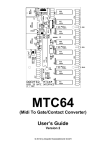
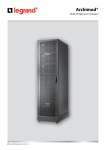
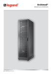
DOEPFER MUSIKELEKTRONIK GMBH
MTV16
Midi-to-Voltage Interface with
16 Analog Voltage Outputs 0…+5V
Installation and User's Guide
V1.0
© 2009 by Doepfer Musikelektronik
Table of contents
Table of contents ...................................................................................................................................... 2
Introduction............................................................................................................................................... 3
Electrical safety / EMC compatibility......................................................................................................... 4
Warranty notes ......................................................................................................................................... 4
Connections.............................................................................................................................................. 5
Power Supply (BU3) ............................................................................................................................. 5
Midi In (BU1) ......................................................................................................................................... 5
Midi Out (BU2) ...................................................................................................................................... 5
Control LED (D4) .................................................................................................................................. 5
Analog Voltage Outputs (JP1 / JP2) ..................................................................................................... 5
Overview: MTV16 Connections and Controls........................................................................................... 6
Detailed function of the 8 jumpers of JP5 ............................................................................................. 7
Mounting................................................................................................................................................... 8
Extent of delivery ...................................................................................................................................... 8
Introduction
•
•
•
•
•
•
•
•
•
•
•
•
•
•
•
•
MTV16 is an interface that converts midi control changes messages (sometimes called
simply "midi controllers") into 16 analog voltages
Output voltage range: 0…+5V (0V corresponds to midi data 0, +5V corresponds to midi data
127)
Resolution of the voltages: 128 steps or 7 bit (based on the 7 bit midi data)
the voltages are available as two pin heades with 10 pins each, each pin header has
available 8 voltages and GND on two pins
Two female connectors with 10 pin ribbon cables can be used to wire the outputs to obtain
removable connections.
The voltages are controlled by 16 subsequent midi control changes messages on the same
midi channel.
The midi channel that is used to control the 16 outputs is adjusted by means of four jumpers.
The control change number of the first output can be set to 0, 16, 32, 48, 64, 80, 96 or 112
by means of three jumpers.
MTV16 is equipped with Midi In and Midi Thru. The incoming Midi messages are forwarded
to the Thru output without any changes. In this way several MTV16 can be linked together.
MTV16 is available only as an assembled and tested pc board.
The pc board measures are about 78 mm (length) x 67 mm (width) x 25 mm (height).
Several mounting holes with 3 mm diameter are available for mounting the pc board to a
suitable base e.g. with distance sleeves or spacers and screws.
We do not offer a suitable housing as this would have to be completely different for various
applications.
An external power supply (7-12VDC@min. 100mA) is used. Within Europe the wall outlet
power supply adapter for 230V mains voltage and European type mains plug is included with
the MTV16. In other countries the power supply has to be purchased by the user in his
country. If there is a Doepfer representative in your country please ask the representative if
the power supply is included in your country.
connectors for power supply, midi in and midi out are available as sockets on the pc board
Midi cables and cables/wire for the analog voltages are not included but can be ordered
together with the MTV16 (additional charges)
Installation of the MTV16 requires electrical/electronical knowledge by the user. Please leave
the installation of MTV16 to an expert if you are not familiar with electronics. We take back only
MTV16 modules in the original state, i.e. without solder residues, without scratches and so on.
Please pay attention to the warranty notes on page 4. Ignoring these notes causes warranty
loss and the right to return the goods.
Installation and User's Guide
MTV16
Page 3
Electrical safety / EMC compatibility
MTV16 is a so-called OEM product (OEM original equipment manufacturer) that cannot be
used independently but has to be combined with additional electrical or electronical equipment
to become a working device. The manufacturer of MTV16 does not know the final assembly of
the complete device in which the MTV16 is used as a part of the complete device. The final
responsibility with regard to electrical safety and electromagnetic compatibility is up to the
user who is assembling the complete device.
Please pay attention to the following items:
The power supply used in combination with the MTV16 has to be a closed type (in Germany a
power supply with VDE approval is required). Normally an AC adapter with plastic case is used.
It is not allowed to use open power supplies with open mains voltage access (e.g. via mains
lead, pcb tracks, electronic parts).
On the MTV16 board preventing measures against electromagnetic radiation are met (e.g.
RF filters at the power supply input). But it is impossible to estimate to what extend the
components added by the user affect the EMC properties of the complete assembly.
Therefore the complete device has to be shielded against electromagnetic radiation
(incoming and outgoing). These demands are normally met by a closed metal case that covers
the complete assembly. The metal case should be connected to GND of the MTV16.
Warranty notes
• The 16 control voltages are outputs and should connected only to inputs of other devices!
• Only high impedance inputs ( > 10kOhm) should be connected to the MTV16 outputs. The
circuits connected to the MTV16 outputs have to be free of any voltage, i.e. the inputs are not
allowed to have any active voltage level (e.g. GND, +5V).
• But the MTV16 outputs have a limited short circuit protection (100 Ohm serial resistors).
Connection an output by mistake to GND or any voltage between GND and +5V will not
destroy the MTV16. Shortening two MTV16 outputs will also not destroy anything.
• Applying any negative voltage or a voltage beyond +5V to one of the analog outputs will
destroy the MTV16.
• Do not apply any voltage to the pin headers with jumpers that are used to adjust the MTV16
parameters (e.g. Midi channel, control change number) but use only jumpers!
• We recommend not to solder directly to any of the pin headers but use female connectors to
make the connections between the MTV16 and your application. MTV16 includes two 10 pin
ribbon cables (about 30 cm each) for this purpose.
• Carry out all connections in the off-state of the MTV16 (i.e. without power supply) !
• The MTV16 electronics is an electrostatic sensitive device. Avoid any electrostatic charges !
• Avoid short cuts !
• Ignoring any of these items will cause warranty loss !
• Return of the MTV16 within the 2 weeks return time limit (valid only in Germany) is only
possible if all these items have been met. Return of used cable sets is not possible.
Page 4
MTV16
Installation and User's Guide
Connections
Power Supply (BU3)
The MTV16 does not have a built-in power supply. Instead it uses a plug-in type external power
supply (AC adapter). One reason for this feature is electrical safety. Keeping danger voltages
(main) out of the MTV16 increases the electrical safety. Therefore an external power supply of
high quality and safety should be used. If the unit is used in Germany the external power supply
has to be VDE approved. Another reason for the external power supply is the fact that line
voltages and plug types vary considerably from country to country. Using a plug-in external
supply the MTV16 can be used any where with a locally purchased power supply, thus keeping
the retail price down.
The power supply must be able to deliver 7-12 VDC unstabilized voltage, as well as a minimum
current of 100mA. The MTV16 is switched ON by plugging the AC adapter into a wall outlet and
connecting it to the appropriate jack on the MTV16 board. There is no separate ON/OFF switch.
If the polarity of the power supply is incorrect, the MTV16 will not function. However, there is no
danger of damage to the circuitry since it is protected by a diode. The correct polarity is: outside
ring = GND, inside lead = +7...12V. The power supply is not included with the MTV16 and has
to be purchased separately (exception: for deliveries within Germany a 230V power supply with
European type mains plug is included).
Midi In (BU1)
The Midi In of the MTV16 is connected to Midi Out of the device that generates the Midi control
change messages that are used to control the MTV16 outputs (e.g. Midi sequencer). The
incoming Midi data are used to control the outputs of the MTV16 provided that the Midi data
correspond to the jumper settings of the MTV16 (channel, control change numbers). If several
MTV16 are controlled from the same device the MTV16 can be daisy-chained via Midi-Thru Æ
Midi In. The Midi input of MTV16 is not suitable for large amounts of Midi data (e.g. long SysEx
strings or extensive Midi messages coming from an computer sequencer) as the Midi in buffer is
only 48 bytes. In case of large amounts of incoming Midi messages data loss or delay may
occur.
Midi Out (BU2)
MTV16 transmits the incoming Midi data unchanged to the Midi Out socket. This socket can be
connected to the Midi input of another Midi device that has to be controlled with the same Midi
data as the MTV16 (e.g. several daisy-chained MTV16). Otherwise this socket remains
unconnected.
Control LED (D4)
The LED is used to display any Midi In/Thru activity. After power on the LED is permanently on.
As soon as a relevant Midi out event occurs the LED turns off for a short time thus indicating
Midi activity.
Attention: Only Midi messages that are used to control the outputs of the MTV16 are displayed
by the LED. Other Midi messages are ignored (but they are forwarded to the Midi out socket).
Analog Voltage Outputs (JP1 / JP2)
JP1: output voltages 1 ... 8
JP2: output voltages 9 ... 16
Installation and User's Guide
MTV16
Page 5
Overview: MTV16 Connections and Controls
BU3
power supply
7-12V/100mA DC
JP1
pin header area
voltage outputs
1 …8
BU1
Midi in
JP2
pin header area
voltage outputs
9 ... 16
BU2
Midi out
1
2
3
4
5
6
7
8
D4
control LED
JP5
jpin header area to select
Midi channel and control
change number by means of
jumpers
JP4 and IC6
pin header JP4 and
memory chip IC6 are
without function so far
(IC6 is not assembled)
1
2
9
10
3
4
11
12
5
6
13
14
7
8
15
16
GND GND
GND GND
Pin Out JP1
(analog outputs 1 …8)
Pin Out JP2
(analog outputs 9 …16)
If the ribbon cables with double row female connectors are used the sequence of the upper
eight wires of the ribbon cables is the same as the outputs (i.e. 1 …8 or 9 …16).
Page 6
MTV16
Installation and User's Guide
JP5
JP5 is a 16 pin double row pin header that is used to set the Midi channel and the Midi Control
Change Number that is assigned to the first analog voltage output by means of jumpers.
The numbering is from top to bottom (please refer to sketch on the previous page).
The following table shows the relation between the jumpers 1 ... 4 of JP5 and the resulting Midi
channel:
Jumper
1
2
3
4
Midi
channel
1
2
3
4
5
6
7
8
9
10
11
12
13
14
15
16
= installed jumper
The following table shows the relation between the jumpers 5 ... 7 of JP5 and the resulting
Control Change Number (jumper 8 is unused):
5
Jumper
6
7
1
2
3
4
5
6
7
8
8
X
X
X
X
X
X
X
X
Function
Control Chance Number for the first output
0
16
32
48
64
80
96
112
= installed jumper
The pin header JP4 and the memory circuit IC6 (24C16) have no function so far. They may be
used for future features. IC6 is not assembled.
Installation and User's Guide
MTV16
Page 7
Mounting
Before MTV16 is put into operation the board should be fixed on a suitable support and built into
a metal case (refer to EMC notes on page 4). The metal case should be connected to GND of
MTV16. We recommend to use the GND terminal of the power supply socket for this
connection. The MTV16 will work without housing too but in this case the assembly may exceed
the EMC radiation limits in your country.
The board measures about 78 x 67 x 25 mm. Four mounting holes with 3 mm diameter are
available for mounting the board on a bottom plate e.g. with distance sleeves or spacers (> 5
mm in length) and suitable screws. Pay attention that no short circuits are made – neither on the
top of the board (electronic parts) nor on the bottom (solder points or pcb tracks). In case of
doubt use isolating plastic parts (e.g. plastic screws, nuts and washers) for mounting.
Extent of delivery
The MTV16 delivery contains the following parts:
•
•
•
•
MTV16 board, assembled and tested
Two 10 pin ribbon cables with double row female connectors, about 30 cm each (for wiring
of the 16 analog voltages)
This user's guide
Power Supply (230V mains voltage, European type mains plug, output voltage range
7...12V, current min. 100 mA) included only for shipments within Germany, for shipments
outside Germany please contact your local representative or dealer
Doepfer
Musikelektronik
www.doepfer.com
© 2010 by Doepfer Musikelektronik
Page 8
MTV16
Installation and User's Guide