1
Bedienungsanleitung
Operating instructions
R
Dialoggerät
Dialogue module
F1
F2
ENGLISH
DEUTSCH
ecomat tdm R 360
CR1001
CR1003
CR1021
Inhalt
1. Sicherheitshinweise . . . . . . . . . . . . . . . . . . . . . . . . Seite 3
3. Bedien- und Anzeigeelemente . . . . . . . . . . . . . . . . Seite 4
4. Vorbereitungen für den Betrieb . . . . . . . . . . . . . . . Seite 4
Erste Schritte . . . . . . . . . . . . . . . . . . . . . . . . . . . . . Seite 4
Programmieren . . . . . . . . . . . . . . . . . . . . . . . . . . . . Seite 5
5. Beschriften der Funktionstasten . . . . . . . . . . . . . . . Seite 5
6. Montage . . . . . . . . . . . . . . . . . . . . . . . . . . . . . . . Seite 5
7. Elektrischer Anschluß . . . . . . . . . . . . . . . . . . . . . . . Seite 6
8. Betrieb . . . . . . . . . . . . . . . . . . . . . . . . . . . . . . . . . Seite 6
9. Technische Daten . . . . . . . . . . . . . . . . . . . . . . . . . Seite 7
10. Anschlußbelegung . . . . . . . . . . . . . . . . . . . . . . . . . Seite 8
11. Maßzeichnungen . . . . . . . . . . . . . . . . . . . . . . . . . . Seite 8
12. Maße des Beschriftungsstreifens . . . . . . . . . . . . . . . Seite 8
Deutsch
2. Bestimmungsgemäße Verwendung . . . . . . . . . . . . . Seite 3
1.
2.
3.
4.
5.
6.
7.
8.
9.
10.
11.
12.
2
Safety instructions . . . . . . . . . . . . . . . . . . . . . . . . page 10
Function and features . . . . . . . . . . . . . . . . . . . . . page 10
Controls and visual indication . . . . . . . . . . . . . . . page 11
Preparations for the operation . . . . . . . . . . . . . . . page 11
First steps . . . . . . . . . . . . . . . . . . . . . . . . . . . . . . page 11
Programming . . . . . . . . . . . . . . . . . . . . . . . . . . . . page 12
Labelling the function keys . . . . . . . . . . . . . . . . . page 12
Mounting . . . . . . . . . . . . . . . . . . . . . . . . . . . . . . page 12
Electrical connection . . . . . . . . . . . . . . . . . . . . . . page 13
Operation . . . . . . . . . . . . . . . . . . . . . . . . . . . . . . page 13
Technical data . . . . . . . . . . . . . . . . . . . . . . . . . . . page 14
Wiring . . . . . . . . . . . . . . . . . . . . . . . . . . . . . . . . . page 15
Scale drawing . . . . . . . . . . . . . . . . . . . . . . . . . . . page 15
Dimensions of the label strip . . . . . . . . . . . . . . . . . page 15
English
Contents
1. Sicherheitshinweise
• Befolgen Sie die Angaben der Dokumentation. Nichtbeachten der Hinweise,
Verwendung außerhalb der nachstehend genannten bestimmungsgemäßen
Verwendung, falsche Installation oder Handhabung können Beeinträchtigungen der Sicherheit von Menschen und Anlagen zur Folge haben.
• Das Gerät darf nur von einer Elektrofachkraft eingebaut, angeschlossen und in
Betrieb gesetzt werden.
• Schalten Sie das Gerät extern spannungsfrei bevor Sie irgendwelche Arbeiten
an ihm vornehmen.
• Bei Fehlfunktion des Geräts oder bei Unklarheiten setzen Sie sich bitte mit dem
Hersteller in Verbindung. Eingriffe in das Gerät können schwerwiegende Beeinträchtigungen der Sicherheit von Menschen und Anlagen zur Folge haben. Sie
sind nicht zulässig und führen zu Haftungs- und Gewährleistungsauschluß.
Weiterführende Dokumentation zu Programmierung und Betrieb des
Dialoggeräts erhalten Sie im
Handbuch ecomat tdm R 360
Das tdm R 360 ist ein programmierbares Überwachungs- und Bedienmodul für SPSgesteuerte Anlagen. Es wurde speziell konzipiert für den Mobilbereich.
• Das Gerät kommuniziert über CAN-Bus mit dem Steuerungssystem ecomat R 360,
• zeigt dem Bedienpersonal Betriebszustände, Betriebs- und Meßdaten aller Bereiche
des Fahrzeugs / der Anlage,
• zeigt Meldungen des Fahrzeugs / der Anlage an,
• und erlaubt dem Bedienpersonal Eingriffe in die Steuerung des Fahrzeugs / der
Anlage (Eingabe von Sollwerten, Auslösen von Aktionen).
• Das tdm R 360 arbeitet auf der Grundlage einer frei progammierbaren Software.
Sie wird per PC erstellt und in das Gerät geladen.
Es lassen sich mehrstufige Bedien- und Anzeigemenüs erstellen, die komplexe und
flexible Anzeige und Bedienvorgänge ermöglichen.
Zusätzlich können einfache Kommunikations- und Anzeigeabläufe programmiert
und vom tdm R 360 abgearbeitet werden.
Der Artikel CR1003 verfügt zusätzlich über eine Echtzeituhr und über Protokoll- und
Statistikfunktionen. Damit lassen sich Betriebsdaten erfassen, auswerten und anzeigen.
3
DEUTSCH
2. Bestimmungsgemäße Verwendung
3. Bedien- und Anzeigeelemente
1
F1
F2
2
1
Display
grafikfähig, hinterleuchtet; Helligkeit und Kontrast einstellbar
2
LEDs (frei belegbar)
Funktionstasten
frei belegbar für Menüfunktionen, in den Grundfunktionen mit folgender Belegung:
= Menü beenden (Escape);
= Menü öffnen / Eingaben bestätigen (Enter)
/
= Cursortasten auf / ab,
/ = Cursortasten nach links / nach rechts: Auswählen von
Menüs oder Menüpunkten, Auswahl von Parametern, Verändern von Parameterwerten
4. Vorbereitungen für den Betrieb
Erste Schritte
Im Auslieferungszustand enthält das tdm R 360 ein Programm für Diagnose, Kommunikations- und Display-Einstellung.
• Bei Einschalten der Betriebsspannung (s. Kapitel “Elektrischer Anschluß”) meldet
sich das Gerät mit einer Initialisierungsgrafik und führt einen kurzen Selbsttest
durch.
• Anschließend können Sie mit dem Menü “CAN-Setup” die CAN-Schnittstelle konfigurieren (Default-Identifier: Sendekanal = 220; Empfangskanal = 221). Sie können diese Einstellungen allerdings komfortabler durch die Software vornehmen.
• Einstellen von Helligkeit und Kontrast des Displays:
- Drücken Sie die -Taste und halten Sie sie fest,
- und stellen Sie mit den Tasten / die Helligkeit ein, mit den Tasten / den
Kontrast. Halten Sie währenddessen die -Taste gedrückt.
4
Programmieren
1. Erstellen Sie das Arbeitsprogramm des tdm R 360 mit Hilfe des Editors ecolog
tdm R 360 (Bestell-Nr. CP9005). Es enthält neben den Bedien- und Anzeigemenüs
auch die Daten zur Konfiguration der CAN-Schnittstelle.
2. Entfernen Sie den Spanndeckel des tdm R 360 und verbinden Sie es über die serielle
Schnittstelle (RS232) oder über die CAN-Schnittstelle mit dem PC. Das Verbindungskabel ist als Zubehör erhältlich (Best.-Nr. EC2020).
3. Laden Sie das Arbeitsprogramm in den Speicher des tdm R 360 (mit Hilfe des entsprechenden Editor-Menüs).
Falls notwendig kann zusätzlich das Betriebssystem (TOS) über den Editor geladen
werden. Es wird zusammen mit dem Editor geliefert.
TOS- und Programm-Updates können jederzeit neu geladen werden.
Falls Probleme bei der Datenübertragung auftauchen, gehen Sie folgendermaßen vor:
- Konfigurieren Sie per Editor die serielle Schnittstelle auf: 9600 Baud - 8 Datenbits - 2 Stopbits no parity.
- Schalten Sie die Spannungsversorgung des tdm R 360 ab.
- Drücken Sie 4 beliebige Tasten, halten Sie sie fest und schalten Sie die Spannungsversorgung wieder
ein.
Das Gerät meldet sich mit der Anzeige “TERMINAL READY FOR UPLOAD” und Sie können die Software
übertragen.
5. Beschriften der Funktionstasten
1. Erstellen Sie einen Papierstreifen (Maße siehe Seite 8) und beschriften Sie ihn
den Maßen entsprechend.
2. Kleben Sie ihn an den Enden auf den mitgelieferten Plastikstreifen.
3. Ziehen Sie ihn so zwischen Tastatur und Frontfolie.
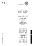
6. Montage
1
2
3
4
5
DEUTSCH
1. Erstellen Sie einen SchalttafelAusschnitt (187 x 101 mm),
entgraten und entfetten Sie ihn.
2. Kleben Sie die Dichtung (2) vorn auf
die Schalttafel (3).
3. Lösen Sie die Flügelschrauben (5)
und entfernen Sie den Spanndeckel
(4) des tdm R 360.
4. Setzen Sie das Gerät (1) in die
Schalttafel ein.
5.Setzen Sie den Spanndeckel (4) auf.
Ziehen Sie abwechselnd die beiden
Flügelschrauben (5) fest. Das Display
ist dann von vorn staubdicht und
strahlwasserfest gemäß IP 65.
5
7. Elektrischer Anschluß
Schalten Sie die Anlage spannungsfrei und schließen Sie das Gerät über die Steckverbindungen an. Anschlußbelegung s. Seite 8.
Schließen Sie die AMP-Fahne mit einem 6,3mm-Flachstecker an Masse an, damit die
EMV-Bedingungen eingehalten werden.
8. Betrieb
Funktionalität und Bedienung des tdm R 360 hängen ab von der Art der überwachten Anlage, von der Steuerung und vom Arbeitsprogramm, das für das tdm R 360
erstellt wurde.
Davon abgesehen bietet es folgende Grundfunktionen:
• Visualisierung
Das tdm R 360 bildet Betriebszustände ab (Betriebsdaten, Sollwerte, Istwerte usw.).
Dazu werden bestimmte Gruppen von Daten in “Bildern” zusammengefaßt und
mittels Text und Grafik angezeigt. Diese Bilder enthalten
- Texte (fest und dynamisch)
- feste und dynamische Grafiken: Pictogramme, Diagramme (Werte-Darstellung),
x-/y-Diagramme (Positions-Darstellung).
Die Bilder werden zyklisch angezeigt (je nach Programm-Vorgabe), können aber
auch manuell abgerufen werden (“Blättern” in Bildern).
• Meldung
Das tdm R 360 zeigt Betriebszustände, Betriebsdaten, Warnmeldungen, Alarmmeldungen u. ä. bei Eintritt des Melde-Ereignisses durch vordefinierte Texte an.
Meldungen erscheinen an oberster Stelle des Verarbeitungsstapels; d. h. sie überlagern das aktuelle Bild. Sie können so angelegt werden, daß das Bedienpersonal
sie durch Tastendruck quittieren muß.
Auch Meldungen werden im Speicher abgelegt und können manuell abgerufen
werden.
• Bedienmenü
Das tdm R 360 bietet die Möglichkeit, Daten in die Steuerung einzugeben (Sollwerte, Aktionen u. ä.). Dazu werden Bedienmenüs per Editor erstellt und im tdm
R 360 implementiert. Das Bedienpersonal
- wählt ein Menü aus der Liste der vorhandenen Menüs aus,
- öffnet das Menü
- wählt den zu verändernden Wert aus,
- öffnet den Editiermodus für diesen Wert
- verändert den Wert
- bestätigt die Veränderung
- sendet den neuen Wert zur Steuerung.
6
9. Technische Daten
Anzeige
Display
Hintergrundbeleuchtung
Helligkeit / Kontrast
Darstellungsarten
LCD-Supertwist, grafikfähig, 240 x 64 Punkte, 127 x 34 mm
LED (Lebensdauer 100 000 h)
einstellbar in 8 / 16 Stufen; temperaturkompensiert
2, 4 oder 8 Zeilen, Grafik und Text (mischbar)
10 / 20 / 40 Zeichen pro Zeile (bei 2 / 4 / 8 Zeilen)
Zeichenhöhe [mm]: 14 / 7 / 4 (bei 2 / 4 / 8 Zeilen)
IBM-Set 2, andere Zeichen möglich
Mechanische Daten
Gehäuse
Abmessungen
Einbauöffnung
Frontplatte
Tasten
Tastenkappe
[mm]
[mm]
Schutzart
Betriebstemperatur
Lagertemperatur
Vibration
Schock
Gewicht
[Kg]
Elektrische Daten
Betriebsspannung
[V]
Stromaufnahme
[°C]
[°C]
[mA]
Sicherung
EMV
Load-Dump-Festigkeit
Schnittstellen / Anschlüsse
CAN-Bus + Geräteversorgung
Serielle Schnittstelle
Kommunikation
Meldeausgang
Einbaugehäuse, Edelstahl; Innenmechanik: Stahl verzinkt
196 x 110 x 55 (B x H x T)
187 x 101
5 mm Acrylglas, beschichtet mit Polyesterfolie, rückseitig bedruckt
8 Stößeltasten
Aluminiumscheibe, hinter Polyesterfolie, mechanisch nach hinten
gestützt, vandalismusgesichert
IP 65 frontseitig (nach DIN 40050 und IEC 144
-20 ... +60
-30 ... +80
IEC 68-2-6
IEC 68-2-27
1,1
CR1001 / CR1003: 17 ... 32 DC (nominal 24 V DC)
CR1021: 9 ... 19 DC (nominal 12 V DC)
(jeweils mit Verpolschutz)
max. 350 (24 V-Ausführung)
max. 650 (12 V-Ausführung)
(bei maximaler Display-Helligkeit)
elektronisch mit PTC
EN 50081-1, EN 50081-2, EN 50082-1, EN 50082-2
DIN 40839
DEUTSCH
Zeichensatz
galvanisch getrennt
6-poliger AMP-Crimpstecker, rüttelfest einrastbar
9-poliger Sub-D-Miniaturstecker
RS 232 / TTY, galvanisch getrennt
9-poliger Sub-D-Miniaturstecker
über CAN-Bus mit Steuerungssystem ecomat R 360
12 V DC bzw. 24 V DC (max. 70 mA)
je nach Versorgungsspannung
(elektronisch gesichert gegen Kurzschluß und Überlast)
7
10. Anschlußbelegung
RS 232 / TTY
RxD +
RxD
TxD
RxD–
GND
1
2
3
4
5
6
7
8
9
CAN - BUS
TxD +
RTS
CTS
TxD–
CAN - SHIELD
NC
CAN - GND
CAN L
NC
5
4
3
2
1
9
8
7
6
CAN - BUS / unit supply
(CAN-BUS-supply)
CAN H
+DC
NC
CAN-GND
CAN H
GND
CAN L
5
6
+DC (unit supply)
3
4
OUT
1
2
GND (unit supply)
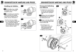
11. Maßzeichnung
196
192
50
110
108
5
40
12. Maße des Beschriftungsstreifens
F1
F2
Tastendurchsichtsfeld 14 x 11
13
y
22
AUF
x
22
22
22
22
297 (DIN A4)
8
ZU
22
22
1. Safety instructions
• Observe the information of this document. Non-observance of the notes, operation which is not in accordance with use as prescribed below, wrong installation or handling can result in serious harm concerning the safety of persons
and plant. The device may only be installed, connected and commissioned by
qualified personnel.
• Disconnect the device externally before doing any work on it.
• In the case of malfunctions or uncertainties please contact the manufacturer.
Tampering with the device can lead to considerable risks for the safety of persons and plant. It is not permitted and leads to an exclusion of any liability and
warranty claims.
More information on programming and operating
the dialogue module is given in the
manual ecomat tdm R 360
2. Function and features
The tdm R 360 is a programmable monitoring and operator module for plc controlled systems. It was specially designed for mobile applications.
• The module communicates with the controller ecomat R 360 via the CAN bus,
• informs the operator of process states, process and measured data of all areas of
the vehicle/plant section,
• indicates messages of the vehicle/plant section,
• and enables the operator to influence the controller of the vehicle/plant section
(input of preset values, triggering of actions).
• The tdm R 360 works on the basis of a freely programmable software which is created by PC and loaded into the module.
Multi-level operator and visualisation menus which enable a complex and flexible
visualisation and process actions can be created.
In addition, simple communication and visualisation processes can be programmed
and executed by the tdm R 360.
The article CR1003 also has a real-time clock and protocol and statistics functions.
This allows to detect, evaluate and display process data.
10
3. Controls and visual indication
1
F1
F2
2
1
Display
with graphic capabilities, backlit, adjustable brightness and contrast
2
LEDs (can be freely allocated)
Function keys
can be freely allocated to menu functions, basic functions are allocated as follows:
= exit menu (Escape);
= open menu / confirm inputs (Enter)
/ = cursor keys up /down, / = cursor keys left/right: selection of menus or menu points,
selection of parameters, alteration of parameter values
4. Preparations for the operation
ENGLISH
First steps
When delivered the tdm R 360 contains a program for diagnostic, communication
and display setting.
• With power on (see section "Electrical connection") the module responds with an
initialisation graphics and carries out a short self-test.
• With the menu "CAN-Setup" you can then configure the CANinterface (default
identifier: transmission channel = 220, reception channel = 221). But these settings
can be made more conveniently via the software.
• Setting the brightness and contrast of the display:
Press the -key and hold it down while setting the brightness with the keys /
and the contrast with the keys / .
11
Programming
1. Create the user program of the tdm R 360 by means of the editor ecolog tdm
R 360 (order no. CP9005). In addition to the operator and visualisation menus it
also contains the data to configure the CAN interface.
2. Remove the clamp cover of the tdm R 360 and connect it with the PC via the serial interface (RS232) or via the CANinterface. The connection cable is available as
an accessory (order no. EC2020).
3. Load the user program into the memory of the tdm R 360 (by means of the corresponding editor menu).
If necessary, the operating system (TOS) can also be loaded via the editor. It is supplied with the editor.
TOS and program updates can be loaded at any time.
If there are problems with the data transfer proceed as follows:
- Configure the serial interface via the editor as follows: 9600 baud - 8 data bits - 2 stop bits
no parity.
- Disconnect the tdm R 360.
- Press 4 of the keys simultaneously, hold them down and reconnect the module.
The module displays "TERMINAL READY FOR UPLOAD". The software can now be transferred.
5. Labelling the function keys
1. Make a paper strip (for dimensions see page 8) and label it according to the
dimensions.
2. Attach its ends onto the supplied plastic strip.
3. Then insert it between the keys and front foil.
6. Mounting
1. Cut 187 x 101 mm out of the control
panel (3), debur and degrease it.
2. Glue the washer (2) to the front of
the control panell (3).
3. Loosen the two wing screws (5) and
remove the clamp cover (4) of the
tdm R 360.
4. Insert the unit (1) into the control
panel (3).
5. Place the clamp cover (4). Tighten the
two wing screws (5) alternately. The
display is then dust-tight and jetproof to IP65 from the front.
12
1
2
3
4
5
7. Electrical connection
Disconnect the system and connect the module via the plug, see page 8 for wiring.
Connect the AMP contact via a 6.3 mm flat-pin plug to ground to comply with the
EMC requirements.
8. Operation
The functions and use of the tdm R 360 depend on the type of the system to be
monitored, on the controller and the user program which was created for the tdm
R 360.
Apart from this, it provides the following basic functions:
• Visualisation
The tdm R 360 shows process states (process data, preset values, actual values, etc.).
To do so, certain groups of data are combined into "images" and displayed by
means of text and graphics. These images contain
- text (fixed and dynamic)
- fixed and dynamic graphics: pictograms, diagrams (representation of values), x/ydiagrams (representation of positions).
The images are cyclically displayed (depending on the program setting) but can also
be called up manually ("scrolling" in images).
• Operator menu
The tdm R 360 enables the input of data in the controller (preset values, actions,
etc.) To do so, operator menus are created with the editor and implemented in the
tdm R 360. The operator
- selects a menu from the list of the available menus,
- opens the menu,
- selects the value to be changed,
- opens the edit mode for this value,
- changes this value,
- confirms the alteration,
- transmits the new value to the controller.
13
ENGLISH
• Message
The tdm R 360 indicates process states, process data, warnings, alarm messages,
etc. by a predefined text when the event to be signalled occurs. Messages appear
at the uppermost position of the processing stack, i.e. they superimpose the current image. They can be created in such a way that the operator must confirm the
message by pressing a key.
Messages are also stored in the memory and can be called up manually.
9. Technical data
Display
supertwisted LCD with graphic capabilities
240 x 64 points, 127 x 34 mm
LED (life 100,000 h)
adjustable in 8/16 steps, temperature compensation
2, 4 or 8 lines, graphics and text (can be mixed)
10/20/40 characters per line (with 2/4/8 lines)
character height [mm]: 14 / 7 / 4 (with 2/4/8 lines)
IBM set 2, other characters possible
Background illumination
Brightness / contrast
Types of representation
Set of characters
Mechanical data
Housing
Dimensions
Cutout
Front panel
Keys
Key cap
Protection rating
Operating temperature
Storage temperature
Vibration
Shock
Weight
Electrical data
Operating voltage
Current consumption
Fuse
EMC
Load-dump resistance
Interfaces/connections
CAN bus + device supply
Serial interface
Communication
Signal output
14
[mm]
[mm]
[°C]
[°C]
[Kg]
[V]
[mA]
panel-mounting housing: stainless steel;
mechanics inside: galvanised steel
196 x 110 x 55 (w x h x d)
187 x 101
5 mm acrylic glass, coated with polyester foil, printed on the back
8 plunger-operated keys
aluminium pane behind polyester foil, mechanically supported
towards the back, protected against vandalism
IP 65 on the front (according to DIN 40050 and IEC 144)
-20 ... +60
-30 ... +80
IEC 60068-2-6
IEC 60068-2-27
1.1
CR1001 / CR1003: 17 ... 32 DC (nominal 24 V DC)
CR1021: 9 ... 19 DC (nominal 12 V DC)
(protected against reverse polarity)
max. 350 (24 V) / max. 650 (12 V)
(with max. display brightness)
electronic with PTC
EN 50081-1, EN 50081-2, EN 50082-1, EN 50082-2
DIN 40839
galvanically separated,
6-pole AMP crimp connector
(to be clipped into place so that it is vibration-resistant)
9-pole Sub-D miniature plug
RS 232/TTY, galvanically separated
9-pole Sub-D miniature plug
via CAN bus with the controller ecomat R 360
12 V DC / 24 V DC (max. 70 mA)
according to operating voltage
(electronically protected against short circuits and overload)
10. Wiring
RS 232 / TTY
RxD +
RxD
TxD
RxD–
GND
1
2
3
4
5
6
7
8
9
CAN- BUS
TxD +
RTS
CTS
TxD–
CAN - SHIELD
NC
CAN - GND
CAN L
NC
5
4
3
2
1
9
8
7
6
CAN - BUS / unit supply
(CAN-BUS-supply)
CAN H
+DC
NC
CAN-GND
CAN H
GND
CAN L
5
6
+DC (unit supply)
3
4
OUT
1
2
GND (unit supply)
11. Scale drawing
196
192
50
110
108
5
40
12. Dimensions of the lable strip
F1
F2
Tastendurchsichtsfeld
transparent
part of the key 14
14 xx 11
11
22
AUF
x
22
22
22
22
ZU
22
22
297 (DIN A4)
ENGLISH
13
y
15
Sachnr. 701405 / 00
10 / 99
Technische Änderungen behalten wir uns ohne vorherige Ankündigung vor.
Papier chlorfrei