1
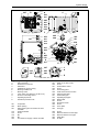
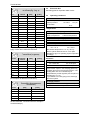
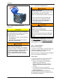
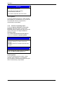
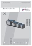
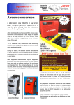
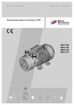
Edition: 12.2009 · 610.44444.40.000 Original operating instructions · English Operating instructions L-BL2 2BL2 041 2BL2 061 2BL2 141 2BL2 251 2BL2 101 2BL2 281 2BL2 341 L-Serie L-Series Flüssigkeitsring Liquid Ring Contents Contents System design ..........................................................................................................................................3 1 Safety ..................................................................................................................................................4 1.1 Definitions .................................................................................................................................4 1.1.1 Safety alert symbol.......................................................................................................4 1.1.2 Signal words.................................................................................................................4 1.2 General safety precautions .......................................................................................................4 1.3 Residual risks............................................................................................................................6 2 Intended Use .......................................................................................................................................7 3 Technical Data ....................................................................................................................................8 3.1 Mechanical data ........................................................................................................................8 3.2 Electrical data..........................................................................................................................10 3.3 Operating conditions ...............................................................................................................10 4 Transport and Handling.....................................................................................................................11 5 Installation .........................................................................................................................................12 5.1 Installation ...............................................................................................................................12 5.2 Electrical connection (motor) ..................................................................................................14 5.3 Filling .......................................................................................................................................17 5.4 Connection of pipes/hoses......................................................................................................18 5.4.1 Inlet connection ..........................................................................................................18 5.4.2 Exhaust-air connection...............................................................................................19 5.5 Accessories.............................................................................................................................19 6 Commissioning ..................................................................................................................................20 6.1 Preparation and start-up .........................................................................................................20 6.2 Shut-down ...............................................................................................................................20 7 Operation...........................................................................................................................................21 7.1 Start-up and shut-down...........................................................................................................21 7.2 Operation within the process ..................................................................................................21 7.2.1 Loss of operating liquid ..............................................................................................21 7.2.2 Increase in operating liquid ........................................................................................22 8 Shutting Down and Longer Standstill ................................................................................................23 8.1 Draining ...................................................................................................................................23 8.2 Preparing for longer shut-down...............................................................................................23 8.3 Storage conditions ..................................................................................................................24 9 Servicing............................................................................................................................................25 9.1 Maintenance............................................................................................................................26 9.2 Repairs/troubleshooting ..........................................................................................................29 9.3 Service/After-sales service......................................................................................................33 9.4 Decontamination and Declaration of Clearance .....................................................................33 10 Disposal.............................................................................................................................................33 EU declaration of conformity ..................................................................................................................34 Form for statement on safety .................................................................................................................35 © 2009 Gardner Denver Deutschland GmbH · Industriestraße 26 · 97616 Bad Neustadt · Germany Replication, distribution and / or editing of this document and the use and distribution of its content is prohibited unless explicitly permitted. Violation obligates compensation for damages. All rights reserved in case of the issue of a patent, utility patent or design patent. System design System design 007 A B 030 027 D C 096 001 025 079 058 095 005 F 023 066 065 085 052 057 010 012 032 031 039 H 086 043 064 G 080 019 K 037 040 025 060 060 2BL2 141 041 J K 007 025 J E L_300 E 2BL2 251, 281, 341 Fig. 1: System design A B C D E F G H J K Inlet connection Exhaust-air connection Cable inlet Installed unit (L-BV7 pump) Draining installed unit Draining cooler 3-way valve (only 2BL2 041 to 2BL2 141) Screw-in connecting sleeve Operating liquid hole Cavitation protection hole 001 005 007 U-separator Drain opening Filling opening and connection for drain controller Fill level indicator Screw Nut Nut Connection for supply or drain controller 010 012 019 023 025 © Gardner Denver Deutschland GmbH 3 / 36 027 030 031 032 037 039 040 041 043 052 057 058 060 064 065 Water or air water cooler Screw Condensation cooler Screw Connecting piece Intake hose with check valve Injection water pipe Condensate pipe Operating liquid pipe Rating plate Screw Protective screen Screw Cover plate Cord grip 066 079 080 095 096 Screw Restrictor sleeve for water pipe Restrictor sleeve for air pipe Water filter Air filter 610.44444.40.000 Safety 1 Safety 1.1 CAUTION Definitions Danger of damage. To point out dangers and important information, the following signal words and symbols are used in these operating instructions: 1.1.1 Indicates a potentially hazardous situation that may result in property damage if the corresponding measures are not taken. NOTICE Safety alert symbol The safety alert symbol is located in the safety precautions in the highlighted heading field on the left next to the signal word (DANGER, WARNING, CAUTION). Safety precautions with a safety alert symbol indicate a danger of injuries. Be sure to follow these safety precautions to protect against injuries or death! Safety precautions without a safety alert symbol indicate a danger of damage. 1.1.2 Signal words DANGER The signal words are located in the safety precautions in the WARNING highlighted heading field. CAUTION They follow a certain hierarchy and indicate (in conjunction with the NOTICE safety alert symbol, see Chapter 1.1.1) the seriousness of NOTE the danger and the type of warning. See the following explanations: DANGER Indicates a possible disadvantage, i.e. undesirable conditions or consequences can occur if the corresponding measures are not taken. NOTE Indicates a possible advantage if the corresponding measures are taken; tip. 1.2 General safety precautions WARNING Improper use of the system can result in serious or even fatal injuries! These operating instructions must have been completely read and understood before the start of any work with or on the system, must be strictly observed, must be available at the system operating location. Danger of injuries. Indicates an imminently hazardous situation, that will result in death or serious injury if the corresponding measures are not taken. WARNING Danger of injuries. Indicates a potentially hazardous situation, that could result in death or serious injury if the corresponding measures are not taken. WARNING Improper use of the system can result in serious or even fatal injuries! Only operate the system for the purposes indicated under "Intended Use"! with fluids specified under "Proper use"! with the values indicated under 'Technical Data'! WARNING CAUTION Danger of injuries. Indicates a potentially hazardous situation, that may result in minor or moderate injury if the corresponding measures are not taken. 610.44444.40.000 Improper use of the system can result in serious or even fatal injuries!! All work on and with the system (transport, installation, commissioning, shut-down, maintenance, disposal) may only be carried out by trained, reliable personnel! 4 / 36 © Gardner Denver Deutschland GmbH Safety WARNING When working on the system, there is danger of injury, e.g. due to cutting/cutting off, crushing and burns! During all work on and with the system (transport, installation, operation, shut-down, maintenance, disposal) wear personal safety equipment (safety helmet, protective gloves, safety shoes)! WARNING Danger from vacuum! Danger due to escaping fluid! Relieve pressure or vacuum before beginning to work on the system! Make sure that pipes/hoses and vessels to be opened have been relieved of pressure or vacuum and that no fluids might leak out before loosening any connectors and fasteners. WARNING Hair and clothing can be pulled into the system or caught and wound up by moving parts! Do not wear long, loose hair or loose-fitting clothes! WARNING Danger from vacuum! Danger due to escaping fluid! Use a hair net! Carry out the following tasks prior to commissioning, after every disassembly and reassembly and at regular intervals: Electrical danger! Check pipe/hose connections, pipes/hoses and vessels for sufficient strength, tightness and secure fixing! Check fasteners for secure seating! DANGER Before beginning work on the system, the following measures must be carried out: Deenergise. Secure against being switched on again. Determine whether deenergised. Ground and short-circuit. Cover or block off adjacent energised parts. DANGER WARNING Danger from vacuum! Do not operate the unit unless the pipe / hose has been fitted to the inlet connection! In particular, do not look into the inlet connection or move your eyes in front of the inlet connection opening if the system might start up and generate a vacuum! Electrical danger! WARNING Work on electrical installations may be carried out by trained and authorised electricians only! Danger due to rotating parts! DANGER Electrical danger! Do not open the motor terminal box unless absence of electricity has been ensured! Only operate the system when fully assembled: with hoses connected to inlet and discharge connection as well as to operating liquid connection of installed unit with the pipes/hoses and fasteners of the operating-liquid circuit mounted with cover plate and water cooler of separator mounted. Do not disassemble unless the system has been shut down and come to a complete standstill! Consider that the system has a certain run-out! © Gardner Denver Deutschland GmbH 5 / 36 610.44444.40.000 Safety WARNING Danger due to rotating parts! Do not reach into the installed unit through opened intake or discharge connection! Do not insert objects into the installed unit through the openings! NOTE For the system design, see Fig. 1, Pg. 3. The item numbers (Item) specified in the text refer to this illustration. 1.3 Residual risks WARNING Danger of burns/scalding from hot fluids and hot surfaces of the installed unit! Allow to cool after shut-down! CAUTION WARNING Danger zone: Not surfaces of installed unit. Hazard: Burns/scalding possible. Protective measures: Danger from excessive pressure! Attach warning sign "Warning! Hot surface!" . Danger from system clogging! Dirt can enter the system through the exhaustair connection! Clogging is possible! Do not remove the protective cap from the discharge connection! WARNING Danger zone: External fan of installed unit. Hazard: NOTICE The pumped gases/vapours are expelled into the surrounding area via the exhaust-air connection. They are not directed through a pipe or a hose. If delivery-side piping is desired: Enquiry with Service is absolutely necessary! Long, open hair may be drawn into the external fan of the installed unit with the cover plate and protective screen of the system removed! Protective measures: Wear hair net! WARNING Danger from caustic or toxic fluids! In case of corrosive of toxic fluids (operating liquid, pumped gases/vapours): Enquiry with Service is absolutely necessary! Wear appropriate personal protective equipment (protective gloves, safety goggles, respiratory protection) when working on or near the system. If appropriate, attach appropriate warning sign(s) to the system, e.g. 'Warning! Corrosive materials!', 'Warning! Harmful or irritant material!' or 'Warning! Toxic material'. 610.44444.40.000 6 / 36 © Gardner Denver Deutschland GmbH Intended Use 2 Intended Use These operating instructions apply to vacuum pumps of the L-BL2 series, models 2BL2 041, 2BL2 061, 2BL2 101, 2BL2 141, 2BL2 251, 2BL2 281 and 2BL2 341 contain instructions bearing on transport and handling, installation, commissioning, operation, shut-down, storage, servicing and disposal of the L-BL2, must be completely read and understood by all operating and servicing personnel before beginning to work with or on the L-BL2, must be strictly observed, must be available at the site of operation of the L-BL2. It is prohibited These persons must be trained and authorised for the work to be carried out. Work on electrical installations may be carried out by trained and authorised electricians only. are systems for generating a vacuum. contain a liquid-ring vacuum pump of the LBV7 series, model 2BV7 or L-BV5, model 2BV5 (in the following referred to as "unit"), which is installed in a liquid separator (in the following referred to as "separator"). are used to extract, transport and compress the following pumped gases/vapours: – all dry and moist gases, which are not explosive, aggressive or toxic, – preferably air or air/vapor mixtures. – For gases/vapours that differ, an enquiry must be made with the Service Department. are designed for operation with the following operating liquids: – with a pH of 6 to 9, which is free of solid materials (such as sand), – usually normal tap water. – If the pH values or operating liquids differ, it is necessary to contact the Service Department. release gases with the following properties into the environment during operation: – discharge temperature ambient temperature, – discharge pressure ambient pressure, – absolutely clean and dust-free. © Gardner Denver Deutschland GmbH When operating the L-BL2, the limits listed in Chapter 3, "Technical Data", Pg. 8 ff. must always be complied with. Foreseeable Misuse About the operating and servicing personnel of the L-BL2: The L-BL2s exist in the following designs: – 2BL2 041 – 2BL2 061 – 2BL2 101 – 2BL2 141 – 2BL2 251 – 2BL2 281 – 2BL2 341 are oil-free and non-contacting units. are air-cooled units. are intended for industrial applications. are designed for continuous operation. to use the L-BL2 in non-industrial applications, unless the necessary protection is provided on the system, e.g. guards suitable for children's fingers, to use the device in rooms in which explosive gases can occur if the S _200 is not expressly intended for this purpose, to extract, to deliver and to compress explosive, flammable, corrosive or toxic fluids, unless the S _200 is specifically designed for this purpose, to operate the L-BL2 with values other than those specified in Chapter 3, "Technical Data", Pg. 8 ff. Any unauthorised modifications of the L-BL2 are prohibited for safety reasons. Maintenance and repair work by the operator are only permitted in the scope described in these operating instructions. Any maintenance and repair work going beyond this may only be conducted by companies authorised by the manufacturer (enquiry with the Service Department necessary). This especially applies to the unit installed in the L-BL2 (liquid-ring vacuum pump of the L-BV7 series, model 2BV7 or L-BV5, model 2BV5): The installed unit may be neither removed nor dismantled! any maintenance and repair work, such as replacing worn or defective components, may only be carried out by companies authorised by the manufacturer (please contact the Service Department). 7 / 36 610.44444.40.000 Technical Data 3 Technical Data 3.1 Filling capacity for antiliming agent Mechanical data Type Weight Weight (when not filled with water) approx. [kg] approx. [lbs] 2BL2 041 2 4.41 2BL2 061 4 8.82 2BL2 101 4 8.82 approx. [kg] approx. [lbs] 2BL2 141 5 11 2BL2 041 38 83.8 2BL2 251 8 17.6 2BL2 061 55 121 2BL2 281 8 17.6 2BL2 101 68 150 2BL2 341 8 17.6 (Use pure granulated citric acid as antiliming agent. The specified filling quantities for citric acid refer to the medium filling of the separator with operating liquid.) Type 2BL2 141 105 232 2BL2 251 195 430 2BL2 281 210 463 2BL2 341 225 496 Weight (when filled with water) Type approx. [kg] approx. [lbs] 2BL2 041 61 134 2BL2 061 97 214 2BL2 101 110 243 161 355 290 640 2BL2 141 2BL2 251 2BL2 281 305 673 2BL2 341 320 706 Filling capacity of separator Filling capacity for operating liquid max. [l] max. [gal(US)] max. [gal(UK)] 2BL2 041 23 6.08 5.06 2BL2 061 42 11.1 9.24 2BL2 101 42 11.1 9.24 2BL2 141 56 14.8 12.3 2BL2 251 94 24.8 20.7 2BL2 281 94 24.8 20.7 2BL2 341 94 24.8 20.7 Type (Normal tap water should usually be used as operating liquid.) Filling quantity of installed unit Filling quantity for anti-corrosive agent Type [l] [gal (US)] [gal (UK)] 2BL2 041 0.6 0.159 0.132 2BL2 061 1.0 0.264 0.220 2BL2 101 1.0 0.264 0.220 2BL2 141 1.0 0.264 0.220 2BL2 251 5.5 1.453 1.210 2BL2 281 6.3 1.664 1.386 2BL2 341 7.0 1.849 1.540 (To ensure sufficient protection, the entire interior of the installed unit must be filled with anticorrosive agent. Use only anti-corrosive agent based on ethylene glycol without additives, e.g. Antifrogen from Hoechst!) Filling quantity for antiliming liquid Type [l] [gal (US)] [gal (UK)] 2BL2 041 0.6 0.159 0.132 2BL2 061 1.0 0.264 0.220 2BL2 101 1.0 0.264 0.220 2BL2 141 1.0 0.264 0.220 2BL2 251 5.5 1.453 1.210 2BL2 281 6.3 1.664 1.386 2BL2 341 7.0 1.849 1.540 (Use 10 % ethanoic acid as antiliming liquid.) 610.44444.40.000 8 / 36 © Gardner Denver Deutschland GmbH Technical Data Minimum distances for heat dissipation Distance E Minimum distance A Type [m] [ft] 2BL2 041 ≥ 0.5 2BL2 061 ≥ 0.7 Type 2BL2 101 2BL2 141 ≥ 0.7 ≥ 0.8 [mm] [inches] 2BL2 041 345 13.6 ≥ 1.64 2BL2 061 450 17.7 ≥ 2.30 2BL2 101 450 17.7 ≥ 2.30 2BL2 141 570 22.4 ≥ 2.60 2BL2 251 755 29.7 755 29.7 755 29.7 2BL2 251 ≥ 1.0 ≥ 3.28 2BL2 281 2BL2 281 ≥ 1.0 ≥ 3.28 2BL2 341 2BL2 341 ≥ 1.0 ≥ 3.28 (The dimensions are shown in Fig. 3, Pg. 13.) (The dimensions are shown in Fig. 3, Pg. 13.) Type Distance F Minimum distance B Type [m] [ft] 2BL2 041 [mm] [inches] --- --- 225 8.9 2BL2 041 ≥ 1.4 ≥ 4.59 2BL2 061 2BL2 061 ≥ 1.6 ≥ 5.25 2BL2 101 225 8.9 2BL2 101 ≥ 1.6 ≥ 5.25 2BL2 141 285 11.2 2BL2 141 ≥ 1.8 ≥ 5.90 2BL2 251 377 14.8 2BL2 251 ≥ 1.9 ≥ 6.23 2BL2 281 377 14.8 ≥ 6.23 2BL2 341 377 14.8 ≥ 6.23 (The dimensions are shown in Fig. 3, Pg. 11.) 2BL2 281 2BL2 341 ≥ 1.9 ≥ 1.9 (The dimensions are shown in Fig. 3, Pg. 13.) Type Minimum distance C Noise level 1 Measuring-surface sound-pressure level as per EN ISO 3744, measured at 1 m [3.28 ft] distance with moderate throttling (100 mbar abs. [1.45 psia]) and connected lines, tolerance 3 dB (A). [m] [ft] 2BL2 041 ≥ 0.4 ≥ 1.31 2BL2 061 ≥ 0.4 ≥ 1.31 2BL2 101 ≥ 0.4 ≥ 1.31 2BL2 141 ≥ 0.4 ≥ 1.31 2BL2 251 ≥ 0.4 ≥ 1.31 Type ≥ 1.31 2BL2 041 70 ≥ 1.31 2BL2 061 70 2BL2 101 74 2BL2 281 2BL2 341 ≥ 0.4 ≥ 0.4 (The dimensions are shown in Fig. 3, Pg. 13.) 1-m measuring-surface sound pressure level L [dB (A)] at 50 Hz: 2BL2 141 Spacing of securing eyes Distance D Type 70 74 2BL2 281 76 2BL2 341 73 [inches] 2BL2 041 360 14.2 2BL2 061 495 19.5 Operating speed 2BL2 101 495 19.5 See rating plate. 2BL2 141 585 23 2BL2 251 715 28.1 2BL2 281 715 28.1 2BL2 341 715 28.1 Tightening torques Tightening torques for screws (Fig. 1, Pg. 3) Pos.: [Nm] [ft lbs] 005 2.7 - 3.3 1.99 - 2.43 007 2.7 - 3.3 1.99 - 2.43 0.72 - 0.88 0.53 - 0.65 012 © Gardner Denver Deutschland GmbH 77 2BL2 251 [mm] (The dimensions are shown in Fig. 3, Pg. 13.) at 60 Hz: 9 / 36 Thread E-JOT4 610.44444.40.000 Technical Data 3.2 Tightening torques for screws (Fig. 1, Pg. 3) Pos.: Thread [Nm] [ft lbs] 019 M8 13.5 - 16.5 9.96 - 12.2 019 M10 21.6 - 26.4 15.9 - 19.5 023 M8 8.1 - 9.9 6.0 - 7.3 023 M10 025 See rating plate on separator water cooler. 3.3 Default conditions Ambient temperature 13.5 - 16.5 9.96 - 12.2 2.7 - 3.3 1.99 - 2.43 Air saturation M6/M8 8.1 - 9.9 6.0 - 7.3 032 E-JOT5 1.1 - 1.3 0.8 - 0.96 032 M6 4.5 - 5.5 3.3 - 4.05 057 St 4,2 2.7 - 3.3 1.99 - 2.43 060 M6 2.7 - 3.3 1.99 - 2.43 066 E-JOT4 0.72 - 0.88 0.53 - 0.65 E G¼ 2.25 - 2.75 1.66 - 2.0 E G⅜ 6.3 - 7.7 4.65 - 5.68 2.7 - 3.3 1.99 - 2.43 [Nm] [ft lbs] M4 5.6 1.26 - 1.54 0.93 - 1.14 M5 5.6 2.7 - 3.3 1.99 - 2.43 M6 8.8 7.2 - 8.8 5.3 - 6.5 M8 8.8 18 - 22 13.3 - 16.2 M10 8.8 36 - 44 26.6 - 32.5 M12 8.8 63 - 77 46.5 - 56.8 M16 5.6 90 - 110 66.4 - 81.1 Delivery temperature [Nm] [ft lbs] 0.9 - 1.1 0.66 - 0.81 M5 2.0 - 2.4 1.47 - 1.77 M6 2.7 - 3.3 1.99 - 2.43 M8 6.3 - 7.7 4.65 - 5.68 M10 10 - 12 7.34 - 8.85 max. +60 °C max. +140 °F Ambient temperature Temperature of operating liquid max. +60 °C max. +140 °F Ambient temperature max. +40 °C max. +104 °F min. +10 °C min. +50 °F With ambient temperature < 10 °C (< 50 °F): Observe yellow adhesive label on cover plate. Add ethylene glycol to operating liquid in separator accordingly. Pressures Inlet pressure min. 5 kPa abs. min. 0.725 psia max. 80 kPa abs. max. 11.6 psia At inlet pressures > 35 kPa abs. [5.08 psia], the share of water vapour in the escaping gases may be slightly above that of the gases sucked in. The resulting water loss can automatically be compensated by a feed regulator (see Chapter 5.5, "Accessories", Pg. 19). It is prohibited to connect piping to the discharge side of the system! Discharge pressure Tightening torques for electrical connections (terminal boardconnections) M4 50 % Intake temperature (These values apply to screw connections with the exception of electrical connections.) Thread +68 °F 14.7 psi Temperatures of pumped gases/vapours Tightening torques for screw connections (in general) Property classes +20 °C 101.3 kPa Temperatures The values specified here for tightening torques apply unless other values are indicated. Thread Operating conditions Ambient pressure 030 Clamps Electrical data approx. 101.3 kPa approx. 14.7 psi Ambient pressure These values for electrical connections apply to all terminal board connections with the exception of terminal strips.) 610.44444.40.000 10 / 36 © Gardner Denver Deutschland GmbH Transport and Handling 4 Transport and Handling Transport with a crane and lifting belts, with forklift truck or with low-lift platform truck. WARNING Improper use of the system can result in serious or even fatal injuries!! Have you read the safety precautions in Chapter 1, "Safety", Pg. 4 f.? Otherwise you may not carry out any work with or on the system! WARNING Danger from tipping or falling loads! Prior to transport and handling make sure that all components are securely assembled and secure or remove all components the fasteners of which have been loosened! Manual handling: WARNING Danger from lifting heavy loads! Manual handling of the unit is only permitted within the following limits: max. 30 kg [max. 66 lbs] for men max. 10 kg [max. 22 lbs] for women max. 5 kg [max. 11 lbs] for pregnant women For the weight of the system, see Chapter 3.1, "Mechanical data", Section "Weight", Pg. 8. Above these limits, suitable lifting equipment and/or means of transport must be used! Transport with lifting equipment: WARNING Fig. 2: Attachment points Attach the strap belts as shown in Fig. 2, Pg. 11: Use two lifting belts routed along below the system. The lifting belts should be securely seated in the recesses shaped into the lower edges (two on each of the long sides) of the system so as to prevent the system from slipping out of them. The lifting belts must be sufficiently long (spread angle smaller than 90°). Make sure that no damage is caused to any attached fittings. Danger from tipping or falling loads! When transporting with lifting equipment, observe the following basic rules: Use only suitable lifting gear (e.g. belts or ropes) and means of transport (e.g. forklift truck, low-lift platform truck, crane). The lifting capacity of lifting equipment and lifting gear must be at least equal to the system's weight. For the weight of the system, see Chapter 3.1, "Mechanical data", Section "Weight", Pg. 8. The system must be secured so that it cannot tip or fall. Do not stand or walk under suspended loads! © Gardner Denver Deutschland GmbH 11 / 36 610.44444.40.000 Installation 5 Installation CAUTION WARNING Improper use of the system can result in serious or even fatal injuries!! Have you read the safety precautions in Chapter 1, "Safety", Pg. 4 f.? Otherwise you may not carry out any work with or on the system! NOTE For the system design, see Fig. 1, Pg. 3. The item numbers (Item) specified in the text refer to this illustration. 5.1 Installation CAUTION Danger of damage to the system due to overheating! When installing the system, make sure that heat dissipation and cooling are not obstructed. The minimum distances specified in Chapter 3.1, "Mechanical data", Section "Minimum distances for heat dissipation", Pg. 9 must be complied with. Discharge air of other machines/devices may not be directly sucked in again! WARNING Danger from system tipping over or falling! If the system is installed on moveable machine parts or at a great height without any other protection against falling down, it must by all means be bolted to the bearing surface via the securing eyes in its feet. Danger of crushing from system tipping over! In the unmounted state, the system can easily tip due to its weight distribution! Wear gloves and safety shoes! Handle the system with the appropriate care! CAUTION Danger of tripping and falling! Make sure the system does not present a danger of tripping! Block off the system with a guard fence or mark with red-and-white tape etc. if necessary. WARNING Electrical danger! The system must be installed so that the electrical device cannot be damaged by external influences! NOTE Note on later transport! Install the system with the feet on strips or similar supports to simplify transport later, e.g. with a low-lift platform truck! Space requirement and minimum distances: The space requirement and positioning of the hole for installing and securing the system are shown in Fig. 3, Pg. 11. For minimum clearances for heat dissipation and cooling, see Chapter 3.1, "Mechanical data", Section "Minimum distances for heat dissipation", Pg. 9. Spacing of securing eyes: see Chapter 3.1, "Mechanical data", Section "Spacing of securing eyes", Pg. 9. In particular, the feed pipes must be securely routed, e.g. in cable ducts or in the floor. 610.44444.40.000 12 / 36 © Gardner Denver Deutschland GmbH Installation B A C 3 C 3 3 1 2 F D E Fig. 3: Minimum distances for heat dissipation and spacing of securing eyes A – C: D – F: Minimum clearance for heat dissipation Spacing of securing eyes 1 2 3 See Chapter 3.1, "Mechanical data", Pg. 8 for dimensions. Cooling air inlet Cooling air outlet Wall The points on the system for measuring the vibration speed are shown in Fig. 4, Pg. 13. Installation conditions: The system must be installed as follows: on flat, level surfaces, on stationary (fixed) surfaces or structures, with the feet facing downward (no ringing off, e.g. with the feet on the wall), at a maximum height of 1000 m [3280 ft] above sea level. At installation altitudes of more than 1,000 m [3,280 ft] above sea level, the Service Department must be consulted. Observe the following when installing the system: The load-bearing capacity of the installation surface must at least be designed for the weight of the system. The vibration behaviour at the operating location must be taken into account. The total vibrations of the system are dependent on the following factors: – the characteristic vibrations of the system, – the alignment and installation, – the condition (vibration behaviour) of the load-bearing surface, – the influences by vibrations of other parts and system components (external vibrations). Fig. 4: Points for measuring the vibration speed The maximum permissible value for vibrations is veff = 4.5 mm/s [0.177"/s]. To ensure proper operation and a long service life of the system, this value may not be exceeded. Generally, this value can be adhered to without a special foundation or a special base plate. © Gardner Denver Deutschland GmbH 13 / 36 610.44444.40.000 Installation Securing: DANGER There are two options: Install the system without securing. OR Screw the feet of the system to the surface with suitable fasteners. – Models 2BL2 041 - 141: Screws 4 x M10 Washers as per ISO 7093-1 Tightening torque: 10 Nm [7.38 ft lbs] – Models 2BL2 251 - 341: Screws 4 x M12 Washers as per ISO 7093-1 Tightening torque: 20 Nm [14.81 ft lbs] Electrical danger! Replace loose connections, singed or burned cables immediately! DANGER Electrical danger! Lay the electrical connecting cables so that they cannot be damaged by external influences and are free from tensile stress! WARNING CAUTION With the 2BL2 341 the 4 adjustment screws of the hexagonal feet (see Fig. 1, Pg. 3) and the 3 strips of the separator must make contact over the entire contact surface on the floor or the raised sections. Danger due to gauge pressure and vacuum! Danger due to escaping fluid! Before beginning work on the system or line: Interrupt supply of operating liquid. Vent lines (depressurise). CAUTION 5.2 Electrical connection (motor) DANGER Electrical danger! Improper behaviour can result in severe injuries and damage! DANGER Electrical danger! The electrical connection may be carried out by trained and authorised electricians only! Incorrect connection of the motor can lead to serious damage to the system! Regulations: The electrical connection must be carried out as follows: according to the applicable national and local laws and regulations, according to the applicable system-dependent prescriptions and requirements, according to the applicable regulations of the utility company. Electrical power supply: DANGER Electrical danger! Observe the rating plate. It is imperative that the operating conditions correspond to the data given on the rating plate! Before beginning work on the system, the following measures must be carried out: Deviations permissible without reduction in performance: ±5 % voltage deviation ±2 % frequency deviation Deenergise. Secure against being switched on again. Determine whether deenergised. Ground and short-circuit. Cover or block off adjacent energised parts. 610.44444.40.000 Fit connecting cable: Use a flexible cable as the electrical connecting cable. Open system: Remove cover plate. 14 / 36 © Gardner Denver Deutschland GmbH Installation Fig. 5: Remove cover plate: Unscrew screws Insert the connecting cable: Thread the connecting cable into the cord grips on the side panel of the separator and push it through the cable inlet into the interior of the separator. Route the connecting cable into the terminal box of the installed unit via the cable entry opening. In order to relieve strain, secure the connecting cable as follows: – via the cable gland on the terminal box of the installed unit – via the cord grips on the outside of the separator – Tightening torques: see Chapter 3.1, "Mechanical data", Section "Tightening torques", Pg. 9. Fig. 6: Strain relief: Cord grips on the outside of the separator Connection to drive-motor terminal box: Carry out the connection and the arrangement of the jumpers in accordance with the circuit diagram in the terminal box. Connect the protective conductor to the terminal with the following symbol: The electrical connection must be carried out as follows: The electrical connection must be permanently safe. There may be no protruding wire ends. Clearance between bare live parts and between bare live parts and ground: ≥ 5.5 mm [0.217"] (at a nominal voltage of UN ≤ 690 V). Tightening torques for terminal plate connections: see Chapter 3.1, "Mechanical data", Section "Tightening torques", Pg. 9. Use suitable cable lugs. For terminals with clamping straps, the conductors must be inserted so that approximately the same clamping height results on both sides of the bar. Individual conductors must therefore be bent into a U-shape or connected with a cable lug. All conductors under outer angled grounding brackets must be bent into a "U" shape. © Gardner Denver Deutschland GmbH 15 / 36 610.44444.40.000 Installation This also applies to: the protective conductor, the outer ground conductor. Both conductors can be recognised from their colour (green/yellow). WARNING Electrical danger! Clearance between bare live parts and between bare live parts and ground: at least 5.5 mm [0.217"] (at a nominal voltage of Vn ≤ 690V) Make sure there are no protruding pieces of wire! CAUTION If the installed unit is run dry, the mechanical seal will be destroyed in a matter of seconds! DO NOT switch on until the following conditions are met: The separator must be correctly filled with operating liquid. The interior of the installed unit must be filled with operating liquid. Check direction of rotation: Make sure that the following conditions are met: – The separator must be correctly filled with operating liquid (watch fill level indicator). WARNING Electrical danger! The terminal box must be free from foreign bodies, dirt, humidity. Terminal box cover and cable entries must be tightly closed so as to make them dustproof and waterproof. Check for tightness at regular intervals. For motor overload protection: Use motor circuit breakers. Set the motor circuit breakers to the nominal current specified on the rating plate. We recommend using slow-acting motor circuit breakers. Close system: Fit cover plate. WARNING The interior of the installed unit must be filled with operating liquid. – The separator cover plate must be mounted. WARNING Danger from vacuum! If there is a danger that the system could suck in: Do not go near the inlet connection with long, open hair or loose fitting clothing, Do not look into the inlet connection or move your eyes in front of the inlet connection opening. Do NOT connect the intake line to the inlet connection yet. Briefly turn power ON. If the rotating direction is correct, cooling air immediately exits from the protective screen. Turn power OFF again. If necessary, reverse the direction of rotation of the motor. Danger from rotating external fan of installed unit! Only operate the system with the protective screen and cover plate installed! – WARNING Malfunctions can result in serious damage and injuries! In case of conspicuous irregularities which indicate malfunctions, take the following measures: If in doubt, shut off the operating materials concerned immediately! Determine cause immediately and eliminate! Also see Chapter 9, "Servicing", Pg. 25. 610.44444.40.000 16 / 36 © Gardner Denver Deutschland GmbH Installation 5.3 Filling WARNING Improper use of the system can result in serious or even fatal injuries!! Only operate the system for the purposes indicated under "Intended Use"! with the fluids specified under "Proper use"! with the values indicated under 'Technical Data'! WARNING Danger from caustic or toxic fluids! In case of corrosive of toxic fluids (operating liquid, pumped gases/vapours): Enquiry with Service is absolutely necessary! Wear appropriate personal protective equipment (protective gloves, safety goggles, respiratory protection) when working on or near the system. Fig. 8: Filling separator Models 2BL2 251 - 341 (via the filling opening) Check the liquid level in the separator: Check via the fill level indicator (Item 010). When doing so, watch the maximum operating liquid level. NOTICE If appropriate, attach appropriate warning sign(s) to the system, e.g. 'Warning! Corrosive materials!', 'Warning! Harmful or irritant material!' or 'Warning! Toxic material'. Max. operating-liquid level: Proceed as follows: Do not fill the separator above this level! Lower edge of the fill opening (Item 007) = level-indicator pointer at 1 (Item 010). Fill the separator: Fill operating liquid (usually ordinary tap water) into the separator via the fill opening (Item 007), Filling amount: See Chapter 3.1, "Mechanical data", Pg. 8. When the unit is filled for the first time: Fill installed unit: Pour additional operating liquid into the inlet connection (Item A) of the system so that operating liquid flows into the interior of the installed unit. Models 2BL2 041 - 2BL2 141: 1.5 l [0.396 gal (US); 0.330 gal (UK)] Models 2BL2 251 - 2BL2 341: 7.0 l [1.32 gal (US); 1.1 gal (UK)] Fig. 7: Filling separator Models 2BL2 041 - 141 (via the filling opening) © Gardner Denver Deutschland GmbH 17 / 36 610.44444.40.000 Installation 5.4 Connection of pipes/hoses WARNING Danger from vacuum! Do not operate the unit unless the pipe / hose has been fitted to the inlet connection! If there is a danger that the system could suck in: Do not go near the inlet connection with long, open hair or loose fitting clothing, Do not look into the inlet connection or move your eyes in front of the inlet connection opening. Fig. 9: Filling installed unit (via inlet connection) CAUTION If the installed unit is run dry, the mechanical seal will be destroyed in a matter of seconds! DO NOT switch on until the following conditions are met: The separator must be correctly filled with operating liquid. The interior of the installed unit must be filled with operating liquid. WARNING Danger from vacuum! Danger due to escaping fluid! During operation connected pipes and vessels are vacuumised! Make sure that all connections are sufficiently tight! Use only pipes and vessels of sufficient strength! The pumped gases/vapours are sucked in via the inlet connection (see Chapter 5.4.1, Pg. 18) and discharged via the exhaust-air connection (see Chapter 5.4.2, Pg. 19). WARNING Danger due to escaping fluid! Make sure that all openings in the separator (feed/drain regulator connection, fill opening, drain opening) are tightly closed (by means of screwed-in bung plugs or installed feed regulator, drain regulator and drain valve) when the separator is filled with operating liquid. 5.4.1 Inlet connection Remove sealing plug To prevent the penetration of foreign bodies, the connection opening on the inlet connection (Item A) is sealed off on delivery. Do not remove the sealing plug until immediately before connecting the pipes/hoses. Check valve: In the following cases a check valve must be attached to the inlet connection (Item A): If two or more systems are operated in parallel, e.g. reserve system. (Note: A separate check valve must be attached to the inlet connection on each system.) If a vacuum can occur for more than one minute in the connected intake line on the system switched off. The check valve prevents the backflow of pumped gases/vapours from the system during an interruption in operation. 610.44444.40.000 18 / 36 © Gardner Denver Deutschland GmbH Installation Connect the inlet pipe: 5.4.2 Connect the system-side line for the pumped gases/vapours (intake line) to the connecting piece of the inlet connection (Item 037). The pumped gases/vapours are expelled into the surrounding area via the exhaust-air connection (Item B). They are not directed through a pipe or a hose. As a result, no assembly is required here. 1 2 3 Exhaust-air connection CAUTION Danger from excessive pressure! Danger from system clogging! Do not remove the protective cap from the exhaust-air connection! NOTICE Fig. 10: Connection of inlet line on connecting piece of inlet connection 1 2 3 Inlet line Connection thread Connecting piece CAUTION Danger of damage to connecting piece! The connection thread on the connecting piece of the inlet connection is made of plastic, and can therefore easily be damaged. Exercise the appropriate caution when connecting the inlet line. If delivery-side piping is desired: Enquiry with Service is absolutely necessary! 5.5 Accessories The following accessories are available according to our catalogue: Inlet Filter Vacuum Control Valve Feed Regulator Outlet Regulator Electrical Level Switch Drain Valve The tightening torque must always be adjusted to match the connection thread material. NOTICE Attach pipes/hoses free of mechanical tensions. Support the weight of the pipes/hoses. Fig. 11: Accessories © Gardner Denver Deutschland GmbH 19 / 36 610.44444.40.000 Commissioning 6 Commissioning 6.1 Preparation and start-up Proceed as follows: WARNING Improper use of the system can result in serious or even fatal injuries!! Make sure that the following conditions are met: – The separator must be correctly filled with operating liquid. (watch fill level indicator). Have you read the safety precautions in Chapter 1, "Safety", Pg. 4 f.? Otherwise you may not carry out any work with or on the system! WARNING Danger from vacuum! – The interior of the installed unit must be filled with operating liquid. – The separator cover plate must be mounted. Turn power ON. The system begins to intake the pumped gases/vapours. Danger due to escaping fluid! NOTE Danger due to rotating parts! The system may only be put into operation when the following conditions are met: If, on being put into service for the first time, the system does not generate a vacuum: The hoses on the inlet and discharge connection and on the operating liquid connection of the installed unit are connected. The cover plate and the water cooler of the separator are fitted. The lines and connection elements of the operating liquid circuit are fitted. The line on the system inlet connection is connected. The pipe/hose connections, pipes/hoses and vessels have been checked for sufficient strength and freedom from leaks! The fasteners have been checked for secure seating. briefly throttle or close and reopen the inlet side. CAUTION If the installed unit is run dry, the mechanical seal will be destroyed in a matter of seconds! DO NOT switch on until the following conditions are met: 6.2 Shut-down Generally speaking, the system may be shut down in any operating condition (i.e. regardless of the actual pressure, temperature, etc.). Take into consideration, however, whether the process of your line allows for interrupting the operation of the system. Proceed as follows: Turn power OFF. The system interrupts the intake of the pumped gases/vapours. In case the unit is not to be put into service again for an extended period of time: observe the instructions in Chapter 8, "Shutting Down and Longer Standstill", Pg. 23. The separator must be correctly filled with operating liquid. The interior of the installed unit must be filled with operating liquid. NOTE For the system design, see Fig. 1, Pg. 3. The item numbers (Item) specified in the text refer to this illustration. 610.44444.40.000 20 / 36 © Gardner Denver Deutschland GmbH Operation 7 Operation Start-up and shut-down in normal operation is identical to the procedure for commissioning. WARNING Improper use of the system can result in serious or even fatal injuries!! Have you read the safety precautions in Chapter 1, "Safety", Pg. 4 f.? Otherwise you may not carry out any work with or on the system! Position STANDARD Also be sure to read the safety precautions in Chapter 6, "Commissioning", Pg. 20! Fig. 12: 3-way valve (only 2BL2 041 - 141) NOTE 7.2.1 Start-up and shut-down NOTICE See: Check the operating-liquid level in the separator regularly by means of the level indicator! Chapter 6.1, "Preparation and start-up", Pg. 20. Chapter 6.2, "Shut-down", Pg. 20. 7.2 Loss of operating liquid At a low humidity and a high inlet pressure (> 35 kPa abs. [5.08 psia]), the water vapour content in the escaping gases is slightly above that of the gases sucked in. This results in a slight loss of operating liquid. For the system design, see Fig. 1, Pg. 3. The item numbers (Item) specified in the text refer to this illustration. 7.1 Position HIGH VACUUM NOTICE Operation within the process Do not operate the system with the operating liquid level with the pointer in the 0 position! Continuous operation at maximum vacuum/minimum inlet pressure (with the inlet valve closed) is possible. The power consumption of the system is at its lowest in this case. Liquid level with pointer in 0 position: At a liquid level with the pointer in the 0 position, the pumping capacity of the system will be reduced. During longer operation under these conditions, this leads to a dip in the vacuum and may ultimately result in the system running dry! In case of no-load operation we recommend operation at minimum inlet pressure (lowest power consumption). The following applies to models 2BL2 041 - 2BL2 141: during operation at low inlet pressures ( 20 kPa abs. [2.90 psia]), the pumping capacity of the system can be increased by switching over the 3-way valve (Fig. 1, Pg. 3, Item G) to the HIGH VACUUM position. (Also see Fig. 12, Pg. 21). When the pointer is in the 0 position (minimum), take the following measures: Interrupt system operation. See Chapter 6.2, "Shut-down", Pg. 20. Pour operating liquid into the separator via the filling opening (up to pointer position 1 (lower edge of the filling opening)). During operation at inlet pressures 20 kPa abs. [2.90 psia], this valve position can lead to the formation of splash water on the exhaust-air connection. Switchover is not required for the models 2BL2 251 - 2BL2 341. © Gardner Denver Deutschland GmbH 21 / 36 610.44444.40.000 Operation NOTICE Max. operating liquid level: Lower edge of the filling opening = level-indicator pointer at 1. Do not fill the separator above this level! Feed regulator: In case of operating liquid loss, a feed regulator (see Chapter 5.5, "Accessories", Pg. 19) can be connected with which the liquid level is automatically compensated. 7.2.2 Increase in operating liquid In case of high air saturation and low inlet pressure, the water vapour content of the discharge gases is slightly below that of the inlet gases. This results in a slight increase in operating liquid. Also, water entrained via the inlet pipe will result in an increase in operating liquid. NOTICE Check the operating-liquid level in the separator regularly by means of the level indicator! Overfilling cannot be checked via the fill level indicator! NOTICE Do not operate the system with the operating liquid level above pointer position 1! Outlet regulator: In case of operating liquid increase, a drain regulator (see Chapter 5.5, "Accessories", Pg. 19) must be connected with which the liquid level is automatically compensated. 610.44444.40.000 22 / 36 © Gardner Denver Deutschland GmbH Shutting Down and Longer Standstill 8 Shutting Down and Longer Standstill WARNING Improper use of the system can result in serious or even fatal injuries!! Remove the cover plate (Item 064) and protective grille (Item 058) from the separator. Have a suitable catch container ready. Open the following drain openings (see Fig. 1, Pg. 3): – Drain opening on separator (Item 005) Have you read the safety precautions in Chapter 1, "Safety", Pg. 4 f.? Otherwise you may not carry out any work with or on the system! NOTE For the system design, see Fig. 1, Pg. 3. The item numbers (Item) specified in the text refer to this illustration. 8.1 Draining DANGER Electrical danger! Before beginning work on the system, the following measures must be carried out: Deenergise. Secure against being switched on again. Determine whether deenergised. Ground and short-circuit. Cover or block off adjacent energised parts. DANGER Electrical danger! Work on electrical installations may be carried out by trained and authorised electricians only! WARNING Danger from vacuum! Danger due to escaping fluid! Before beginning work on the system or line: Interrupt supply of operating liquid. Vent lines (depressurise). Shut down system and disconnect mains plug. The above safety precautions apply when working on the system or line. If the feed regulator is installed: Shut off the feed pipe. Remove the feed regulator. © Gardner Denver Deutschland GmbH – Drain cooler (Item. F) – Drain installed unit (Item E) Allow the liquid to drain out. Close all drain openings again. (Tightening torques: see Chapter 3.1, "Mechanical data", Section "Tightening torques", Pg. 9. Remount the cover plate (Item 064) and protective grille (Item 058) on the separator. 8.2 Preparing for longer shut-down Before a longer shut-down (from approx. 4 weeks) or in case of frost danger, proceed as follows: Drain system as described in Chapter 8.1, "Draining", Pg. 23. Have the cover plate (Item 064) and protective grille (Item 058) removed from the separator. Models 2BL2 041 - 2BL2 141: Disconnect pipe/hose from screw-in connecting sleeve (Item H) of installed unit. Models 2BL2 251 - 2BL2 341: Disconnect pipe/hose from condensation cooler (Item 031). To remove the pipe/hose, open the clip with special pliers or a screwdriver. Choose a suitable preservative. Use only anti-corrosive agent based on ethylene glycol (e.g. Antifrogen from Hoechst). Pour the preservative into the open screw-in connecting sleeve (Item H) using a funnel or hose. (See Fig. 13, Pg. 24.) Filling amount: see Chapter 3.1, "Mechanical data", Section "Filling quantity for anticorrosive agent", Pg. 8. The entire interior of the installed unit must be filled with anticorrosive agent. During filling turn the cooling fan by hand by approx. one turn. Reconnect the disconnected pipe/hose. Remount the cover plate (Item 064) and protective grille (Item 058) on the separator. You have two options for the standstill: Either the system remains connected in the line, or the system is removed for storage. 23 / 36 610.44444.40.000 Shutting Down and Longer Standstill To prevent standstill damage during storage, the environment must provide the following conditions: dry, dust-free, low-vibration (effective value of vibration speed veff ≤ 0.2 mm/s [0.008"/sec]). Take the following measures for commissioning following a longer standstill: Measure the insulation resistance of the motor. In case of values ≤ 1kΩ per volt of nominal voltage, dry winding. Drain off the anti-corrosive agent via the drain opening of the installed unit, as described in Chapter 8.1, "Draining", Pg. 23. Dispose of preservative in accordance with the manufacturer's specifications. Then clean the system: Pour operating liquid into the system via the filling opening (Fig. 1, Pg. 3, Item 007). If appropriate, Briefly operate the system to circulate the operating liquid in the system. See Chapter 6.1, "Preparation and start-up", Pg. 20. Switch off the system again. See Chapter 6.2, "Shut-down", Pg. 20. Drain the system. See Chapter 8.1, "Draining", Pg. 23. Fig. 13: Pouring preservative/antiliming liquid into installed unit (for models 2BL2 041 - 2BL2 141) For new systems: Install the system as described in Chapter 5, "Installation", Pg. 12. Commission the system as described in Chapter 6, "Commissioning", Pg. 20. For systems that are already installed in a line: Commission the system as described in Chapter 6, "Commissioning", Pg. 20. DANGER Electrical danger! Work on electrical installations may be carried out by trained and authorised electricians only! Fig. 14: Pouring preservative/antiliming liquid into installed unit (for models 2BL2 251 - 2BL2 341) 8.3 WARNING Danger of slipping due to escaping operating liquid! Storage conditions This chapter applies in the following cases: New systems, Systems that are already installed in a system and were prepared for a longer standstill, as described in Chapter 8.2, "Preparing for longer shut-down", Pg. 23. 610.44444.40.000 When draining the system, operating liquid will be discharged downward via the opening in the bottom of the separator. Have a catch container ready under the system. 24 / 36 © Gardner Denver Deutschland GmbH Servicing 9 Servicing WARNING Improper use of the system can result in serious or even fatal injuries!! Have you read the safety precautions in Chapter 1, "Safety", Pg. 4 f.? Otherwise you may not carry out any work with or on the system! WARNING Improper use of the system can result in serious or even fatal injuries!! All maintenance work on the system must always be performed by the Service Department! Maintenance work on the system may only be conducted by the operator itself when the related maintenance manual on hand! Inquire with the Service Department! WARNING Cutting hazard! Do not remove the protective grille from the water cooler! DANGER Electrical danger! Before beginning work on the system, the following measures must be carried out: DANGER Electrical danger! Replace loose connections, singed or burned cables immediately! WARNING Improper use of the system can result in serious or even fatal injuries!! Do not disassemble unless the system has been shut down and come to a complete standstill! DANGER Electrical danger! Work on electrical installations may be carried out by trained and authorised electricians only! DANGER Consider that the system has a certain run-out! Only the following components may be removed: The hoses on the inlet and discharge connection and on the operating liquid connection of the installed unit The cover plate and the water cooler of the separator The pipes/hoses and connection elements of the operating-liquid circuit The line on the system inlet connection WARNING Electrical danger! Do not open the motor terminal box until absence of electricity has been ensured! WARNING Danger from vacuum! Danger due to escaping fluid! Before beginning work on the system or line: Interrupt supply of operating liquid. Vent lines (depressurise). Danger from rotating impeller of installed unit! The unit installed in the system may be neither removed nor dismantled! Deenergise. Secure against being switched on again. Determine whether deenergised. Ground and short-circuit. Cover or block off adjacent energised parts. WARNING Danger from rotating external fan of installed unit! Only operate the system with the protective screen and cover plate installed! © Gardner Denver Deutschland GmbH 25 / 36 610.44444.40.000 Servicing WARNING Danger of burns and scalding from hot surfaces of the installed unit and from hot fluids! Only operate the system with the protective screen and cover plate installed! Allow to cool after shut-down! WARNING Improper use of the system can result in serious or even fatal injuries!! Do not reach into the installed unit through the opened intake or discharge connection! Do not insert objects into the installed unit through the openings! WARNING Improper use of the system can result in serious or even fatal injuries!! Do not disassemble unless the system has been shut down and come to a complete standstill! Consider that the system has a certain run-out! Only restart when the following conditions are met: The system is completely assembled. The pipe/hose connections, pipes/hoses and vessels have been checked for sufficient strength, freedom from leaks and secure seating! The fasteners have been checked for secure seating! WARNING Danger from tipping or falling loads! If the system is installed on moveable machine parts or at a great height without any other protection against falling, the following applies: If the screw connection to the installation surface is unscrewed for maintenance work, then the system must be placed on a flat, rigid (stationary) surface. If appropriate, secure the system against falling from a great height. 610.44444.40.000 NOTE For the system design, see Fig. 1, Pg. 3. The item numbers (Item) specified in the text refer to this illustration. 9.1 Maintenance The system is largely maintenance-free. The following maintenance work is necessary: If limy water is used as the operating liquid, the operating liquid must be softened or the entire system and the installed unit must be decalcified at regular intervals. Check the hoses and hose connections for any leaks and for firm seating! If dirt or solid materials (e.g. dust or sand) of lime deposits enter the system through the operating liquid and/or the pumped gases/vapours, it must be cleaned at regular intervals. This will prevent impeller jamming as well as the wear of individual system components. Refer to the following table: 26 / 36 © Gardner Denver Deutschland GmbH Servicing Contamination/Problem Remedy Water consumption increases considerably after an extended period of operation. Clean cooling fins of water cooler. To do so, proceed as follows: Carry out protective measures for the use of compressed air: – wear personal protective equipment (protective gloves and safety goggles), – secure surrounding area. blow compressed air through cooling fins of water cooler (Item 027). Replace water filter (Item 095) and air filter (Item 096). Ambient air is highly contaminated. Clean cooling fins of water cooler (Item 027) regularly. See "Water consumption increases considerably after an extended period of operation". Dirt particles (e.g. dust) enter system with pumped gases/vapours and collect in separator. Clean separator. Clean separator (Item 001) regularly (interval is dependent on concentration of dirt particles in pumped gases/vapours): Shut down system. Drain system as described in Chapter 8.1, "Draining", Pg. 23. Purge separator with clean water. When using cleaning agents, you must consult Service Department. If appropriate, Replace water filter (Item 095) and air filter (Item 096). OR Fine-grain dirt (e.g. sand) enters installed unit with operating liquid or pumped gases/vapours. Connect inlet filter (see Chapter 5.5, "Accessories", Pg. 19) upstream on inlet side of system. If appropriate, Replace water filter (Item 095) and air filter (Item 096). Clean installed unit. Clean installed unit (Item D) at regular intervals. (Intervals are dependent on degree of soiling, approx. 1x per year.) To do so, proceed as follows: Shut down system and secure against being switched on again. Remove cover plate (Item 064) and protective grille (Item 058). Have a catch container ready under the system. Open drain hole G¼ (Item E) of installed unit. Then operating liquid flows out. It is discharged downward via the opening in the bottom of the separator. © Gardner Denver Deutschland GmbH WARNING: Danger from rotating external fan of installed unit! To ensure safety, remount the cover plate (Item 064) and protective grille (Item 058) on the separator! Briefly switch on system. Dirt will be flushed out of installed unit along with operating liquid and will be discharged downward through opening in bottom of separator. Shut down system again, secure and open as described above. Close drain hole G¼ (Item E) of installed unit again. Completely reassemble system. 27 / 36 610.44444.40.000 Servicing Contamination/Problem Remedy Impeller of installed unit is jammed. Free shaft by turning. Extremely hard water used as operating liquid Lime content > 15°dH). To do so, proceed as follows: Shut down system and secure against being switched on again. Remove cover plate (Item 064). Turn shaft of installed unit (Item D) by hand at fan impeller. If shaft cannot be freed by turning, installed unit must be decalcified. Soften operating liquid. OR Decalcify installed unit. Decalcify installed unit (Item D) at regular intervals. (Intervals are depending on calcification.) To do so, proceed as follows: Wear personal protective equipment (protective gloves and safety goggles), Shut down system and secure against being switched on again. Drain system as described in Chapter 8.1, "Draining", Pg. 23. Have the cover plate (Item 064) and protective grille (Item 058) removed from the separator. Models 2BL2 041 - 2BL2 141: Disconnect pipe/hose from screw-in connecting sleeve (Item H) of installed unit. Models 2BL2 251 - 2BL2 341: Disconnect pipe/hose from condensation cooler (Item 031). To remove the pipe/hose, open the clip with special pliers or a screwdriver. Use 10 % ethanoic acid as antiliming liquid. WARNING: Danger from ethanoic acid! Ethanoic acid can cause heavy acid burns! Observe applicable laws and regulations as well as accident prevention regulations concerning hazardous substances and manufacturer's safety data sheet! Fill interior of installed unit with antiliming liquid. To do so, proceed as follows: Pour antiliming liquid into the open screw-in connecting sleeve (Item H) using a funnel or hose. (See Fig. 13, Pg. 24.) Filling amount: see Chapter 3.1, "Mechanical data", Section "Filling quantity for antiliming liquid", Pg. 8. The entire interior of the installed unit must be filled with antiliming liquid. CAUTION: Various system seals can be damaged by prolonged contact to ethanoic acid. The ethanoic acid may only enter the interior of the installed unit. 610.44444.40.000 28 / 36 © Gardner Denver Deutschland GmbH Servicing Contamination/Problem Remedy Allow decalcifying liquid to soak for at least 30 minutes. During this time occasionally turn shaft by hand at fan impeller. Have a catch container ready under the system. Drain installed unit: Open drain hole G¼ (Item E) of installed unit. The antiliming liquid will be discharged downward via the opening in the bottom of the separator. This will not cause chemical corrosion of the separator. Close the drain hole again. Reconnect pipe/hose to screw-in connecting sleeve (Item H) or to condensation cooler (Item 031). Remount cover plate (Item 064) and protective grille (Item 058) on separator. Completely reassemble system. Antiliming liquid can be disposed of in sewerage system. OR Decalcify the entire system. Depending on the operating conditions and the lime content of the operating liquid, it may be necessary to decalcify the entire system. To do so, proceed as follows: Use citric acid as antiliming liquid. Pour citric acid into system via filling opening (Item 007). Filling quantity of pure citric acid (in the form of granules), the system being at a medium operating-liquid level: See Chapter 3.1, "Mechanical data", Section "Filling capacity for antiliming agent", Pg. 8. Operate system approx. 10 h with operating liquid with citric acid added. Citric acid will dissolve lime in the process. Then drain system as described in Chapter 8.1, "Draining", Pg. 23. Flush system several times with clean water. 9.2 Repairs/troubleshooting NOTE If the fault cannot be eliminated using the fault table etc., it is necessary to consult the Service Department. NOTICE During assembly, the tightening torques of the screws/bolts according to Chapter 3.1, "Mechanical data", Section "Tightening torques" Pg. 8, must be observed. NOTICE Have spare parts installed exclusively by the Service Department! © Gardner Denver Deutschland GmbH 29 / 36 610.44444.40.000 Servicing Fault Cause Remedy Carried out by Motor does not start, no running noise. At least two power supply leads interrupted. Eliminate interruption by fuses, terminals or supply cables. Electrician Motor does not start, humming noises. One power supply lead interrupted. Eliminate interruption by fuses, terminals or supply cables. Electrician Impeller of installed unit is jammed. Free shaft by turning. See Chapter 9.1, "Maintenance", Section "Free shaft by turning", Pg. 28. Operator/Service Decalcify installed unit. See Chapter 9.1, "Maintenance", Section "Decalcify installed unit", Pg. 28. Operator Protective motor switch setting too low. Set the protective motor switch to the rated current indicated on the rating plate. Electrician Winding shortcircuit. Have winding checked. Electrician/Servic e Dept. Counter pressure at discharge connection too high. Check exhaust-air connection (Item B) and condensation cooler (Item 031) for soiling. Operator/Service Impeller of installed unit is jammed. See "Motor does not start, humming noises". Operator/Electrici an/Service Dept. Lime or other deposits. Decalcify installed unit. See Chapter 9.1, "Maintenance", Section "Decalcify installed unit", Pg. 28. Operator Decalcify entire system. See Chapter 9.1, "Maintenance", Section "Decalcify the entire system", Pg. 29. Operator Clean installed unit. See Chapter 9.1, "Maintenance", Section "Clean installed unit", Pg. 27. Operator Clean separator. See Chapter 9.1, "Maintenance", Section "Clean separator", Pg. 27. Operator No operating liquid. Fill in operating liquid via the fill opening (Item 007) as described in Chapter 5.3, "Filling", Pg. 17". Operator Severe leak in system. Seal off leak in system. Operator Severe leak in system. Seal off leak in system. Operator Wrong direction of rotation. Reverse direction of rotation by interchanging two connecting leads. Electrician Protective motor switch trips when motor is switched on. Power consumption too high. System does not generate vacuum. 610.44444.40.000 30 / 36 © Gardner Denver Deutschland GmbH Servicing Fault Cause Remedy Carried out by System generates insufficient vacuum. System too small. Use larger system. Operator Inlet pipe too long or of too small diameter. Use shorter pipe or pipe of larger diameter for the inlet pipe. Operator Hose connections on inlet side or inlet pipe leaky. Check hose connections on the inlet side and inlet Operator pipe and seal leak if necessary. Operating-liquid flow too low. Check operating liquid pipe (Item 043) and operating liquid hole (Item J) of installed unit for clogging. If necessary, eliminate clogging. Operator/Service Too little operating liquid in the separator. Top up operating liquid. Operator Operating liquid too warm (nominal temperature: 15°C). Cooling fins of water cooler (Item 027) are soiled; clean. See Chapter 9.1, "Maintenance", Section "Clean cooling fins of water cooler", Pg. 27. Operator Slight leak in the system. Seal leak in the system. Operator Inlet filter (accessory) clogged. Replace inlet filter. Operator Vacuum control valve (accessory) incorrectly set. Check and, if necessary, correct setting of the vacuum control valve. Operator Condensate is no longer drawn off. Check air filter (Item 096) for clogging and clean or replace, if necessary. Operator/Service Clean restrictor sleeves (Item 079 and 080). Proceed as follows: Shut down system and secure against being switched on again. Remove cover plate (Item 064) and protective grille (Item 058). Detach the hose connections in question. Clean restrictor sleeves (Item 079 and 080). Blow compressed air through the hoses leading to the condensation cooler (Item 031). Check hose connections on condensation cooler (Item 031) for clear passage. Reassemble components. Operator/Service If water is entrained via the inlet connection install automatic discharge regulator (accessory). Operator Check if feed regulator (accessory) works correctly. Operator Drops of water squirting out of discharge connection. Liquid level in the separator too high (level indicator 1). © Gardner Denver Deutschland GmbH 31 / 36 610.44444.40.000 Servicing Fault Cause Remedy Carried out by Major increase in water consumption compared to condition when new. Throttle valves are choked. Clean restrictor sleeves (Item 079 and 080). See "Drops of water squirting out of discharge connection". Operator/Service Air filter or water filter clogged. Replace air filter (Item 096) or water filter (Item 095). Operator/Service Clean separator (Item 001) if necessary. See Chapter 9.1, "Maintenance", Section "Clean separator", Pg. 27. Operator Cooling fins of water cooler soiled. Clean cooling fins of water cooler (Item 027). See Chapter 9.1, "Maintenance", Section "Clean cooling fins of water cooler", Pg. 27. Operator Room temperature higher than permissible. Enquire with Service Department. Operator/Service Cavitation of installed unit. Check connection of cavitation protection hole (Item K) and condensate pipe (Item 041) for clogging. See "Drops of water squirting out of discharge connection". Operator/Service 3-way valve (Item G) may not be accurately adjusted. Check position of the 3-way valve and correct, if necessary. Operator Abnormal screeching noise. *) Only when the maintenance manual is at hand: rectification by the operator. 610.44444.40.000 32 / 36 © Gardner Denver Deutschland GmbH Disposal 9.3 Service/After-sales service Our Service is available for work (in particular the installation of spare parts, as well as maintenance and repair work), not described in these operating instructions (see front page of these operating instructions). Observe the following when returning systems: Before shipping: – Drain system completely as described in Chapter 8.1, "Draining", Pg. 23. – Clean system outside (observe degree of protection according to rating plate when doing so) The system must be delivered complete, i.e. not dismantled. Only the original packing should be used for shipment. A declaration of clearance must be included with the shipment, as described in Chapter 9.4, "Decontamination and Declaration of Clearance", Pg. 33. The original rating plate of the system must be properly mounted, intact and legible. All warranty claims are voided for systems delivered for a damage expertise without the original rating plate or with a destroyed original rating plate. In case of warranty claims, the manufacturer must be informed of the operating conditions, operating duration etc. and additional detailed information provided on request if necessary. 9.4 Decontamination and Declaration of Clearance A so-called Declaration of Clearance must be included with each system that is given to a workshop for inspection, maintenance or repair. The declaration of clearance is provided as a pre-printed form for photocopying Pg. 35, is legally binding, must be filled out and signed by authorised, qualified personnel, must be issued for each system sent in (i.e. a separate declaration for each system), must be attached outside on the packing of the system, should be sent to as a copy by fax the workshop conducting the work prior to shipment. This ensures that the system has not come into contact with dangerous substances, that a system that has come into contact with dangerous substances has been sufficiently decontaminated, that the inspection, maintenance or repair personnel can take the required protective measures if necessary. NOTICE The inspection/maintenance/ repair of the system at the workshop will not be begun until the declaration of clearance has been received! If the declaration of clearance is not included with the shipment, delays may result! WARNING Danger from flammable, caustic or toxic substances! To protect the environment and persons, the following applies: Systems which have come into contact with dangerous substances must always be decontaminated before being passed on to a workshop! © Gardner Denver Deutschland GmbH 10 Disposal Have the entire system scrapped by a suitable disposal company. No special measures are required when doing so. For additional information on disposing of the system, ask the Service Department. 33 / 36 610.44444.40.000 EU declaration of conformity EU declaration of conformity EU declaration of conformity Manufacturer: Gardner Denver Deutschland GmbH P.O. Box 1510 D-97605 Bad Neustadt / Saale Responsible for documentation: Holger Krause P.O. Box 1510 D-97605 Bad Neustadt / Saale L Series Liquid ring vacuum pump L-BL2 Types 2BL2 041, 2BL2 061, 2BL2 141, 2BL2 251, 2BL2 101, 2BL2 281, 2BL2 341 The liquid ring vacuum pump described above meets the following applicable Community harmonisation legislation: 2006/42/EC Directive 2006/42/EC of the European Parliament and of the Council of 17 May 2006 on machinery, and amending Directive 95/16/EC Designation: The protection targets of the directive 2006/95/EC have been met Harmonised standards applied: EN 1012-1:1996 Compressors and vacuum pumps — Safety requirements — Part 1: Compressors EN 1012-2:1996 Compressors and vacuum pumps — Safety requirements — Part 2: Vacuum pumps Bad Neustadt/Saale, 29.12.2009 (Place and date of issue) ppa. Fred Bornschlegl (Name and function) (Signature) 664.44444.40.000 610.44444.40.000 34 / 36 © Gardner Denver Deutschland GmbH Form for statement on safety Form for statement on safety Statement on health safety and on the protection of the environment For the safety of our employees and to comply with statutory requirements on handling substances harmful to the health and the environment, this statement must be enclosed, fully completed, with each unit/system sent. Without the fully completed statement, repair/disposal is not possible and delays are unavoidable! The statement is to be completed and signed by suitably qualified, authorised personnel at the operating organisation. In the case of shipment to Germany, the statement is to be completed in German or English. The statement is to be attached to the outside of the packing on shipment. If necessary, the carrier is to be informed. 1. Product designation (type): 2. Serial number (no. BN): 3. Reason for sending: 4. The unit/system has not come into contact with hazardous substances. There will be no hazards for personnel or the environment during repair/disposal. Continue with "6. Legally binding statement“ has come into contact with hazardous substances. Continue with "5. Information on the contamination“ (if necessary provide more information on an additional sheet) 5. Information on the contamination The unit/system was used in the following application: and has come into contact with the following classifiable substances or substances presenting a hazard to health/environment: Trade name: Chemical designation: Hazardous substance class: Properties (e.g. toxic, inflammable, caustic, radioactive): The unit/system has been emptied in accordance with the operating instructions, flushed and cleaned externally. Safety data sheets in accordance with the applicable regulations are enclosed ( sheet). The following safety precautions are necessary for handling (e.g. personal protective equipment): 6. Legally binding statement I herewith guarantee that the details specified are true and complete and that I, as signatory, am in a position to judge that this is so. We are aware that we are liable to the contractor for any damages arising from incomplete or incorrect specifications. We are obliged to indemnify the contractor against claims for damages by third parties arising from incomplete or incorrect specifications. We are aware that, irrespective of this statement, we are directly liable to third parties - in particular including the contractor's employees tasked with repair/disposal. Company/institute: Name, position: Phone: Street: Fax: Post code, city: Country: Stamp: Date, signature: © Gardner Denver Deutschland GmbH P.O. box 1510 Phone: +49 7622 392 0 97605 Bad Neustadt Fax: +49 7622 392 300 © Gardner Denver Deutschland GmbH E-mail: [email protected] Internet: www.gd-elmorietschle.com 35 / 36 610.00250.40.905 10.2009 English 610.44444.40.000 www.gd-elmorietschle.de [email protected] Gardner Denver Schopfheim GmbH Roggenbachstraße 58 79650 Schopfheim · Deutschland Tel. +49 7622 392-0 Fax +49 7622 392-300 Elmo Rietschle is a brand of Gardner Denver‘s Industrial Products Group and part of Blower Operations. Gardner Denver Deutschland GmbH Industriestraße 26 97616 Bad Neustadt · Deutschland Tel. +49 9771 6888-0 Fax +49 9771 6888-4000